Table of Contents
Advertisement
Quick Links
Warps
User manual
OVERVIEW
Evolved from the oscillator mixing section of Mutable Instruments' desktop hybrid synths, Warps is designed to blend and combine two audio
signals. A variety of cross-modulation methods - some of them emulating classic analog circuits, some of them purely digital - are provided by
the module. With Warps, the cross-modulated sound can be sculpted with control voltages along 4 dimensions: by controlling the amplitude and
distorting the input signals, by smoothly scanning through the collection of modulation algorithms, and by adjusting a timbre parameter
controlling the brightness/harshness of the modulated signal.
Most cross-modulation algorithms provided in Warps make the distinction between a carrier signal and a modulator signal: the carrier signal will
be filtered or modulated to acquire some of the characteristics of the modulator signal. However, some other algorithms emulate symmetrical
circuits and do not make such a distinction (the underlying mathematical operation is commutative).
Since many classic cross-modulation effects work best when the carrier is a simple waveform - for example, a sine wave for ring-modulation or
a buzzing waveform simulating glottal pulses for vocoding - Warps includes a digital oscillator offering a handful of classic waveforms. This
Internal Oscillator tracks V/Oct and will replace the carrier audio input - freeing up one oscillator in your system for other duties!
INSTALLATION
Warps is designed for Eurorack synthesizer systems and occupies 10 HP of space. It requires a -12V / +12V supply (2x5 connector), consuming
5mA from the -12V rail and 110mA from the +12V rail. The red stripe of the ribbon cable must be oriented on the same side as the "Red stripe"
marking on the printed circuit board.
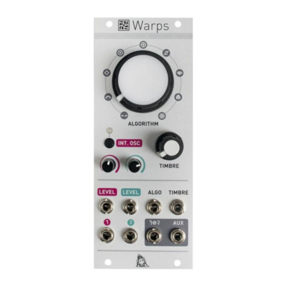
CONTROLS, INPUTS AND OUTPUTS
A. Modulation algorithm. This knob selects which signal processing operation is performed on the carrier and modulator. The algorithms are
described in further details in the next section.
B. Modulation timbre. This knob controls the intensity of the high harmonics created by cross-modulation - or provides another dimension of
tone control for some algorithms.
C. Internal oscillator state. This button enables the internal oscillator and selects its waveform. The color of the LED depends on the oscillator
waveform - when the LED is off, the internal oscillator is disabled and an external signal is used as a carrier.
D. External carrier amplitude or internal oscillator frequency. When an external carrier is used (that is to say, when the internal oscillator is
switched off), this knob controls the amplitude of the carrier, or the amount of amplitude modulation from the channel 1 LEVEL CV input. When
the internal oscillator is active, this knob controls its frequency.
E. Modulator amplitude. This knob controls the amplitude of the modulator, or the amount of amplitude modulation from the channel 2 LEVEL
CV input. Note that gains above 1.0 can be applied, for a warm overdrive effect!
1. External carrier amplitude or internal oscillator frequency CV input. When the internal oscillator is switched off, this CV input controls the
gain of the carrier input. When the internal oscillator is enabled, it acts instead as a V/Oct control for the oscillator frequency.
2. Modulator amplitude CV input. This CV input controls the gain of the modulator input. Just like its carrier counterpart, it is internally
normalized to a constant +5V source when no patch cable is plugged in. When a signal is patched into this input, the amount of CV modulation
is controlled by the Modulator amplitude knob (E).
3. Algorithm CV input. The CV on this input is added to the position of the Modulation algorithm knob (A).
4. Timbre CV input. The CV on this input is added to the position of the Modulation timbre knob (B).
5. 6. Carrier (1) and modulator (2) audio inputs. Warps expects modular-level signals (typically 10Vpp, up to 20Vpp).
7. Modulator output (1x2). This is the main audio output.
8. Auxiliary output. This output carries, when the internal oscillator is disabled, the sum of the carrier and the modulator, post VCA. Otherwise,
it carries the raw waveform from the internal oscillator.
MODULATION ALGORITHMS
Advertisement
Table of Contents

Related Manuals for Mutable Instruments Warps


Summary of Contents for Mutable Instruments Warps
- Page 1 INSTALLATION Warps is designed for Eurorack synthesizer systems and occupies 10 HP of space. It requires a -12V / +12V supply (2x5 connector), consuming 5mA from the -12V rail and 110mA from the +12V rail. The red stripe of the ribbon cable must be oriented on the same side as the “Red stripe”...
- Page 2 Vocoder. A classic implementation of an analog vocoder, with a bank of 20 analysis and 20 synthesis third-octave 48dB filters. The modulator sub-band signals are processed by envelope followers from which are derived the gains of each of the carrier sub-band signals. TIMBRE warps the connections between the modulator’s envelope followers and the carrier’s gain elements - effectively shifting up or down the formants...
- Page 3 WARRANTY This product is covered by Mutable Instruments’ warranty, for one year following the date of manufacture. This warranty covers any defect in the manufacturing of this product. This warranty does not cover any damage or malfunction caused by incorrect use - such as, but not limited to, power cables connected backwards, excessive voltage levels, or exposure to extreme temperature or moisture levels.
Need help?
Do you have a question about the Warps and is the answer not in the manual?
Questions and answers