Ozone Solutions Waterzone Series Installation & Operation Manual
Ozone injection system
Hide thumbs
Also See for Waterzone Series:
- Installation & operation manual (20 pages) ,
- Installation & operation manual (20 pages)

Related Manuals for Ozone Solutions Waterzone Series


Summary of Contents for Ozone Solutions Waterzone Series
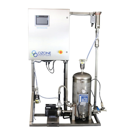
- Page 1 Waterzone Series Ozone Injection System Model: Water zone 20 Installation & Operations Manual 451 Black Forest Road, Hull, Iowa, 51239 | 712.439.6880 | info@ozonesolutions.com www.ozonesolutions.com...
-
Page 3: Table Of Contents
Table of Contents SECTION 1 SECTION 4 HMI Control Display - Overview ......12 Safety Precautions ......... 4 HMI Control Display - Root Screen ....13 Introduction ........... 4 Theory of Operation ........4 SECTION 5 Warranty .............. 14 SECTION 2 Contact Information .......... -
Page 4: Safety Precautions
Unauthorized entry can result in serious injury erator at pressures up to 15 PSI. or death. For service instructions, contact Ozone Solutions. The process of converting oxygen into ozone is an 5. Make sure all tubing connections between the energy intensive process that generates a large Ozone Generator and the injection point are amount of heat. - Page 5 The process of converting oxygen into ozone is an Naturally, the excess oxygen and a small amount of energy intensive process that generates a large undissolved ozone must be removed from the water; amount of heat. This heat must be removed from the this occurs in the contact tank located on the skid.
-
Page 6: Component Diagram
SECTION 2 Component Diagram... -
Page 7: Components Description
Components Description 7. Water Trap: These units prevent water from flowing with the gas stream to the ozone de- 1. Ozone Destruct Unit: Safely converts off- struct unit, and potentially the ozone generator gassed ozone into oxygen using a catalyst ma- (in a reverse flow situation). -
Page 8: Specifications
Ventilation: The system should be installed in a well- guidelines for certain system configurations, contact ventilated area, in accordance with the environmental Ozone Solutions if the environmental conditions are not specifications outlined in the individual Operation s prescribed above, or otherwise in question. - Page 9 O3 GENERATOR COOLING WATER IN: is the 1/4 Some Waterzone systems are configured with an inch brass female NPT fitting on the side of the control- Ozone Destruct Unit installed on the skid. If pre- ler near the cooling water flow meter. This must be sent, the gas exiting this ozone destruct unit connected to a consistent water supply of cool fresh should still be plumbed to a safe location in the...
-
Page 10: Operation Guidelines
Section 3 System Control Read the “Ozone System Controls and Indicators” System Operation to become familiar with the individual compo- nents before attempting to operate the system. The IMPORTANT: Read and understand the “Caution, system can be operated from a remote location if Warnings and Hazards”... -
Page 11: Operator Startup
Ozone System Initial Startup 7. Ensure that air bubbles are escaping from the air vent; this will indicate the oxygen is being Procedure introduced into the water and off-gassed effec- tively. Normally, a small amount of water will IMPORTANT: Read and understand the “Caution, periodically exit the air vent along with the Warnings and Hazards”... -
Page 12: Hmi Control Display - Overview
Section 4 HMI Control Display - Overview The HMI panel allows access to all automatic functions of this Ozone Injection System. All of the system compo- nents operate automatically, while the HMI panel displays the current status of each part of the system. Various set points (to adjust running parameters and alarm parameters) can be adjusted by the operator during shutdown or dur- ing operation. -
Page 13: Hmi Control Display - Root Screen
HMI Control Display Continued... -
Page 14: Warranty
For to by Ozone Solutions or by an authorized dealer. such products, the manufacturer warranty will super- sede this warranty. Ozone Solutions will honor the Ozone Solutions reserves the right to make changes manufacturer’s warranty, but if and when advised by... -
Page 15: Troubleshooting
Troubleshooting Symptom Possible Cause Repair System does not run Alarm Condition - Message in alarm log Resolve alarm condition No Power Check and repair incoming power External stop contacts Ensure external contacts are open Flow less than 5 gpm flow switch not ac- Increase water flow tive Low dissolved ozone levels Water is contaminated... -
Page 16: Appendix A - Cad Drawing
Section 6 Appendix A - CAD Drawing... -
Page 17: Appendix B - Maintenance
Appendix B - Maintenance All major components requiring maintenance have guidelines listed in the respective operation manuals. Refer to those individual operation manuals for other preventative maintenance and regular maintenance information. Maintenance Table Component Action Tim Interval Part Number(s) Compressed Air Filter Replace filter element 3 months/as needed PR-8: Replacement filter... -
Page 18: Appendix B - Msds
Appendix C - OSHA... - Page 20 451 Black Forest Road, Hull, Iowa, 51239 | 712.439.6880 | info@ozonesolutions.com www.ozonesolutions.com ©2016, Ozone Solutions. All Rights reserved. Ozone Solutions is a r egister ed tr ademar k. This publication may not be reproduced in part or whole without written permission of Ozone Solutions...
Need help?
Do you have a question about the Waterzone Series and is the answer not in the manual?
Questions and answers