Ozone Solutions Waterzone Series Installation & Operation Manual
Ozone injection system
Hide thumbs
Also See for Waterzone Series:
- Installation & operation manual (20 pages) ,
- Installation & operation manual (20 pages)

Related Manuals for Ozone Solutions Waterzone Series


Summary of Contents for Ozone Solutions Waterzone Series
- Page 1 Waterzone Series Ozone Injection System Model: Water zone 100 Installation & Operations Manual 451 Black Forest Road, Hull, Iowa, 51239 | 712.439.6880 | info@ozonesolutions.com www.ozonesolutions.com...
-
Page 3: Table Of Contents
Table of Contents SECTION 1 SECTION 4 Safety Precautions ......... 4 HMI Control Display - Overview ....12 Introduction ........... 4 HMI Control Display - Root Screen ....13 Theory of Operation ........4 SECTION 5 SECTION 2 Personal Safety ..........13 Component Diagram ........6 Warranty ............14 Component Description ......... -
Page 4: Safety Precautions
For service instructions, contact amount of heat. This heat must be removed from Ozone Solutions. the ozone generating cell for efficient and reliable operation. The ozone generator in this system uses 5. - Page 5 This ozone/oxygen mix is dissolved into the water Naturally, the excess oxygen and a small amount of using the Ozone Injection System. To efficiently dis- undissolved ozone must be removed from the water; solve this ozone into the water, a Venturi Injector is this occurs in the contact tank located on the skid.
-
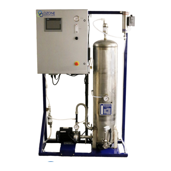
Page 6: Component Diagram
SECTION 2 Component Diagram... -
Page 7: Component Description
Components Description 9. Venturi Injector: A Venturi Injector is used to pull the ozone into the water using a vacuum 1. Ozone Destruct Unit (option): Safely converts and mix this ozone gas into water very effi- off-gassed ozone into oxygen using a catalyst ciently. -
Page 8: Specifications
Ventilation: The system should be installed in a well- Ozone Solutions if the environmental conditions are not ventilated area, in accordance with the environmental as prescribed above, or otherwise in question. - Page 9 O3 GENERATOR COOLING WATER IN: is the 1/4 Some Waterzone systems are configured with an inch brass female NPT fitting on the side of the controller Ozone Destruct Unit installed on the skid. If pre- near the cooling water flow meter. This must be connect- sent, the gas exiting this ozone destruct unit ed to a consistent water supply of cool fresh water.
-
Page 10: Operation Guidelines
Section 3 System Control Read the “Ozone System Controls and Indicators” System Operation to become familiar with the individual compo- nents before attempting to operate the system. The IMPORTANT: Read and understand the “Caution, system can be operated from a remote location if Warnings and Hazards”... -
Page 11: Operator Startup
Ozone System Initial Startup 7. Ensure that air bubbles are escaping from the air vent; this will indicate the oxygen is being Procedure introduced into the water and off-gassed effec- tively. Normally, a small amount of water will IMPORTANT: Read and understand the “Caution, periodically exit the air vent along with the Warnings and Hazards”... -
Page 12: Hmi Control Display - Overview
Section 4 HMI Control Display - Overview... -
Page 13: Hmi Control Display - Root Screen
HMI Control Display - Root Screen Whenever possible it is recommended that the machine run with maximum permissible air and oxygen flow for at least 10 minutes with the Ozone Generator OFF in order to flush out most residual ozone. If the machine cannot be operated prior to maintenance or repair, a waiting period of 12 to 24 hours (if ozone has been produced recently) is recommended to allow... -
Page 14: Warranty
Ozone Solutions or by an authorized dealer. ly with the manufacturer. Ozone Solutions reserves the right to make changes This warranty covers all parts that are not outlined in in its products without notice. -
Page 15: Appendix A - Cad Drawing
Appendix A - CAD Drawing *Waterzone -10 Specification... -
Page 16: Appendix B - Maintenance
Appendix B - Maintenance All major components requiring maintenance have guidelines listed in the respective operation manuals. Refer to those individual operation manuals for other preventative maintenance and regular maintenance information. Maintenance Table Component Action Tim Interval Part Number(s) Compressed Air Filter Replace filter element 3 months/as needed PR-8: Replacement filter... -
Page 17: Appendix C - Troubleshooting
Appendix C - Troubleshooting Symptom Possible Cause Repair System does not run Alarm Condition - Message in alarm log Resolve alarm condition No Power Check and repair incoming power External stop contacts Ensure external contacts are open Flow less than 5 gpm flow switch not ac- Increase water flow tive Low dissolved ozone levels Water is contaminated... -
Page 18: Appendix D - Msds
Appendix D - OSHA... - Page 20 451 Black Forest Road, Hull, Iowa, 51239 | 712.439.6880 | info@ozonesolutions.com www.ozonesolutions.com ©2016, Ozone Solutions. All Rights reserved. Ozone Solutions is a r egister ed tr ademar k. This publication may not be reproduced in part or whole without written permission of Ozone Solutions...
Need help?
Do you have a question about the Waterzone Series and is the answer not in the manual?
Questions and answers