Table of Contents
Advertisement
Quick Links
Advertisement
Table of Contents

Related Manuals for Neousys Nuvo-6108GC Series

Summary of Contents for Neousys Nuvo-6108GC Series
- Page 1 Neousys Technology Inc. Nuvo-6108GC Series User Manual Revision 1.3...
-
Page 2: Table Of Contents
Table of Contents Table of Contents Table of Contents ........................2 Legal Information ........................4 Contact Information ....................... 5 Declaration of Conformity ..................... 5 Copyright Notice ........................6 Safety Precautions......................... 7 Hot Surface Warning......................7 Battery Warning........................ - Page 3 Table of Contents 3.2.5 Installing HDD/ SSD to SATA Port 1 ..............63 3.2.6 Installing HDD/ SSD to SATA Ports 2/ 3/ 4 ............65 3.2.7 Installing External 2.5” HDD/ SSD (Nuvo-6108GC-IGN Only) ......67 3.2.8 PCI/ PCIe Add-on Card Installation ..............69 Installing the System Enclosure ................
-
Page 4: Legal Information
For questions in regards to hardware/ software compatibility, customers should contact Neousys Technology Inc. sales representative or technical support. To the extent permitted by applicable laws, Neousys Technology Inc. shall NOT be responsible for any interoperability or compatibility issues that may arise when (1) products, software, or options not certified and supported;... -
Page 5: Contact Information
Neousys Technology Inc. (Taipei, Taiwan) 15F, No.868-3, Zhongzheng Rd., Zhonghe Dist., New Taipei City, 23586, Taiwan Tel: +886-2-2223-6182 Fax: +886-2-2223-6183 Email, Website Americas Neousys Technology America Inc. 3384 Commercial Avenue, Northbrook, IL 60062, USA (Illinois, USA) Tel: +1-847-656-3298 Email, Website China Neousys Technology (China) Ltd. -
Page 6: Copyright Notice
Disclaimer This manual is intended to be used as an informative guide only and is subject to change without prior notice. It does not represent commitment from Neousys Technology Inc. Neousys Technology Inc. shall not be liable for any direct, indirect, special, incidental, or consequential damages arising from the use of the product or documentation, nor for any infringement on third party rights. -
Page 7: Safety Precautions
24Vdc, 16A, Tma 60 degree C and 5000m altitude during operation. If further assistance is required, please contact Neousys Technology If the system is not going to be used for a long time, disconnect it from mains... -
Page 8: Service And Maintenance
Table of Contents Service and Maintenance ONLY qualified personnel should service the system Shutdown the system, disconnect the power cord and all other connections before servicing the system When replacing/ installing additional components (expansion card, memory module, etc.), insert them as gently as possible while assuring proper connector engagement ESD Precautions ... -
Page 9: About This Manual
About This Manual About This Manual This guide introduces Neousys Nuvo-6108GC series system. An industrial grade GPU computer integrating high-end NVIDIA® graphics card with Intel® Xeon® E3 v5 or 6 Gen Core™ processors. The guide also demonstrates the system’s basic installation procedures. -
Page 10: Introduction
Nuvo-6108GC/ Nuvo-6108GC-IGN Introduction The Neousys Nuvo-6108GC is the world’s first industrial-grade GPU computer integrating NVIDIA® graphics card and an Intel Xeon processor. The perfect replacement for 19” rackmount IPC systems, Nuvo-6108GC is powered by Intel® Xeon® E3 v5 or 6 Gen Core™... -
Page 11: Nuvo-6108Gc Specifications
Nuvo-6108GC/ Nuvo-6108GC-IGN Nuvo-6108GC Specifications System Core Supports Intel® Xeon® E5 v3 and 6th-Gen Core™ LGA1151 CPU - Intel® Xeon® Processor E3-1275 v5 (8M Cache, 3.6/4.0 GHz)* - Intel® Xeon® Processor E3-1268L v5 (8M Cache, 2.4/3.4 GHz) - Intel® Core™ i7-6700 (8M Cache, 3.4/4.0 GHz)* Processor - Intel®... - Page 12 Nuvo-6108GC/ Nuvo-6108GC-IGN With E3-1268L v5: 50.16W@24VDC Max. Power With i7-6700TE (35W TDP): 53.76W@24VDC Consumption With i5-6500TE (35W TDP): 35.04W@24VDC With i3-6500TE (Max. TDP): 58.08W@24VDC Mechanical Dimension 164 mm (W) x 360 mm (D) x 174 mm (H) Weight Approx. 4.7 kg (including CPU, memory, HDD) Mounting Damping bracket (Standard) Environmental...
-
Page 13: Nuvo-6108Gc-Ign Specification
Nuvo-6108GC/ Nuvo-6108GC-IGN Nuvo-6108GC-IGN Specification System Core Supports Intel® Xeon® E5 v3 and 6th-Gen Core™ LGA1151 CPU - Intel® Xeon® Processor E3-1275 v5 (8M Cache, 3.6/4.0 GHz)* - Intel® Xeon® Processor E3-1268L v5 (8M Cache, 2.4/3.4 GHz) - Intel® Core™ i7-6700 (8M Cache, 3.4/4.0 GHz)* Processor - Intel®... - Page 14 Nuvo-6108GC/ Nuvo-6108GC-IGN With E3-1268L v5: 50.16W@24VDC Max. Power With i7-6700TE (35W TDP): 53.76W@24VDC Consumption With i5-6500TE (35W TDP): 35.04W@24VDC With i3-6500TE (Max. TDP): 58.08W@24VDC Mechanical Dimension 164 mm (W) x 360 mm (D) x 174 mm (H) Weight Approx. 4.7 kg (including CPU, memory, HDD) Mounting Damping bracket (Standard) Environmental...
-
Page 15: Dimension
Nuvo-6108GC/ Nuvo-6108GC-IGN Dimension NOTE All measurements are in millimeters (mm). 1.3.1 I/O Panel View Nuvo-6108GC Nuvo-6108GC-IGN... -
Page 16: Removable Side Panel View
Nuvo-6108GC/ Nuvo-6108GC-IGN 1.3.2 Removable Side Panel View Nuvo-6108GC Nuvo-6108GC-IGN... -
Page 17: I/O Panel View With Damping Bracket Installed
Nuvo-6108GC/ Nuvo-6108GC-IGN 1.3.3 I/O Panel View with Damping Bracket Installed Nuvo-6108GC Nuvo-6108GC-IGN... -
Page 18: Bottom View With Damping Bracket Installed
Nuvo-6108GC/ Nuvo-6108GC-IGN 1.3.4 Bottom View with Damping Bracket Installed Nuvo-6108GC Nuvo-6108GC-IGN... -
Page 19: System Overview
Upon receiving and unpacking your Nuvo-6108GC, please check immediately if the package contains all the items listed in the following table. If any item(s) are missing or damaged, please contact your local dealer or Neousys Technology. Nuvo-6108GC Packing List System... -
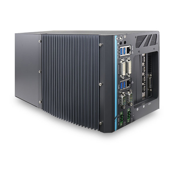
Page 20: External I/O
Nuvo-6108GC/ Nuvo-6108GC-IGN External I/O The Nuvo-6108GC series I/O panel features dual gigabit Ethernet, four USB3.0, dual DVI ports (off motherboard chipset), dual serial ports, 3-pin ignition and DC input (Nuvo-6108GC-IGN only), 3-pin terminal and 3-pin on/ off control. Nuvo-6108GC Nuvo-6108GC-IGN... - Page 21 Nuvo-6108GC/ Nuvo-6108GC-IGN adapter. USB 3.0 port supports up to 5 Gbit/s data transfer USB 3.0 port bandwidth. Implemented via Intel I210-LM, the Gigabit Ethernet port GbE port offers fast network access. software-selectable RS-232/422/485 ports. COM port operation mode of COM1 and COM2 can be set in BIOS. 3-pin terminal block The system accepts 24V DC power input.
-
Page 22: Reset Button
Nuvo-6108GC/ Nuvo-6108GC-IGN 2.3.1 Reset Button The reset button is used to manually reset the system in case of system halt or malfunction. To avoid unexpected reset, the button is purposely placed behind the panel. To reset, please use a pin-like object (eg. tip of a pen) to access the reset button. -
Page 23: Power Button
The power button is a non-latched switch for ATX mode on/off operation. To turn on the Nuvo-6108GC series, press the power button and the PWR LED should light-up green. To turn off Nuvo-6108GC, issuing a shutdown command in OS is preferred, or you can simply press the power button. -
Page 24: 4-Pole 3.5Mm Speaker-Out/ Microphone-In Jack
Nuvo-6108GC/ Nuvo-6108GC-IGN 2.3.3 4-pole 3.5mm Speaker-out/ Microphone-in Jack The system’s audio output is provided via Intel® High Definition Audio (built-in in H110 PCH) and Realtek ALC262 codec. The port is used for speaker / headphone output. To utilize the audio function in Windows, you need to install corresponding drivers for both Intel®... -
Page 25: Led Indicators
Nuvo-6108GC/ Nuvo-6108GC-IGN 2.3.4 LED Indicators There are four LED indicators on the I/O panel: PWR, UID, WDT and HDD. The descriptions of these three LED are listed in the following table. Indicator Color Description Green lid when system is on. Power indictor, Green Reserved for future usage. -
Page 26: Usb 3.0 Port
Nuvo-6108GC/ Nuvo-6108GC-IGN 2.3.5 USB 3.0 Port The system’s USB 3.0 (SuperSpeed USB) ports are implemented by native xHCI (eXtensible Host Controller Interface) controller and are backward compatible with USB 2.0, USB 1.1 and USB 1.0 devices. Legacy USB is also supported so you can use USB keyboard/mouse in DOS environment xHCI driver is supported natively in Windows 10, therefore you do not need to install xHCI driver in prior to utilize USB functions. -
Page 27: Gbe Port
Nuvo-6108GC/ Nuvo-6108GC-IGN 2.3.6 GbE Port The system offers 2 GbE ports on its I/O panel. The GbE ports are marked in blue/ ® ® and are implemented with Intel I219-LM/ Intel I210-IT controllers, respectively. Each port has one dedicated PCI Express link for maximum performance. When an Ethernet connection is established, the LED indicators on the RJ45 connector represents the following connection statuses: Active/Link LED... -
Page 28: Dvi Port
The system has two DVI connectors on its I/O panel to support dual independent display outputs. DVI transmits graphics data in digital format and therefore can deliver better image quality at high resolutions. For VGA monitor, Neousys offers a specialized DVI-to-VGA adapter as an accessory shipped with the system. This adapter supports VGA DDC signals and thus eliminates compatibility issues with VGA monitors. -
Page 29: Com Port
Nuvo-6108GC/ Nuvo-6108GC-IGN 2.3.8 COM Port The system provides totally five COM ports for communicating with external devices. These COM ports are implemented using industrial-grade ITE8786 Super IO chip (-40 to 85°C) and provide up to 115200 bps baud rate. COM1 and COM2 are software-selectable RS-232/422/485 ports. The operation mode of COM1 and COM2 can be set in BIOS setup utility. - Page 30 Nuvo-6108GC/ Nuvo-6108GC-IGN COM Port Pin Definition COM1 & COM2 RS-485 Mode Pin# RS-232 Mode RS-422 Mode (Two-wire 485) 422 TXD+ 485 TXD+/RXD+ 422 RXD+ 422 RXD- 422 TXD- 485 TXD-/RXD-...
-
Page 31: 3-Pin Terminal Block For Dc Input
Nuvo-6108GC/ Nuvo-6108GC-IGN 2.3.9 3-Pin Terminal Block for DC Input The system accepts 24V DC power input via a 3-pin pluggable terminal block, which is fit for field-use where DC power is usually provided. The screw clamping mechanism on the terminal block offers connection reliability when wiring DC power. Symbol Description Negative polarity (ground) of DC input... -
Page 32: 2.3.10 3-Pin Remote On/ Off
Nuvo-6108GC/ Nuvo-6108GC-IGN 2.3.10 3-Pin Remote On/ Off The “Remote On/ Off” 3-pin connection allows for external switch extension. It is useful when the system is placed in a cabinet or a not easily accessed location. -
Page 33: 3-Pin Terminal Block (Dc/ Ignition Input)
Nuvo-6108GC/ Nuvo-6108GC-IGN 2.3.11 3-pin Terminal Block (DC/ Ignition Input) The system accepts 24VDC power input via a 3-pin pluggable terminal block, which is fit for field usage where DC power is usually provided. The screw clamping mechanism on the terminal block offers connection reliability when wiring DC power. In addition to DC power input, this terminal block can also accept ignition signal input (IGN). -
Page 34: Internal I/O Functions
Nuvo-6108GC/ Nuvo-6108GC-IGN Internal I/O Functions In addition to I/O connectors on the front panel, the system also provides internal on-board connectors, such as remote on/off control, LED status output, internal USB 2.0 ports, 12V power and etc. In this section, we’ll illustrate these internal I/O functions. - Page 35 Nuvo-6108GC/ Nuvo-6108GC-IGN Pin Definition Pin# Definition Description WDT_LED- [Output] Watchdog timer indicator, flashing when watchdog timer is started. WDT_LED+ UID_LED- [Output] User defined LED, reserved for future usage UID_LED+ HDD- [Output] Hard drive indicator, flashing when SATA hard drive is active. HDD+ Power_LED- [Output]System power indicator, on if system is turned...
-
Page 36: Dual Dram Sodimm Slot
Nuvo-6108GC/ Nuvo-6108GC-IGN 2.4.2 Dual DRAM SODIMM Slot The system motherboard supports two 260-pin SODIMM socket for installing DDR4 memory module up to 32GB. Each slot supports single module DDR4 2133MHz SODIMM up to 16GB capacity. -
Page 37: Mini-Pcie Slot And Pin Definition
Nuvo-6108GC/ Nuvo-6108GC-IGN 2.4.3 mini-PCIe Slot and Pin Definition The system has a mini-PCIe slot for installing a mini-PCIe module, you can add additional features to your system such as WIFI.. For WiFi communication, SMA antenna apertures can be located on the I/O panel, next to the speaker jack. - Page 38 Some off-the-shelf mini-PCIe 4G modules are not compliant to standard mini-PCIe interface. They use 1.8V I/O signals instead of standard 3.3V I/O and may have signal conflict. Please consult with Neousys for compatibility when in doubt! Installing an incompatible 4G module may damage the system or the module itself...
-
Page 39: B Key) And Sim Card Slot
Nuvo-6108GC/ Nuvo-6108GC-IGN 2.4.4 M.2 (B Key) and SIM Card Slot The system has a M.2 (indicated in blue) slot that works in cooperation with a SIM slot (indicated in red). By installing a M.2 module, you can install a 3G/ 4G module with a SIM card for internet access via your service provider’s 3G/ 4G network. - Page 40 Nuvo-6108GC/ Nuvo-6108GC-IGN M.2 Slot Pin Definition Pin # Signal Pin # Signal P3V3 P3V3 USB_D+ USB_D- UIM_RST UIM_CLK UIM_DATA UIM_PWR PLTRST PLTRST P3V3 P3V3 P3V3...
-
Page 41: Sata Port 1
Nuvo-6108GC/ Nuvo-6108GC-IGN 2.4.5 SATA Port 1 The system features four SATA ports. SATA port No. 1 located near the center of the motherboard via a 22-pin SATA connector. You can directly mount a 2.5” HDD/SSD to this port using the bracket that came with the system. For installing procedures, please refer to “Installing HDD/ SSD to SATA Port 1”. -
Page 42: Sata Ports 2, 3 And 4
Nuvo-6108GC/ Nuvo-6108GC-IGN 2.4.6 SATA Ports 2, 3 and 4 The system has a total of four SATA ports. In addition to SATA port No. 1 mentioned in the previous section, from left to right, SATA port No. 2, 3 and 4 are located at the bottom of the motherboard via 22-pin SATA connectors. -
Page 43: Internal Usb Port On Extension Board
Nuvo-6108GC/ Nuvo-6108GC-IGN 2.4.7 Internal USB Port on Extension Board The system’s daughter board has an internal USB2.0 port on the PCBA. You can utilize this USB port to connect a USB protection dongle inside the chassis of the system. -
Page 44: Pcie 8-Pin And 6-Pin 12V Vdc Power Connector
Nuvo-6108GC/ Nuvo-6108GC-IGN 2.4.8 PCIe 8-Pin and 6-Pin 12V VDC Power Connector For high performance graphics cards, an additional 12V input is required. The system offers an 8-pin and a 6-pin PCIe power connector on its daughter board. It supports a PCI Express graphics card with up to 250W TDP. Pin# Pin Definition 12 VDC... -
Page 45: X16/ X8 Pci Express Slots
Nuvo-6108GC/ Nuvo-6108GC-IGN 2.4.9 X16/ x8 PCI Express Slots The system has two x8 (indicated in red) and one x16 (indicated in blue) PCI Express slot. The x8 slot is running at Gen3, 4-lanes PCIe signals and can deliver up to 7.9GB/s bandwidth. The x16 slot is running at Gen3, offering 16-lanes PCIe signals and can deliver up to 15.8GB/s bandwidth. -
Page 46: System Installation
Nuvo-6108GC/ Nuvo-6108GC-IGN System Installation Before disassembling the system enclosure and installing components and modules, please make sure you have done the following: It is recommended that only qualified service personnel should install and service this product to avoid injury or damage to the system. ... -
Page 47: Disassembling The System
Nuvo-6108GC/ Nuvo-6108GC-IGN Disassembling the System To access system internal components, the system needs to be disassembled. To disassemble the system enclosure, you need to remove screws on the I/O panel, removable side panel and system ventilation panel. On the I/O panel side, unscrew the screw shown below. - Page 48 Nuvo-6108GC/ Nuvo-6108GC-IGN Unscrew the five screws on the removable side panel shown below. Unscrew the two screws on the system ventilation fan panel shown below.
- Page 49 Nuvo-6108GC/ Nuvo-6108GC-IGN Due to the clip on mechanism (indicated in blue), to remove the side panel, you need to gently slide it upwards and then pull outwards to remove the side panel. Slide upwards Pull outwards Remove the graphics card support frame by unscrewing the four screws shown and slide upwards to remove the support frame.
- Page 50 Nuvo-6108GC/ Nuvo-6108GC-IGN To remove the daughter board, unscrew the four screws shown. Gently disengage the daughter board from the motherboard and out of the enclosure.
- Page 51 Nuvo-6108GC/ Nuvo-6108GC-IGN On the side of enclosure, unscrew the six screws. 10. Gently lift the heatsink and motherboard upwards to separate it from the enclosure. 11. Remove the 2.5” hard drive bracket by unscrewing the two screws.
- Page 52 Nuvo-6108GC/ Nuvo-6108GC-IGN 12. Separate the motherboard from the heatsink by removing the nine screws shown below. Heatsink Motherboard...
-
Page 53: Installing Internal Components
Nuvo-6108GC/ Nuvo-6108GC-IGN Installing Internal Components 3.2.1 CPU Installation Procedure Between the motherboard and the heatsink, you’ll see the CPU socket protective cover, place finger tips underneath the sign “REMOVE” for leverage and gently lift the cover. WARNING With the protective cover removed, please be careful when handling the motherboard. - Page 54 Nuvo-6108GC/ Nuvo-6108GC-IGN Locate the CPU retention bracket from the accessory box. Place the retention bracket on the CPU and hold it in place. Turn the motherboard around and secure the bracket by tightening two M3 P-head screws. Hold CPU bracket firmly and turn Secure two M3 P-head screws the motherboard around...
- Page 55 Nuvo-6108GC/ Nuvo-6108GC-IGN Remove all thermal pads’ protective films on the heatsink. With the five motherboard standoffs aligned, gently lower the motherboard onto the heatsink.
- Page 56 Nuvo-6108GC/ Nuvo-6108GC-IGN Once the motherboard has been installed, you’re ready to secure the five screws that help the heatsink apply pressure to the CPU/ chipset die. You’ll want to apply even pressure to the corners by gradually tightening each screw. Reinstall the system enclosure, daughter board and panel when done.
-
Page 57: Ddr4 So-Dimm Installation
Nuvo-6108GC/ Nuvo-6108GC-IGN 3.2.2 DDR4 SO-DIMM Installation There are two memory SO-DIMM slots on the motherboard that support a total maximum of 32GB DDR4-2133. Please follow the procedures below to replace or install the memory modules. 1. Please refer to the section “Disassembling the System”, you may not need to completely dismantle the system to gain access to the memory module slots. - Page 58 Nuvo-6108GC/ Nuvo-6108GC-IGN 4. Push the memory module down until it is clipped-in. 5. Repeat steps 3 and 4 to install the other module. Reinstall the system enclosure and panel when done. 7. If you need to install other components, please refer to respective sections.
-
Page 59: Module, Sim Card And Antennae Installation
Nuvo-6108GC/ Nuvo-6108GC-IGN 3.2.3 M.2 Module, SIM Card and Antennae Installation The system has a M.2 slot (indicated in red) coupled with SIM socket (indicated in blue) for installing 3G/ 4G module. For installation, please refer to the following instructions. Please refer to the section “Disassembling the System”, you may not need to completely dismantle the system to gain access to the M.2 slot and SIM socket. - Page 60 Nuvo-6108GC/ Nuvo-6108GC-IGN Insert the M.2 module on a 45 degree angle into the M.2 slot and secure the module. Insert on 45 degree angle Secure the module Clip on the IPEZ-to-SMA cable to the module and secure the antenna to the rear panel.
-
Page 61: Mini-Pcie Module And Antennae Installation
Nuvo-6108GC/ Nuvo-6108GC-IGN 3.2.4 mini-PCIe Module and Antennae Installation The system has a mini-PCIe slot (indicated in blue) for installing WiFi module. For installation, please refer to the following instructions. Please refer to the section “Disassembling the System”, you may not need to completely dismantle the system to gain access to the mini-PCIe slot. - Page 62 Nuvo-6108GC/ Nuvo-6108GC-IGN Gently press down and secure the module with an M2.5 P-head screw. Clip on the IPEZ-to-SMA cable to the module and secure the antenna to the rear panel. Please refer to the module’s manual for clip-on connection. Clip on IPEZ-to-SMA cable Secure antenna to rear panel Reinstall the system enclosure and panel when done.
-
Page 63: Installing Hdd/ Ssd To Sata Port 1
Nuvo-6108GC/ Nuvo-6108GC-IGN 3.2.5 Installing HDD/ SSD to SATA Port 1 The system has four SATA ports. SATA port 1 indicated in blue requires a bracket to install the HDD/ SSD. The SATA ports 2/ 3/ 4 indicated in require the HDDs/ SSDs to be installed on a tray. - Page 64 Nuvo-6108GC/ Nuvo-6108GC-IGN Reinstall the system enclosure and panel when done. If you need to install other components, please refer to respective sections.
-
Page 65: Installing Hdd/ Ssd To Sata Ports 2/ 3/ 4
Nuvo-6108GC/ Nuvo-6108GC-IGN 3.2.6 Installing HDD/ SSD to SATA Ports 2/ 3/ 4 The system has four SATA ports. SATA port 1 indicated in blue requires a bracket to install the HDD/ SSD. The SATA ports 2/ 3/ 4 indicated in require the HDDs/ SSDs to be installed on a tray. - Page 66 Nuvo-6108GC/ Nuvo-6108GC-IGN Align the HDD/ SSD to the preset screw holes (4 per drive) and secure the drives onto the tray using flathead screws. Use flathead screws to secure drive(s) Drive(s) secured on the tray Gently reinsert the tray back underneath the daughterboard while making sure the clips on both sides of the tray that holds the tray in-place.
-
Page 67: Installing External 2.5" Hdd/ Ssd (Nuvo-6108Gc-Ign Only)
Nuvo-6108GC/ Nuvo-6108GC-IGN 3.2.7 Installing External 2.5” HDD/ SSD (Nuvo-6108GC-IGN Only) The Nuvo-6108GC-IGN has two external 2.5” HDD/ SSD slots (indicated in blue). They support 9mm drives that can be accessed from the side panel. To install a HDD/ SSD, please loosen the thumb screw (indicated in red) on the 2.5”... - Page 68 Nuvo-6108GC/ Nuvo-6108GC-IGN Once the hard drive is secured onto the tray, it is ready to be inserted back into the enclosure. When inserting, please make sure the SATA is inserted first and the tray slides under the notches inside the 2.5” tray opening. Once the tray has engaged the notches, gently push the tray all the way into the enclosure and secure the tray with the thumb screw.
-
Page 69: Pci/ Pcie Add-On Card Installation
Nuvo-6108GC/ Nuvo-6108GC-IGN 3.2.8 PCI/ PCIe Add-on Card Installation The system provides two 8x PCI (indicated in blue) and one 16x PCIe (indicated in red) slots on the daughterboard. Please refer the following instructions on installing add-on cards. Please refer to the section “Disassembling the System”, you may not need to completely dismantle the system to gain access to the PCI/ PCIe slots. - Page 70 Nuvo-6108GC/ Nuvo-6108GC-IGN Install the PCIe graphics card support frame. Slide and insert the support frame Secure frame with four screws When installing a graphics card, please make sure that you do not accidently knock off the spacer on the inside of the support frame.
- Page 71 Nuvo-6108GC/ Nuvo-6108GC-IGN To install the PCI/ PCIe card, gently lower and insert the card’s gold fingers into the PCI/ PCIe slot; make sure the tab at the bottom of the bezel plate is inserted into the notch. Gently insert gold fingers into the slot Bezel tab inserted into notch Graphics card Secure the gaphics card...
- Page 72 Nuvo-6108GC/ Nuvo-6108GC-IGN Install the stabilizing bracket to hold the graphics card to the support frame. Graphics card stabilizing bracket Secure the bracket with four screws Connect the 8-pin and/ or 6-pin power supply for the card. Reinstall the system enclosure and panel when done.
-
Page 73: Installing The System Enclosure
Nuvo-6108GC/ Nuvo-6108GC-IGN Installing the System Enclosure To reinstall the system enclosure, place the side panel back onto the enclosure while making sure the two (2) notches are inserted into the slide-and-lock holes on enclosure frames. Place side panel onto enclosure Slide-and-lock... - Page 74 Nuvo-6108GC/ Nuvo-6108GC-IGN Secure screws on the I/O panel highlighted in blue. Secure the screw on top of the enclosure highlighted in blue.
- Page 75 Nuvo-6108GC/ Nuvo-6108GC-IGN Secure screws on the removable side panel highlighted in blue. Secure screws on the ventilation fan panel highlighted in blue to complete the enclosure installation process.
-
Page 76: Anti-Vibrate Grommet/ Mounting Bracket Installation
Nuvo-6108GC/ Nuvo-6108GC-IGN Anti-vibrate Grommet/ Mounting Bracket Installation There are eight anti-vibration grommets (in blue) in the accessory box and two mounting brackets. Secure the anti-vibration grommets and the mounting brackets with M4 screws (in red) supplied as shown in the illustration below. Once the brackets have been installed, you may proceed to secure the system on top of a flat horizontal surface. -
Page 77: Powering On The System
Nuvo-6108GC/ Nuvo-6108GC-IGN Powering On the System There are three methods to power on the system Pressing the power button Sending a LAN packet via Ethernet (Wake-on-LAN) Powering on via ignition control (Nuvo-6108GC-IGN only, please refer Ignition Control section) 3.5.1 Powering On Using the Power Button... -
Page 78: Powering On Using Wake-On-Lan
Nuvo-6108GC/ Nuvo-6108GC-IGN 3.5.2 Powering On Using Wake-on-LAN Wake-on-LAN (WOL) is a mechanism to wake up a computer system from a S5 (system off with standby power) state via issuing a magic packet. The system’s Wake-on-LAN compatible GbE port is shown below. NOTE Please make sure the Intel chipset and Ethernet driver has been properly installed prior to setting up WOL function. - Page 79 Nuvo-6108GC/ Nuvo-6108GC-IGN the operating system. Once booted into the Windows system, press “Windows key + E”, right-click on “Network>Properties>Change adapter settings”. Locate and double-click on the adapter Intel® I219 Gigabit Network Connection, click on Configure... Click on the Power Management tab and check the following options.
-
Page 80: Ignition Power Control (Nuvo-6180Gc-Ign Only)
Nuvo-6108GC/ Nuvo-6108GC-IGN Ignition Power Control (Nuvo-6180GC-IGN Only) The ignition power control module for mobile applications is a MCU-based implementation that monitors the ignition signal and reacts to turn on/off the system according to predefined on/off delay. Its built-in algorithm supports other features such as ultra-low power standby, battery-low protection, system hard-off, etc. -
Page 81: Additional Features Of Ignition Power Control
Nuvo-6108GC/ Nuvo-6108GC-IGN 3.6.2 Additional Features of Ignition Power Control In addition to the typical timing correlation, the ignition power control module offers additional features to provide additional reliability for mobile applications. 1. Low battery detection The ignition power control module continuously monitors the voltage of DC input when the system is operational. -
Page 82: Wiring Ignition Signal
Nuvo-6108GC/ Nuvo-6108GC-IGN 3.6.3 Wiring Ignition Signal To have ignition power control for mobile usage, you need to supply IGN signal to the system. The IGN input is located on the 4-pin pluggable terminal block (shared with DC power input). Below is the typical wiring configuration for mobile applications. Connect car Battery+ line (12V for sedan, 24V for bus/truck) to V+. -
Page 83: Configure Your Windows System
Nuvo-6108GC/ Nuvo-6108GC-IGN 3.6.4 Configure your Windows system When applying ignition power control to your system, please make sure you’ve configured your Windows system to initiate a shutdown process when pressing the power button. By default, Windows 7/ 8/ 10 goes to sleep (S3) mode when power button is pressed. -
Page 84: Operation Modes Of Ignition Power Control
Nuvo-6108GC/ Nuvo-6108GC-IGN 3.6.5 Operation Modes of Ignition Power Control The system offers 16 (0~15) operation modes with different power-on/power-off delay configurations. When rotary switch is set to mode 15 (0xF), the ignition power control is set to executed according to parameters configured in BIOS setup menu, which allows richer combination of power-on/ power-off delay and more detailed control parameters. - Page 85 Nuvo-6108GC/ Nuvo-6108GC-IGN Mode 3 ~ Mode 12 Mode 3 ~ Mode 12 have various power-on delay and power-off delay. Each mode supports a hard-off timeout of 10 minutes. Mode Power-on Delay Power-off Delay Hard-off Timeout 10 seconds 10 seconds 10 minutes 10 seconds 1 minute...
- Page 86 Nuvo-6108GC/ Nuvo-6108GC-IGN [BIOS POST Check] This option secures a boot-to-OS operation. If the system is failed to boot to OS (e.g. disk failure or no bootable device) Enabled within 60 seconds, ignition control module will cut off system power and retry another power on cycle. Disabled BIOS POST check is skipped.
-
Page 87: System Configuration
NOTE Not all BIOS settings will be discussed in this section. If a particular setting/ function you are after requires specific BIOS settings but is not discussed in this section, please contact Neousys Technical Support staff. -
Page 88: Com1 & Com2 Configuration
Nuvo-6108GC/ Nuvo-6108GC-IGN 4.1.1 COM1 & COM2 Configuration The system’s COM1/ COM2 ports support RS-232 (full-duplex), RS-422 (full-duplex) and RS-485 (half-duplex) mode. You can set the COM1 operating mode via BIOS settings. Another option in BIOS called “Slew Rate” defines how sharp the rising/falling edge is for the output signal of COM1. -
Page 89: Sata Configuration
Nuvo-6108GC/ Nuvo-6108GC-IGN 4.1.2 SATA Configuration The SATA controller of your system supports two (2) operating modes: AHCI and RAID mode. The AHCI mode, which exposes SATA's advanced capabilities such as hot swapping and native command queuing, is supported in several later version of operating systems. - Page 90 Nuvo-6108GC/ Nuvo-6108GC-IGN 3. Highlight the SATA port you wish to set and press Enter to bring up setting options. Scroll to and highlight the setting you wish to set and press Enter. 4. Repeat step 3 to set other SATA ports. 5.
-
Page 91: Tpm Availability
Nuvo-6108GC/ Nuvo-6108GC-IGN 4.1.3 TPM Availability Trusted Platform Module (TPM) is a hardware-based cryptoprocessor to secure hardware by integrating cryptographic keys into devices. The system is designed with on-board TPM 2.0 module. As TPM 2.0 requires 64-bit Windows 7/ 8/ 10 with UEFI boot mode, it is disable in BIOS by default. -
Page 92: Auto Wake On S5
Nuvo-6108GC/ Nuvo-6108GC-IGN 4.1.4 Auto Wake on S5 When the system is set to operate in S5 state, the user can specify a time to turn on the system, daily or monthly. Value Option Description Auto Wake on S5 Disabled The system does not turn on when operating in state S5. -
Page 93: Power On After Power Failure Option
Nuvo-6108GC/ Nuvo-6108GC-IGN 4.1.5 Power On After Power Failure Option This option defines the behavior of System series when DC power is supplied. Value Description S0 – Power On System is powered on when DC power is supplied. S5 – Power Off System is kept in off state when DC power is supplied. -
Page 94: Power & Performance (Cpu Sku Power Configuration)
Nuvo-6108GC/ Nuvo-6108GC-IGN 4.1.6 Power & Performance (CPU SKU Power Configuration) The system supports various 6 -Gen Skylake LGA1151 CPUs. A unique feature, “SKU Power Config” is implemented in BIOS to allow users to specify user-defined SKU power limit. Although the system is designed to have best thermal performance with CPUs of 35W TDP, you can install a 65W CPU and limit its SKU power (to35W) to obtain more computing power. -
Page 95: Wake On Lan Option
Nuvo-6108GC/ Nuvo-6108GC-IGN 4.1.7 Wake on LAN Option Wake-on-LAN (WOL) is a mechanism which allows you to turn on your System series via Ethernet connection. To utilize Wake-on-LAN function, you have to enable this option first in BIOS settings. Please refer “Powering On Using Wake-on-LAN”... -
Page 96: Boot Menu
Nuvo-6108GC/ Nuvo-6108GC-IGN 4.1.8 Boot Menu The Boot menu in BIOS allows you to specify the system’s boot characteristics by setting bootable device components (boot media) and method. Or, you may press F12 upon system start up and select a device you wish boot from. Value Option Description... - Page 97 Nuvo-6108GC/ Nuvo-6108GC-IGN PXE Boot Disabled Only UEFI Network Stack is supported: Preboot capability eXecution Environment (PXE) is not supported Enabled By enabling the PXE boot, one can choose to boot via I219 Only/ I210 Only or All NICs. Add Boot Options First Newly detected boot media are placed at the top of the boot order.
-
Page 98: Boot Type (Legacy/ Uefi)
Nuvo-6108GC/ Nuvo-6108GC-IGN 4.1.9 Boot Type (Legacy/ UEFI) The system supports both Legacy and Unified Extensible Firmware Interface (UEFI) boot modes. UEFI is a specification proposed by Intel to define a software interface between operating system and platform firmware. Most modern operating systems, such as Windows 7/8/10 and Linux support both Legacy and UEFI boot modes. - Page 99 Nuvo-6108GC/ Nuvo-6108GC-IGN Highlight your selection and press Enter. Press F10 to “Exit Saving Changes”.
-
Page 100: 4.1.10 Position New Boot Device
Nuvo-6108GC/ Nuvo-6108GC-IGN 4.1.10 Position New Boot Device The “Add Boot Options” allow you to determine whether a newly added device (eg. USB flash disk) is to boot as the first device to boot or the last in the boot sequence. To set the newly-installed boot device as the first or last boot device: Press F2 when the system boots up to enter the BIOS setup utility. -
Page 101: 4.1.11 Watchdog Timer For Booting
Nuvo-6108GC/ Nuvo-6108GC-IGN 4.1.11 Watchdog Timer for Booting The watchdog timer secures the boot process by means of a timer. Once the timer expires, a reset command is issued to initiate another booting process. There are two options in BIOS menu, “Automatically after POST” and “Manually after Entering OS”. -
Page 102: Legacy/ Uefi Boot Device
Nuvo-6108GC/ Nuvo-6108GC-IGN 4.1.12 Legacy/ UEFI Boot Device When you wish to set a designated boot device, you may set it as the first device to boot in Legacy or UEFI Boot Device setting. Or if you wish to manually select a boot device, you may do so by pressing F12 when the system boots up. -
Page 103: Amt Configuration
Nuvo-6108GC/ Nuvo-6108GC-IGN AMT Configuration Intel® AMT (Active Management Technology) is a hardware-based technology for remotely managing target PCs via Ethernet connection. The system supports AMT function via its Ethernet port implemented with Intel I219-LM. In prior to use AMT to remotely control the system, you need to configure AMT password and network settings. - Page 104 Nuvo-6108GC/ Nuvo-6108GC-IGN When the system boots up, press F10 to enter the MEBx configuration menu. Highlight MEBx Login and press Enter, a prompt will appear asking for password. The default password is “admin”. For further MEBx configuration details, please refer to Intel®...
-
Page 105: Raid Configuration
Nuvo-6108GC/ Nuvo-6108GC-IGN RAID Configuration The system supports RAID 0/ 1/ 5/ 10 options. To utilize the RAID function, the minimum HDDs/ SSDs must be installed for the following RAID configurations: RAID 0/ 1: Two HDDs/ SSDs RAID 5: At least three HDDs/ SSDs RAID 10: At least four HDDs/ SSDs NOTE... - Page 106 Nuvo-6108GC/ Nuvo-6108GC-IGN 5. Upon reboot, press “Ctrl + I” to enter the RAID configuration utility Please refer to the on screen RAID MENU options and instructions for configuration.
-
Page 107: Os Support And Driver Installation
RAID. For optimum operation, it is the users’ responsibility to manually check for new drivers and upgrades! Neousys may remove or update operating system compatibility without prior notice. Please contact us if your operating system of choice is not on the list. -
Page 108: Driver Installation
Nuvo-6108GC/ Nuvo-6108GC-IGN Driver Installation The system comes with a “Drivers & Utilities” DVD that offers “one-click” driver installation process. It automatically detects your Windows operating system and installs all necessary drivers for you system with a single click. 5.2.1 Install Drivers Automatically To install drivers automatically, please refer to the following procedures. -
Page 109: Install Drivers Manually
Nuvo-6108GC/ Nuvo-6108GC-IGN 5.2.2 Install Drivers Manually You can also manually install each driver for the system. Please note when installing drivers manually, you need to install the drivers in the following sequence mentioned below. Windows 10 (x64) The recommended driver installation sequence is Chipset driver (x:\Driver_Pool\Chipset_10_APL\Win_ALL\SetupChipset.exe) Graphics driver (x:\Driver_Pool\Graphics_SKL_APL\Win_7_8_10_APL_64\Setup.exe) -
Page 110: Driver Installation For Watchdog Timer Control
Nuvo-6108GC/ Nuvo-6108GC-IGN Driver Installation for Watchdog Timer Control Neousys provides a driver package which contain function APIs for Watchdog Timer control function. You should install the driver package (WDT_DIO_Setup.exe) in prior to use these functions. Please note that you must install WDT_DIO_Setup_v2.2.6 or later versions. -
Page 111: Appendix A Using Wdt & Dio
WDT and keeping resetting the timer to make sure the system or program is running. Otherwise, the system will reset. In this section, we’ll illustrate how to use the function library provided by Neousys to program the WDT functions. Currently, WDT driver library supports Windows 10 x64 and WOW64 platform. -
Page 112: Wdt And Dio Library Installation
1. Execute WDT_DIO_Setup.2.2.6.exe. and the following dialog appears. 2. Click “Next >” and specify the directory of installing related files. The default directory is C:\Neousys\WDT_DIO. 3. Once the installation has finished, a dialog will appear to prompt you to reboot the... - Page 113 Nuvo-6108GC/ Nuvo-6108GC-IGN 4. When programming your WDT or DIO program, the related files are located in Header File: \Include Library File: \Lib Function \Manual Reference: Sample Code: \Sample\WDT_Demo (Demo for Watchdog Timer)
-
Page 114: Wdt Functions
Nuvo-6108GC/ Nuvo-6108GC-IGN WDT Functions InitWDT Syntax BOOL InitWDT(void); Description: Initialize the WDT function. You should always invoke InitWDT() before set or start watchdog timer. Parameter None Return Value TRUE: Successfully initialized FALSE: Failed to initialize BOOL bRet = InitWDT() Usage SetWDT Syntax BOOL SetWDT(WORD tick, BYTE unit);... -
Page 115: Startwdt
Nuvo-6108GC/ Nuvo-6108GC-IGN StartWDT Syntax BOOL StartWDT(void); Starts WDT countdown. Once started, the WDT LED indicator Description will begin blinking. If ResetWDT() or StopWDT is not invoked before WDT countdowns to 0, the WDT expires and the system resets. Parameter None Return Value f the timeout value is given in correct format (WDT started), this function returns TRUE, otherwise FALSE...
Need help?
Do you have a question about the Nuvo-6108GC Series and is the answer not in the manual?
Questions and answers