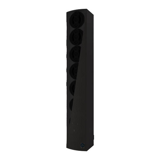
Summary of Contents for Renkus-Heinz ICONYX IC8-RN
- Page 1 Digitally Steerable Line Array Loudspeaker Systems ICONYX Gen 5 USERS MANUAL Assembly & Installation Instructions IC8-RN • IC8-RD IC16-8-RN • IC16-8-RD IC16-RN • IC16-RD IC24-16-RN • IC24-16-RD IC24-RN • IC24-RD IC32-24-RN • IC32-24-RD IC32-RN • IC32-RD...
- Page 2 IMPORTANT SAFETY INSTRUCTIONS Read these instructions. Disconnect this apparatus during lightning storms or when unused for long periods of time. Keep these instructions. Refer all servicing to qualified service personnel. Servicing is required Heed all warnings. when the apparatus has been damaged in any way, such as power-supply cord or plug is damaged, liquid has been spilled or objects have fallen Follow all instructions.
-
Page 3: Table Of Contents
TABLE OF CONTENTS PAGE INTRODUCTION ASSEMBLY INSTRUCTIONS INSTALLATION HARDWARE CONNECTIONS & INDICATORS FERRITE CLAMP INSTALLATION NETWORK CONNECTIONS DANTE NETWORKING FAULT RELAY/FAULT LED SERVICING AND TROUBLESHOOTING... -
Page 4: Introduction
Technical Support If you have any questions about Renkus-Heinz loudspeakers or encounter a problem designing, installing, setting up or operating a Renkus-Heinz system, please call our technical support staff at +1 949-588-9997 and ask the operator for technical support. Hours of operation are Monday through Friday from 8:00 AM to 5:00 PM US Pacific Time. -
Page 5: Assembly Instructions
You will need to connect a computer only when you want to change the settings or when you want to view the status of connected loudspeakers. Renkus-Heinz engineering has programmed the on board DSP to optimize the loudspeaker’s performance and to ensure its safe operation. - Page 6 Users Manual Prepare an assembly area. Modules are 3 or 6 ft. (1 or 2 meter) long, so a flat surface with enough space to assemble the complete array is required. Cover the assembly area with a heavy cloth or some other soft material to prevent damaging the finish on the cabinets while assembling them.
- Page 7 Users Manual Address Number Verification Next verify that the Aux modules are properly identified. The settings were set at the factory, but it’s always a good idea to check them. This is accomplished with the DIP switches located on the rear of each Aux module. Set the switches in accordance with the illustrations shown below. Normally the Master module (ID 0 in RHAON II) is assembled at the bottom of an array and the other modules will be Aux IDs 1, 2 &...
-
Page 8: Installation
Users Manual INSTALLATION General Information Iconyx Gen 5 was designed to be easy to install on either a flat surface, such as a wall, or suspended from a ceiling. For installation in a recess or wall or in an alcove, see our application note on flush mounting. The amplifiers are convection cooled and their heat sinks require at least an inch (25 mm) of separation from the nearest surface. - Page 9 Installation should only be performed by skilled and qualified personnel who are experienced in mounting heavy loads to the intended wall construction type. These loudspeakers are designed to be securely mounted using the included Renkus-Heinz HK series hinge kits and are not intended to be free- standing: Models: IC8-RN, IC16-8-RN &...
- Page 10 Users Manual Wall Mounting Procedure Each HK series hinge consists of two parts, a male mounting plate and a female mounting plate. The female hinge plates should be attached to the loudspeakers. The male mounting plates attach to the wall. The proper number of mounting plates are included for the size of loudspeaker ordered.
-
Page 11: Hardware Connections & Indicators
Users Manual Hardware Connections & Indicators AES/EBU Input Fault Relay Pins NC, W and NO See Fault Relay on page 14 for details Ethernet Connection RJ45 female: Yellow LED flashes when the connector is active, glows steadily when data is streaming. Green LEDs Analog Inputs 2 and 1 glow when connected but inactive, turn Orange to indicate a Phoenix 6-pin connector... -
Page 12: Ferrite Clamp Installation
Users Manual FERRITE CLAMP INSTALLATION The included ferrite clamps are required to be installed, as shown below, to reduce radio frequency interference. Form a loop in each analog audio cable and the power cable (Pic 1). Using a small clamp for audio cables and a large clamp for the power cable, insert two runs of the loop into the clamp. -
Page 13: Network Connections
(This must be a complete, separate, redundant network.) If the primary network fails, the unit will switch to the secondary network. This switch over is normally instantaneous and silent. All Renkus-Heinz Dante units are Dante Domain Manager compliant. -
Page 14: Fault Relay/Fault Led
Users Manual FAULT RELAY/FAULT LED Normally Open (NO) and Normally Closed (NC) relay contacts on the Master Module of a Gen 5 Array can be used to report a failure to an external monitoring system, triggering a failure indication on a hard-wired monitoring device. An isolated relay will change state to report any of the following three fault conditions: •... - Page 15 Users Manual Troubleshooting Network Connectivity Some common symptoms of network connectivity problems include: Red Network Error indicator in a Device’s Zone view Cannot use a Device (add to Devices or Zones) that appears in Network Discovery Errors when writing beams Solutions to the above problems may include the following cable work: Check for split pairs.
- Page 16 19201 Cook Street, Foothill Ranch, CA, 92610, USA Phone: +1 949 588 9997 • Fax: +1 949 588 9514 sales@renkus-heinz.com • www.renkus-heinz.com RH 808 Rev C, September, 2020...


Need help?
Do you have a question about the ICONYX IC8-RN and is the answer not in the manual?
Questions and answers