Advertisement
Installation and Assembly - Multi-Channel Speaker Mount
for Boston Acoustics P400 or Polk Audio Center Channel
IMPORTANT! Read entire instruction sheet before you start installation and assembly.
Parts List
DESCRIPTION
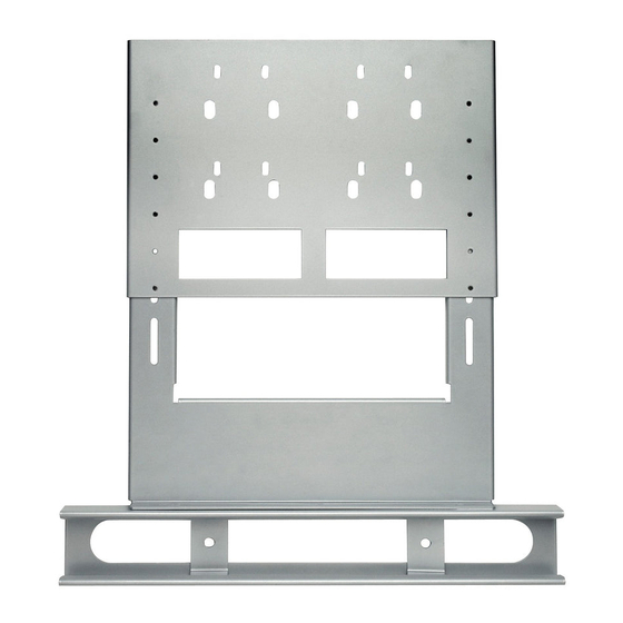
A center speaker mount
B interface bracket
C speaker attachment bracket
D M5 x 6 mm socket pin serrated
washer head screw
E M5 x 10mm socket pin screw
F
spacer
G 1/4 x 1.5" hex bolt
H 1/4" flat washer
I
3/8 x 1" bolt
J
flat washer
K tear drop locking tab
L 4 mm security allen wrench
Note: some parts may not appear exactly as illustrated.
B
H
L
MSA-101
QTY.
PART #
1
087-1041
1
087-1047
2
087-1042
4
510-1114
1
520-1063
1
540-1032
2
520-1096
2
540-9440
2
520-1242
2
540-9407
1
200-1871
1
560-9646
J
K
E
1 of 4
MAXIMUM LOAD CAPACITY:
MSA-101S
PART #
I
087-4041
087-4047
087-4042
510-1114
520-1063
540-1032
520-1096
540-9440
520-1242
540-9407
200-1871
560-9646
G
F
D
C
ISSUED: 12-19-05 SHEET #: 087-9013-4 05-10-06
Models: MSA-101,
MSA-101S
25.00 lb (11.4 kg)
A
Advertisement
Table of Contents

Related Manuals for peerless-AV MSA-101


Summary of Contents for peerless-AV MSA-101
- Page 1 Installation and Assembly - Multi-Channel Speaker Mount Models: MSA-101, MSA-101S for Boston Acoustics P400 or Polk Audio Center Channel MAXIMUM LOAD CAPACITY: 25.00 lb (11.4 kg) IMPORTANT! Read entire instruction sheet before you start installation and assembly. Parts List MSA-101...
- Page 2 Slide speaker attachment brackets (C) onto center speaker (A) mount as shown below. Installation with adapter plate Loosen screws on plasma adapter. Then place interface bracket (B) between plasma adapter and mount. Tighen screws on plasma adapter securly. Refer to adapter plate instructions for installation of screen. Skip to step 3.
- Page 3 Installation directly to screen Place interface bracket (B) between screen and mount. Attach interface bracket (B) to mount and screen using fasten- ers provided with mount. Refer to mount instructions for installation of screen. Tighten all screws securly. Note: For installation of tear drop locking tab (N) reference SP-850 instruction sheet. Note: Roll can be adjusted 1°...
- Page 4 Attach speaker to center speaker bracket (A) using two screws (I or G) and two washers (J). Adjust the speaker attachment brackets (C) to desired location and tighten screws. Note: For Boston Acoustics speakers use two 3/8 x 1" bolt (I) for Polk Audio use two 1/4 x 1.5" hex bolt (G). Note: Interface bracket not shown for clarity.
Need help?
Do you have a question about the MSA-101 and is the answer not in the manual?
Questions and answers