Table of Contents
Advertisement
Quick Links
CS6EP
Toyota
Thank you for purchasing the Beat-Sonic CS6EP Front Camera Selector. You have purchased
from Japan`s leading supplier of car audio interface adapters and accessories. Designed and
made in Japan, this product represents our commitment to quality and excellence. Please read
this manual carefully prior to installing this product to ensure correct operation.
■ Features
- Provides input connection for aftermarket front camera to factory display screen.
- Compatible with a wide range of 2014+ Toyota factory head units. Please visit the Beat-Sonic
website for the latest compatibility information.
- Selector button to activate front camera with programmable timer duration.
- Factory backup camera can be activated at any time without engaging reverse gear.
- Programmable to automatically display front camera at parking speed.
- Made in Japan.
■ Important
- Vehicles equipped with factory option navigation systems will experience temporary loss of
vehicle GPS accuracy and in some cases the vehicle may appear to travel backwards on the
map screen while the front camera is activated.
- This product requires the installation of a front camera with cables to pass through the
vehicles firewall. Accordingly, this product should be installed by an experienced motor
vehicle technician or automotive electrical professional.
- The user assumes all responsibility for any damages and/or injuries caused as a result of
improper installation.
■ Precautions
- Perform installation with patience and due care to prevent damage to this product or any part
of the vehicle.
- Do not use pointed objects or apply excessive pressure to the selector button.
- Ensure all connectors, cables and terminals are correctly secured and fully inserted. Loose
and/or improperly secured connectors will cause malfunction.
- Always grasp the connector plug when disconnecting the cable harness. Never disconnect
connectors by pulling on the harness wires as serious damage can occur.
- Do not disassemble, modify or attempt to repair this device.
- Beat-Sonic and its affiliates shall not be held responsible for any consequence, either directly
or otherwise, as a result of installing and/or using this product.
- Disconnect negative terminal of the vehicle battery prior to installation to prevent risk of short
circuit.
■ Contents
- Interface Module
- Connector Harness x 1
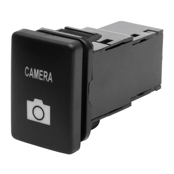
- Selector Button x 1
*Front Camera Not Included. Please purchase separately.
Connection Diagram
28-Pin
Connector
Factory
24-Pin
Head Unit
Connector
Head Unit appearance will vary
depending on model and grade
Vehicles with Navigation
Vehicles equipped with factory option
navigation systems will experience
temporary loss of vehicle GPS accuracy
and in some cases the vehicle may
appear to travel backwards on the map
screen while the front camera is
activated. Correct GPS location and
movement will return shortly after
returning to the normal screen.
Front Camera (Sold Separately)
Selector Button
NO:000001
Installation Manual
- RCA Video Cable 0.5m x 2
- Instruction Manual x 1
Connector Harness
RCA Video
Cable
FRONT CAM
BACK CAM
CAMERA SELECTOR
Interface
- CS -
Module
REV
SPD
IN
GND
REV
ACC
OUT
SW
OUT PUT
Installation
Disconnect the negative terminal of the vehicle battery and wait at least 90 seconds before
proceeding to prevent accidental airbag deployment.
1. Remove all necessary parts to gain access to the rear of the Multimedia Unit. The method
of dissasembly varies for each vehicle. If unsure please contact Beat-Sonic for model
specific instructions.
2017 Tacoma illustration shown.
Disassembly will vary according
to year and model of vehicle.
2. Connect the CS6EP 24-Pin and 28-Pin Connector Harness directly behind the
Display/Navigation Unit inline with the factory harness in a daisy chain configuration.
28-Pin Connector
24-Pin Connector
Connectors behind
factory Head Unit
3. Install the front camera ensuring that power for the front
camera is connected according to the manufactures instructions.
Connect the front camera video cable to the CS6EP module.
Caution
Take extra care not to damage
the vehicles wiring harness
grommet or cable when routing
camera cable through the firewall
4. Install the Selector Button in an easily accessible location for the driver.
5. Reconnect the battery terminal and test for correct operation before reassembling all parts.
Operation
Selector Button
Press button to display Front Camera
Press again to display Backup Camera (PTV Mode Enabled)
*Selector Button also used to effect changes in programmable settings.
Orange LED
LED flashes when front camera is activated.
LED is ON when reverse camera is activated.
LED is dimly illuminated with ACC ON and no cameras activated.
Camera Display Selection - Default Settings (PTV Mode Enabled)
Press the Selector Button to display the front camera. The front camera will turn off after
15 seconds and return to the normal display.
Pressing the Selector Button again before the 15 seconds has elapsed will display the backup
camera. The backup camera can be displayed at any time without having to select reverse
gear. The backup camera will turn off after 15 seconds and return to the normal display.
Pressing the Selector Button a 3rd time before the 15 seconds has elapsed will also return to
the normal display.
1st Press
Normal Display
* Selecting reverse gear will display the backup camera and override the front camera
display (if currently selected). Shifting out of reverse gear will then return to the normal
display screen regardless if the front camera was previously selected (default settings only).
Camera Display Selection - Optional Settings
2nd press Backup Camera PTV Mode (i.e. viewing of backup camera without selecting
reverse gear) can be disabled using the Backup Camera PTV Mode programmable settings
on the other side of this installation manual.
The duration of the camera display (default 15 seconds) can be changed using the Camera
Display Timer programming settings on the other side of this installation manual.
The front camera can be programmed to automatically display at low speeds to assist in
parking. See Front Camera Auto Turn-On programmable settings on the other side of this
installation manual.
Connector Harness
2nd Press
Front
Backup Camera
Camera
(PTV Mode Enabled)
3rd Press
28-Pin
Connector
24-Pin
Connector
Advertisement
Table of Contents

Related Manuals for Beat-Sonic CS6EP


Summary of Contents for Beat-Sonic CS6EP
- Page 1 - Provides input connection for aftermarket front camera to factory display screen. - Compatible with a wide range of 2014+ Toyota factory head units. Please visit the Beat-Sonic website for the latest compatibility information.
- Page 2 Backup Camera PTV Programmable Settings The CS6EP features Backup Camera Push to View (PTV) Mode that displays the Backup Camera at How to Enter Programming Mode any time without the need to select reverse gear. Pressing the Selector Button once will display the Front Camera.
Need help?
Do you have a question about the CS6EP and is the answer not in the manual?
Questions and answers