Table of Contents
Advertisement
Quick Links
Advertisement
Table of Contents

Related Manuals for Thermo Finnigan LTQ


Summary of Contents for Thermo Finnigan LTQ
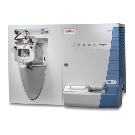
- Page 1 Finnigan ™ ™ Hardware Manual 97055-97013 Revision B...
- Page 2 This publication is not part of the Agreement of Sale between Thermo Electron Corporation and the purchaser of an LC/MS system. In the event of any conflict between the provisions of this document and those contained in Thermo Electron Corporation’s Terms and Conditions, the provisions of the Terms and Conditions...
- Page 3 For your convenience, you can fill in this form electronically at the website: www.thermo.com/lcms-techpubs. Customer Registration... Register now and receive all the privileges associated with being a Thermo Electron, Finnigan product user, including application reports and technical reports. Name _____________________________________________________________________________________________ Organization _______________________________________________________________________________________ Division/Dept.
- Page 4 From _______________________________ Place Stamp ____________________________________ Here ____________________________________ EDITOR, TECHNICAL PUBLICATIONS THERMO ELECTRON SAN JOSE 355 RIVER OAKS PARKWAY SAN JOSE, CA 95134-1991 UNITED STATES OF AMERICA fold...
- Page 5 Regulatory Compliance Thermo Electron San Jose performs complete testing and evaluation of its products to ensure full compliance with applicable domestic and international regulations. When your system is delivered to you, it meets all pertinent electromagnetic compatibility (EMC) and safety standards...
- Page 6 For your safety, and in compliance with international regulations, the physical handling of this Thermo Electron San Jose instrument requires a team effort for lifting and/or moving the instrument. This instrument is too heavy and/or bulky for one person alone to handle safely.
- Page 9 Electronic Equipment (WEEE) Directive 2002/96/EC. It is marked with the following symbol: Thermo Electron has contracted with one or more recycling/disposal companies in each EU Member State, and this product should be disposed of or recycled through them. Further information on Thermo Electron’s compliance with these Directives, the...
- Page 10 état membre de l’union européenne et ce produit devrait être collecté ou recyclé par celles-ci. Davantage d'informations sur la conformité de Thermo Electron à ces directives, les recycleurs dans votre pays et les informations sur les produits Thermo Electron qui peuvent aider la détection des substances sujettes à la directive RoHS sont...
-
Page 11: Table Of Contents
MS/MS Scan Mode ......................1-13 MSn Scan Mode ........................ 1-13 Scan Types ..........................1-14 Full Scan..........................1-14 Selected Ion Monitoring ....................1-15 Selected Reaction Monitoring ................... 1-16 Consecutive Reaction Monitoring..................1-16 ZoomScan.......................... 1-17 5IFSNP _______________________ Finnigan LTQ Hardware Manual _________________________ 8E86SQHGÁ6HQIHQ4SBHG... - Page 12 Checking the ESI Fused-Silica Sample Tube for Elongation ..........3-3 Checking the System Vacuum Levels................. 3-4 Removing the Septum, Reinstalling the Ion Sweep Cone, and Rechecking the Vacuum Levels ........................... 3-5 Checking the Disk Space ....................3-5 5IFSNP __________________________ Finnigan LTQ Hardware Manual _______________________ 8E86SQHGÁ6HQIHQ4SBHG...
- Page 13 Reassembling the Q00 Ion Guide..................4-26 Reinstalling the Q00 Ion Guide..................4-26 Reinstalling the Ion Source Interface ................4-27 Reinstalling the Ion Max Ion Source................. 4-27 Starting Up the System ...................... 4-27 5IFSNP _______________________ Finnigan LTQ Hardware Manual ________________________ 8E86SQHGÁ6HQIHQ4SBHG...
- Page 14 Resetting the Data System by Using the Windows XP Shutdown and Restart Procedure 5-11 Resetting the Data System by Using the Reset Button on the Personal Computer ...5-11 Turning Off Selected MS Detector Components..............5-13 5IFSNP _________________________ Finnigan LTQ Hardware Manual _______________________ 8E86SQHGÁ6HQIHQ4SBHG...
- Page 15 Printed Circuit Boards (PCBs) ..................7-16 Cables ..........................7-16 Fans............................ 7-18 Manuals............................ 7-18 Accessory Kit........................... 7-18 Metal Needle Kits ........................7-21 Fittings, Ferrules, Sample Loops, and Tubing ................. 7-21 Chemicals Kit........................... 7-22 5IFSNP _______________________ Finnigan LTQ Hardware Manual _________________________ 8E86SQHGÁ6HQIHQ4SBHG...
-
Page 17: Read This First
Read This First Welcome to the Thermo Electron, Finnigan™ LTQ™ system! The LTQ is a member of the Finnigan family of mass spectrometer (MS) detectors. This Finnigan LTQ Hardware Manual contains a description of the modes of operation and principle hardware components of your LTQ system. In addition, this manual provides step-by-step instructions for cleaning and maintaining your LTQ MS detector. -
Page 18: Changes To The Manual And Online Help
Editor, Technical Publications Thermo Electron San Jose 355 River Oaks Parkway San Jose, CA 95134-1991 U.S.A. You are encouraged to report errors or omissions in the text or index. Thank you. 5IFSNP viii ________________________ Finnigan LTQ Hardware Manual _______________________ 8E86SQHGÁ6HQIHQ4SBHG... -
Page 19: Abbreviations
(of a computer) cyclic redundancy check consecutive reaction monitoring <Ctrl> control key on the terminal keyboard depth dalton digital-to-analog converter direct current direct digital synthesizer DEP direct exposure probe data system digital signal processor 5IFSNP _________________________ Finnigan LTQ Hardware Manual______________________ 8E86SQHGÁ6HQIHQ4SBHG... - Page 20 Instrument Control Language inside diameter International Electrotechnical Commission IEEE Institute of Electrical and Electronics Engineers inch input/output kilo (10 , 1000) kilo (2 , 1024) KEGG Kyoto Encyclopedia of Genes and Genomes kilogram 5IFSNP __________________________ Finnigan LTQ Hardware Manual _______________________ 8E86SQHGÁ6HQIHQ4SBHG...
- Page 21 NCBI National Center for Biotechnology Information (USA) NIST National Institute of Standards and Technology (USA) outside diameter Ω pico (10 pascal printed circuit board proportional / integral / differential part number peak-to-peak voltage 5IFSNP _________________________ Finnigan LTQ Hardware Manual______________________ 8E86SQHGÁ6HQIHQ4SBHG...
- Page 22 Help, exponents are sometimes written with a caret (^) or with e notation because of design constraints in the online Help. For example: (in this manual) MS^n (in the online Help) (in this manual) 10^5 (in the online Help) 5IFSNP _________________________ Finnigan LTQ Hardware Manual _______________________ 8E86SQHGÁ6HQIHQ4SBHG...
-
Page 23: Typographical Conventions
Read This First 9tyytrfyÁESP ________________________________________________________Typographical Conventions Typographical Conventions Typographical conventions have been established for Thermo Electron San Jose manuals for the following: • Data input • Boxed information • Topic headings Data Input Throughout this manual, the following conventions indicate data input and output via the computer: •... -
Page 24: Boxed Information
CAUTION symbols and their meanings. • DANGER – laser-related hazards to human beings. It includes information specific to the class of laser involved. Each DANGER is accompanied by the international laser radiation symbol. 5IFSNP ________________________ Finnigan LTQ Hardware Manual _______________________ 8E86SQHGÁ6HQIHQ4SBHG... -
Page 25: Topic Headings
Topic Headings The following headings are used to show the organization of topics within a chapter: Chapter 1 Chapter Name 1.2 Second Level Topics Third Level Topics Fourth Level Topics Fifth Level Topics 5IFSNP _________________________ Finnigan LTQ Hardware Manual______________________ 8E86SQHGÁ6HQIHQ4SBHG... -
Page 26: Safety Precautions
Finnigan LTQ Hardware Manual. To avoid personal injury or damage to the instrument, do not perform any servicing other than that contained in the Finnigan LTQ Hardware Manual or related manuals unless you are qualified to do so. Shut Down the MS Detector and Disconnect It From Line Power Before You Service It. - Page 27 Thermo Electron San Jose Customer Support Engineer or before it is sent back to the factory for service.
-
Page 28: Solvent And Gas Purity Requirements
The LTQ MS detector uses helium as a collision gas. The helium should be high purity (99.995%). The required gas pressure is 135 ± 70 kPa (20 ± 10 psig). Thermo Electron has found that particulate filters are often contaminated and are therefore not recommended. -
Page 29: Service Philosophy
Thermo Electron Customer Support Engineer or similarly trained and qualified technical personnel. Level of Repair Thermo Electron’s service philosophy for the LTQ system calls for troubleshooting to the lowest part, assembly, PCB, or module listed in the Replaceable Parts chapter of this manual. -
Page 30: Reply Cards
The Customer Registration / Reader Survey card has two functions. First, when you return the card, you are placed on the Thermo Electron San Jose mailing list. As a member of this list, you receive application reports and technical reports in your area of interest, and you are notified of events of interest, such as user meetings. -
Page 31: Introduction
Chapter 1 Introduction The LTQ™ is a member of the Finnigan™ family of mass spectrometer (MS) detectors. The Finnigan LTQ is an advanced analytical instrument that includes a syringe pump, a divert/inject valve, an MS detector, and the ® Xcalibur data system. - Page 32 This chapter provides an overview of the LTQ. Specific topics covered are as follows: • Ion polarity modes • Ionization techniques • Scan modes • Scan types • Data types • Experiment types 5IFSNP _______________________ Finnigan LTQ Hardware Manual _______________________ 8E86SQHGÁ6HQIHQ4SBHG...
-
Page 33: Ion Polarity Modes
You can choose the ion polarity mode and ionization technique to obtain maximum sensitivity for the particular analysis of interest. 5IFSNP _______________________ Finnigan LTQ Hardware Manual ______________________ 8E86SQHGÁ6HQIHQ4SBHG... -
Page 34: Ionization Techniques
1990, 9, 37; Smith, R. D.; Loo, J. A.; Edmonds, C. G.; Barinaga, C. J.; Udseth, H. R. Anal. Chem. 1990, 62, 882; Ikonomou, M. G.; Blades, A. T.; Kebarle, P. Anal. Chem. 1991, 63, 1989. 5IFSNP _______________________ Finnigan LTQ Hardware Manual _______________________ 8E86SQHGÁ6HQIHQ4SBHG... - Page 35 Figure 1-3 shows the steps in the formation of ions from highly charged droplets, and the relationship between the ESI probe and the ion transfer capillary. 5IFSNP _______________________ Finnigan LTQ Hardware Manual ______________________ 8E86SQHGÁ6HQIHQ4SBHG...
- Page 36 In the case of higher molecular weight proteins or peptides, the resulting mass spectrum consists typically of a series of peaks corresponding to a distribution of multiply charged analyte ions. 5IFSNP _______________________ Finnigan LTQ Hardware Manual _______________________ 8E86SQHGÁ6HQIHQ4SBHG...
-
Page 37: Atmospheric Pressure Chemical Ionization
APCI is a gas phase ionization technique. Therefore, the gas phase acidities and basicities of the analyte and solvent vapor play an important role in the APCI process. 5IFSNP _______________________ Finnigan LTQ Hardware Manual ______________________ 8E86SQHGÁ6HQIHQ4SBHG... - Page 38 2000 u. APCI is a very robust ionization technique. It is not affected by minor changes in most variables such as changes in buffer or buffer strength. Figure 1-4 shows the APCI process in the positive ion polarity mode. 5IFSNP _______________________ Finnigan LTQ Hardware Manual _______________________ 8E86SQHGÁ6HQIHQ4SBHG...
- Page 39 This is because the negative ion polarity mode sometimes generates less chemical noise than does the positive mode. Thus, selectivity might be better in the negative ion mode than in the positive ion mode. 5IFSNP _______________________ Finnigan LTQ Hardware Manual ______________________ 8E86SQHGÁ6HQIHQ4SBHG...
-
Page 40: Atmospheric Pressure Photoionization
LC/MS are not ionized because their ionization potentials are greater than the photon energy. The result is selective ionization of analyte vs. background. See Figure 1-5 and Figure 1-6. 5IFSNP 1-10 ______________________ Finnigan LTQ Hardware Manual _______________________ 8E86SQHGÁ6HQIHQ4SBHG... - Page 41 MeOH, AcCN MeOH, AcCN Drugs Drugs Drugs Chlorinated-solvents Chlorinated-solvents Steroids Steroids O, CO O, CO Ionized Not Ionized Ionized Ionized Ionized Ionized Threshold Threshold Threshold Figure 1-6. Illustration of selective photoionization 5IFSNP 1-11 _______________________ Finnigan LTQ Hardware Manual _____________________ 8E86SQHGÁ6HQIHQ4SBHG...
-
Page 42: Nanospray Ionization
30 min. Stable mass spectra can be obtained for very small amounts of biomolecules such as proteins, peptides, oligonucleotides, and oligosaccharides. For more information on NSI, refer to the manual that came with the NSI source. 5IFSNP 1-12 ______________________ Finnigan LTQ Hardware Manual _______________________ 8E86SQHGÁ6HQIHQ4SBHG... -
Page 43: Scan Power And Scan Modes
(with n = 1) or to two stages of mass analysis (with n = 2).] An MS scan can be either a full scan experiment or a consecutive reaction monitoring (CRM) experiment (see below). 5IFSNP 1-13 _______________________ Finnigan LTQ Hardware Manual _____________________ 8E86SQHGÁ6HQIHQ4SBHG... -
Page 44: Scan Types
Then, you might use SIM or SRM to do routine quantitative analysis of the compound. 5IFSNP 1-14 ______________________ Finnigan LTQ Hardware Manual _______________________ 8E86SQHGÁ6HQIHQ4SBHG... -
Page 45: Selected Ion Monitoring
SIM achieves greater speed because only a few ions of interest are monitored; regions of the spectrum that are empty or have no ions of interest are not monitored. 5IFSNP 1-15 _______________________ Finnigan LTQ Hardware Manual _____________________ 8E86SQHGÁ6HQIHQ4SBHG... -
Page 46: Selected Reaction Monitoring
Product ions of one mass-to-charge ratio are then selected and all other ions are ejected from the mass analyzer. The selected product ions now become the new parent ions for the next stage of mass analysis. The new 5IFSNP 1-16 ______________________ Finnigan LTQ Hardware Manual _______________________ 8E86SQHGÁ6HQIHQ4SBHG... -
Page 47: Zoomscan
You can conduct a ZoomScan analysis of up to ten ions by specifying the mass-to-charge ratios of the ions. 5IFSNP 1-17 _______________________ Finnigan LTQ Hardware Manual _____________________ 8E86SQHGÁ6HQIHQ4SBHG... -
Page 48: Data Types
15 sampling intervals. In general, the centroid scan data type is used for data acquisition because the scan speed is faster (but the resolution is lower) and the disk space requirements are smaller. Data processing is also much faster for centroid data. 5IFSNP 1-18 ______________________ Finnigan LTQ Hardware Manual _______________________ 8E86SQHGÁ6HQIHQ4SBHG... -
Page 49: Experiment Types
Instrument Setup window, and then save it in an Instrument Method (.meth) file. Note. Procedures for these experiments are beyond the scope of this Finnigan LTQ Hardware Manual. If you need more information, refer to online Help. General MS or MS... -
Page 50: Data-Dependent Experiments
MS or MS ion signal. Whatever threshold values you choose should accomplish the isolation of your parent ions of interest. 5IFSNP 1-20 ______________________ Finnigan LTQ Hardware Manual _______________________ 8E86SQHGÁ6HQIHQ4SBHG... -
Page 51: Ion Mapping Experiments
An Ion Mapping experiment can help to identify automatically which parent ions were fragmented to yield a specified product ion. The experiment “maps” one or more parent ions by using the information from product ion scans. 5IFSNP 1-21 _______________________ Finnigan LTQ Hardware Manual _____________________ 8E86SQHGÁ6HQIHQ4SBHG... -
Page 52: Ion Tree Experiments
MS . The LTQ automates the collection of data by deciding what actions need to occur next for the experiment to progress. 5IFSNP 1-22 ______________________ Finnigan LTQ Hardware Manual _______________________ 8E86SQHGÁ6HQIHQ4SBHG... - Page 53 The results of a Data-Dependent Ion Tree experiment can be viewed in the Xcalibur Qual Browser window. The results are displayed as a structure tree that originates from a particular parent ion. 5IFSNP 1-23 _______________________ Finnigan LTQ Hardware Manual _____________________ 8E86SQHGÁ6HQIHQ4SBHG...
-
Page 55: Functional Description
The data system provides the primary LTQ user interface. 5IFSNP _______________________ Finnigan LTQ Hardware Manual ______________________ 8E86SQHGÁ6HQIHQ4SBHG... - Page 56 Functional Description @@@@@@@@@@@@@@@@@@@@@@@@@@@@@@@@@@@@@@@@@@@@@@@@@@@@@@@@@@@@@@@@@@@@@@@@ 9tyytrfyÁESP Figure 2-1. Functional block diagram of the LTQ system. The broad, single-headed arrows represent the flow of sample molecules through the instrument. The narrow, double-headed arrows represent electrical connections. 5IFSNP _______________________ Finnigan LTQ Hardware Manual _______________________ 8E86SQHGÁ6HQIHQ4SBHG...
-
Page 57: Autosampler
LC/MS analyses. Note. For other autosamplers, LTQ provides contact closure Start/Stop signals. Refer to Finnigan LTQ Getting Connected for information on connecting an autosampler to the LTQ by contact closure Start/Stop signals. You can configure the Xcalibur data system for your autosampler from the data system computer. -
Page 58: Liquid Chromatograph
LC and enters the MS detector. Thermo Electron (Finnigan Surveyor MS, Surveyor LC, TSP P2000, TSP P4000), and Agilent (1100) LCs (and the corresponding UV detectors) can be controlled directly from the LTQ data system computer. Refer to Finnigan LTQ Getting Connected for information on connecting an LC to the LTQ. -
Page 59: Syringe Pump
Liquid flows out of the syringe needle and into the sample transfer line as the plunger is depressed. The syringe is held in place by a syringe holder. Refer to Finnigan LTQ Getting Started for instructions on setting up the syringe pump. -
Page 60: Divert/Inject Valve
MS detector and waste when the valve is in the divert valve configuration, or switch between load and inject modes when the valve is in the loop injector configuration. Divert/Inject Valve Sample Loop Syringe Port Figure 2-3. Divert/inject valve 5IFSNP _______________________ Finnigan LTQ Hardware Manual _______________________ 8E86SQHGÁ6HQIHQ4SBHG... -
Page 61: Ms Detector
In the Normal condition, the temperature in the MS detector is less than 37 °C and its +5 V dc supply level is between +4.98 and +5.25 V dc. The Power LED is illuminated solid green. 5IFSNP _______________________ Finnigan LTQ Hardware Manual ______________________ 8E86SQHGÁ6HQIHQ4SBHG... - Page 62 API source, mass analyzer, and ion detection system). The LED labeled Scanning flashes blue whenever the MS detector is On and scanning ions. Figure 2-4. Front panel LEDs of the MS detector 5IFSNP _______________________ Finnigan LTQ Hardware Manual _______________________ 8E86SQHGÁ6HQIHQ4SBHG...
- Page 63 Note. To shut off all power to the MS detector in an emergency, place the main power circuit breaker switch (labeled Main Power) in the Off (O) position. Do not use the electronics service switch . 5IFSNP _______________________ Finnigan LTQ Hardware Manual ______________________ 8E86SQHGÁ6HQIHQ4SBHG...
-
Page 64: Api Source
API source using either the electrospray ionization (ESI), atmospheric pressure chemical ionization (APCI), atmospheric pressure photoionization (APPI), or nanospray ionization (NSI) technique. The API source consists of: ™ • Ion Max ion source • Ion source interface 5IFSNP 2-10 ______________________ Finnigan LTQ Hardware Manual _______________________ 8E86SQHGÁ6HQIHQ4SBHG... - Page 65 Minor adjustment of the probe position in the X, Y, and Z dimensions is allowed, with marked adjustments to allow for freedom in probe position 5IFSNP 2-11 _______________________ Finnigan LTQ Hardware Manual _____________________ 8E86SQHGÁ6HQIHQ4SBHG...
- Page 66 The voltage monitoring circuit detects shorting failures. The overtemperature portion of the circuit is intended to function as a thermal limit switch to prevent the 5IFSNP 2-12 ______________________ Finnigan LTQ Hardware Manual _______________________ 8E86SQHGÁ6HQIHQ4SBHG...
- Page 67 Lens L0 Ion Transfer Cone Capillary Vent Prevent Ball Vacuum Manifold Quadrupole Tube Lens Heater Block Heater Cartridge Figure 2-8. Cross sectional view of the ion source interface and Q00 ion guide 5IFSNP 2-13 _______________________ Finnigan LTQ Hardware Manual _____________________ 8E86SQHGÁ6HQIHQ4SBHG...
- Page 68 Figure 2-9. Internal (under vacuum) components of the MS detector 5IFSNP 2-14 ______________________________________ Finnigan LTQ Hardware Manual_________________________________________________ 8E86SQHGÁ6HQIHQ4SBHG...
-
Page 69: Ion Optics
Q00 is so high, ions typically have zero kinetic energy when they emerge from Q00. There must be a downhill potential gradient for them to enter Q0. 5IFSNP 2-15 _______________________ Finnigan LTQ Hardware Manual _____________________ 8E86SQHGÁ6HQIHQ4SBHG... -
Page 70: Mass Analyzer
In each quadrupole rod section, rods opposite each other in the array are connected electrically. Thus, the four rods of each section can be considered to be two pairs of two rods each. 5IFSNP 2-16 ______________________ Finnigan LTQ Hardware Manual _______________________ 8E86SQHGÁ6HQIHQ4SBHG... - Page 71 (1.2 MHz) and of variable amplitude (0 to 10,000 V peak-to-peak). Because the frequency of this ac voltage is in the radio frequency (RF) range, it is referred to as the main RF voltage. The application of the main RF voltage to 5IFSNP 2-17 _______________________ Finnigan LTQ Hardware Manual _____________________ 8E86SQHGÁ6HQIHQ4SBHG...
- Page 72 RF voltage is applied to the exit rods to fragment parent ions into product ions. The resonance excitation RF voltage is not strong enough to eject an ion from the mass analyzer. 5IFSNP 2-18 ______________________ Finnigan LTQ Hardware Manual _______________________ 8E86SQHGÁ6HQIHQ4SBHG...
- Page 73 (n > 1) full scan analysis, the resonance excitation RF voltage applied to the endcap electrodes drives parent ions into the helium atoms. After gaining sufficient internal energy from the resulting collisions, the parent ion dissociates into one or more product ions. 5IFSNP 2-19 _______________________ Finnigan LTQ Hardware Manual _____________________ 8E86SQHGÁ6HQIHQ4SBHG...
- Page 74 RF voltage is applied to the exit rods to facilitate ejection. As the main RF voltage is increased, ions of greater and greater mass-to-charge 5IFSNP 2-20 ______________________ Finnigan LTQ Hardware Manual _______________________ 8E86SQHGÁ6HQIHQ4SBHG...
-
Page 75: Ion Detection Systems
Due to the funnel shape of the cathode, the ejected electrons do not travel far before they again strike the inner surface of the cathode, thereby causing the emission of more electrons. 5IFSNP 2-21 _______________________ Finnigan LTQ Hardware Manual _____________________ 8E86SQHGÁ6HQIHQ4SBHG... - Page 76 Refer to the topic Ion Detection System Electronic Assemblies on page 2-38. EXIT ROD Figure 2-11. Cross sectional view of the ion detection system, showing the electron multiplier and the conversion dynode 5IFSNP 2-22 ______________________ Finnigan LTQ Hardware Manual _______________________ 8E86SQHGÁ6HQIHQ4SBHG...
-
Page 77: Vacuum System And Inlet Gasses Hardware
The principal components of the vacuum system include the following (see Figure 2-12): • Vacuum manifold • Turbomolecular pump • Forepump • ® Convectron gauge • Ion gauge 5IFSNP 2-23 _______________________ Finnigan LTQ Hardware Manual _____________________ 8E86SQHGÁ6HQIHQ4SBHG... - Page 78 Damping gas inlet assembly • Sheath gas valve • Auxiliary gas valve • Sweep gas valve A functional block diagram of the vacuum system and inlet gasses hardware is shown in Figure 2-13. 5IFSNP 2-24 ______________________ Finnigan LTQ Hardware Manual _______________________ 8E86SQHGÁ6HQIHQ4SBHG...
- Page 79 10 Torr by the high vacuum port of the turbomolecular pump. The turbomolecular pump in turn discharges into the rotary-vane pump through the foreline. 5IFSNP 2-25 _______________________ Finnigan LTQ Hardware Manual _____________________ 8E86SQHGÁ6HQIHQ4SBHG...
- Page 80 O-ring provides a vacuum-tight seal between the top cover plate and the vacuum manifold. The top cover plate and its attached assemblies are shown in Figure 2-15 and Figure 2-16. 5IFSNP 2-26 ______________________ Finnigan LTQ Hardware Manual _______________________ 8E86SQHGÁ6HQIHQ4SBHG...
- Page 81 • Two feedthroughs for the high voltage for the cathodes of the electron multipliers • A feedthrough for the ion current signal from the dual anode of the electron multipliers 5IFSNP 2-27 _______________________ Finnigan LTQ Hardware Manual _____________________ 8E86SQHGÁ6HQIHQ4SBHG...
- Page 82 An 300 L/s interstage inlet about half way down the rotor stack, which evacuates the Q0 ion guide chamber • A 25 L/s third inlet in the molecular drag section of the pump, which evacuates the Q00 ion guide chamber 5IFSNP 2-28 ______________________ Finnigan LTQ Hardware Manual _______________________ 8E86SQHGÁ6HQIHQ4SBHG...
- Page 83 The pump has a maximum displacement of 650 L/min and maintains a minimum pressure of approximately 100 Pa (1 Torr). 5IFSNP 2-29 _______________________ Finnigan LTQ Hardware Manual _____________________ 8E86SQHGÁ6HQIHQ4SBHG...
- Page 84 When power to the vent valve solenoid is shut off, the vent valve opens and the manifold is vented to filtered air. The vent valve closes after power is restored to the MS detector. 5IFSNP 2-30 ______________________ Finnigan LTQ Hardware Manual _______________________ 8E86SQHGÁ6HQIHQ4SBHG...
-
Page 85: Cooling Fans
MS detector. The exhaust air is expelled from the vent slots on the sides of the MS detector. Caution. To ensure proper cooling, the MS detector must always be operated with its covers in place. 5IFSNP 2-31 _______________________ Finnigan LTQ Hardware Manual _____________________ 8E86SQHGÁ6HQIHQ4SBHG... -
Page 86: Electronic Assemblies
The electronics service switch is a circuit breaker that allows service of the non-vacuum system components of the MS detector with the vacuum system still in operation (see Figure 2-6). In the Service position the switch removes 5IFSNP 2-32 ______________________ Finnigan LTQ Hardware Manual _______________________ 8E86SQHGÁ6HQIHQ4SBHG... - Page 87 APCI mode, the current is regulated. The conversion dynode / electron multiplier power supply provides ± 15 kV to the conversion dynodes and 0 to –2.5 KV to the electron multipliers in the ion detection system. 5IFSNP 2-33 _______________________ Finnigan LTQ Hardware Manual _____________________ 8E86SQHGÁ6HQIHQ4SBHG...
- Page 88 +180 V LENSES, GAS FLOW ANALOG DC OFFSETS, GAUGE VALVES Q00, Q0, Q1 RF Figure 2-18. Functional block diagram of the Power Entry Module and power distribution of the MS detector 5IFSNP 2-34 ______________________ Finnigan LTQ Hardware Manual _______________________ 8E86SQHGÁ6HQIHQ4SBHG...
- Page 89 The APCI vaporizer heater/sensor control circuit controls the temperature of the APCI vaporizer via a thermocouple sensor. It also provides 230 V ac line voltage to the heater in the APCI vaporizer. 5IFSNP 2-35 _______________________ Finnigan LTQ Hardware Manual _____________________ 8E86SQHGÁ6HQIHQ4SBHG...
- Page 90 Q00 and Q0 quadrupoles, and Q1 octapole. They also produce the ion isolation waveform voltage, resonance excitation RF voltage, and resonance ejection RF voltage that are applied to the exit rods of the mass analyzer. 5IFSNP 2-36 ______________________ Finnigan LTQ Hardware Manual _______________________ 8E86SQHGÁ6HQIHQ4SBHG...
- Page 91 RF for the exit rods. The embedded computer, which is also part of the Digital PCB, is where the computations that are required to produce the waveforms take place. 5IFSNP 2-37 _______________________ Finnigan LTQ Hardware Manual _____________________ 8E86SQHGÁ6HQIHQ4SBHG...
- Page 92 The integrated voltage is then passed to the Signal/Power Distribution PCB where it is processed and sent to the data system. 5IFSNP 2-38 ______________________ Finnigan LTQ Hardware Manual _______________________ 8E86SQHGÁ6HQIHQ4SBHG...
- Page 93 Functional Description 9tyytrfyÁESP ___________________________________________________________________ MS Detector DATA POWER/SIGNAL ANALOG PCB SYSTEM DISTRIBUTION PCB ELECTROMETER ELECTRON MULTIPLIER CONVERSION DYNODE POWER SUPPLY Figure 2-19. Functional block diagram of the ion detection system electronic assemblies 5IFSNP 2-39 _______________________ Finnigan LTQ Hardware Manual _____________________ 8E86SQHGÁ6HQIHQ4SBHG...
-
Page 94: Data System
6 GB hard drive (NTFS) or more recommended • CD-ROM drive • Video card and monitor capable of 1024 × 768 (XGA) resolution and 65,536 colors • Microsoft Windows XP • Microsoft Office XP 5IFSNP 2-40 ______________________ Finnigan LTQ Hardware Manual _______________________ 8E86SQHGÁ6HQIHQ4SBHG... -
Page 95: Data System / Ms Detector / Lc Interface
RS232 connection. A synchronization cable assembly is used to coordinate the run control signals between the LC modules and the MS detector. Refer to Finnigan LTQ Getting Connected for information on connecting the LTQ with other LC modules. -
Page 96: Data System / Local Area Network Interface
You set up the printer from the Print Setup dialog box. To open the Print Setup dialog box, choose File > Print Setup in any window. 5IFSNP 2-42 ______________________ Finnigan LTQ Hardware Manual _______________________ 8E86SQHGÁ6HQIHQ4SBHG... -
Page 97: Daily Operation
(that is, optimize the tune and calibration parameters) perhaps once a quarter. Refer to the Automatic Tuning and Calibrating in the ESI/MS Mode chapter in Finnigan LTQ Getting Started for a procedure for tuning and calibrating the LTQ. To check the tuning and calibration, follow the procedure described in the topic Testing the Operation of the MS Detector in the ESI/MS Mode in Finnigan LTQ Getting Started. -
Page 98: Things To Do Before Operating The Ltq
MS detector is On could be unsafe. LTQ displays a popup message if the nitrogen pressure is too low. Go on to the next topic: Checking the ESI Fused-Silica Sample Tube for Elongation. 5IFSNP _______________________ Finnigan LTQ Hardware Manual _______________________ 8E86SQHGÁ6HQIHQ4SBHG... -
Page 99: Checking The Esi Fused-Silica Sample Tube For Elongation
8. Reinstall the ESI probe as described in the section Installing the ESI Probe on page 2-9 of the Finnigan Ion Max API Source Hardware Manual. Go on to the next topic: Checking the System Vacuum Levels. 5IFSNP _______________________ Finnigan LTQ Hardware Manual ______________________ 8E86SQHGÁ6HQIHQ4SBHG... -
Page 100: Checking The System Vacuum Levels
Pay particular attention to fittings that have been changed recently or to fittings that have been subjected to heating and cooling. Make sure that the cover plates of the vacuum manifold are properly seated. 5IFSNP _______________________ Finnigan LTQ Hardware Manual _______________________ 8E86SQHGÁ6HQIHQ4SBHG... -
Page 101: Checking The Disk Space
First, copy files to the backup medium. After you have copied the files, you can delete them from the hard disk. 5IFSNP _______________________ Finnigan LTQ Hardware Manual ______________________ 8E86SQHGÁ6HQIHQ4SBHG... -
Page 102: Things To Do After Operating The Ltq
In the APCI Source dialog box, enter 500 in the Vaporizer Temperature text box. c. Set the sheath gas flow rate to 30: In the APCI Source dialog box, enter 30 in the Sheath Gas Flow Rate text box. 5IFSNP _______________________ Finnigan LTQ Hardware Manual _______________________ 8E86SQHGÁ6HQIHQ4SBHG... - Page 103 LC to the API source, as follows. Leave the API source (including the APCI vaporizer, sheath gas, and auxiliary gas) on for an additional 5 min. (or Pump Off or Stop Pump) to stop the LC pump. Click on 5IFSNP _______________________ Finnigan LTQ Hardware Manual ______________________ 8E86SQHGÁ6HQIHQ4SBHG...
-
Page 104: Placing The System In Standby Condition
API source. To turn off the flow of liquid from the LC to the API source, do the following: a. Choose Start > Programs > Xcalibur > LTQ Tune to open the LTQ Tune Plus window. 5IFSNP _______________________ Finnigan LTQ Hardware Manual _______________________ 8E86SQHGÁ6HQIHQ4SBHG... - Page 105 Refer to topic Removing and Cleaning the Ion Transfer Capillary on page 4-8. c. Clean the ion sweep cone as follows: 5IFSNP _______________________ Finnigan LTQ Hardware Manual ______________________ 8E86SQHGÁ6HQIHQ4SBHG...
- Page 106 The gas inlet on the ion sweep cone is placed in this port. See Figure 3-1 and Figure 3-2. Sweep Supply Port Spray Cone Figure 3-1. Sweep gas supply port in the API cone seal 5IFSNP 3-10 ______________________ Finnigan LTQ Hardware Manual _______________________ 8E86SQHGÁ6HQIHQ4SBHG...
-
Page 107: Purging The Oil In The Rotary-Vane Pump
API source. To turn off the flow of liquid from the LC to the API source, do the following: a. Choose Start > Programs > Xcalibur > LTQ Tune to open the LTQ Tune Plus window. 5IFSNP 3-11 _______________________ Finnigan LTQ Hardware Manual _____________________ 8E86SQHGÁ6HQIHQ4SBHG... -
Page 108: Emptying The Solvent Waste Bottle
The solvent level in the solvent waste bottle should be checked on a daily basis. If necessary, empty the solvent waste bottle. Dispose of the solvent waste in accordance with local and federal regulations. 5IFSNP 3-12 ______________________ Finnigan LTQ Hardware Manual _______________________ 8E86SQHGÁ6HQIHQ4SBHG... -
Page 109: Ms Detector Maintenance
Procedures are also presented for replacing the API sample tube, ion transfer capillary, and API source, ion optics, and mass analyzer assemblies. Routine and less frequent MS detector maintenance procedures are listed in Table 4-1. 5IFSNP _______________________ Finnigan LTQ Hardware Manual ______________________ 8E86SQHGÁ6HQIHQ4SBHG... - Page 110 Finnigan Ion Max API source Source Hardware Manual Q0 ion guide Clean Q0 quadrupole As needed Page 4-28 and intermultiple lens Q1 ion guide Clean Q1 octapole and As needed Page 4-28 gate lens 5IFSNP _______________________ Finnigan LTQ Hardware Manual _______________________ 8E86SQHGÁ6HQIHQ4SBHG...
- Page 111 Replace PCB If PCB fails Diagnostics and PCB and Assembly Replacement chapter Frequency depends on analytical conditions We recommend that this maintenance procedure be performed by a Thermo Electron Field Service Engineer 5IFSNP _______________________ Finnigan LTQ Hardware Manual ______________________ 8E86SQHGÁ6HQIHQ4SBHG...
- Page 112 Always wear clean, lint-free gloves when handling the components of the API source, ion guides, mass analyzer, and ion detection system. • Always place the components on a clean, lint-free surface. • Never overtighten a screw or use excessive force. 5IFSNP _______________________ Finnigan LTQ Hardware Manual _______________________ 8E86SQHGÁ6HQIHQ4SBHG...
-
Page 113: Tools And Supplies
Nitric acid, dilute CAUTION. As with all chemicals, solvents and reagents should be stored and handled according to standard safety procedures and should be disposed of according to local and federal regulations. 5IFSNP _______________________ Finnigan LTQ Hardware Manual ______________________ 8E86SQHGÁ6HQIHQ4SBHG... -
Page 114: Frequency Of Cleaning
Clean the quadrupole and lens of the Q00 ion guide • Clean the quadrupole and lens of the Q0 ion guide and the octapole and lens of the Q1 ion guide • Clean the mass analyzer 5IFSNP _______________________ Finnigan LTQ Hardware Manual _______________________ 8E86SQHGÁ6HQIHQ4SBHG... -
Page 115: Api Source Maintenance
API probe with a 50:50 methanol:water solution from the LC. To clean the ion 5IFSNP _______________________ Finnigan LTQ Hardware Manual ______________________ 8E86SQHGÁ6HQIHQ4SBHG... -
Page 116: Removing And Cleaning The Ion Transfer Capillary
2. Place the electronics service switch (located on the right side of the MS detector) in the Service position to turn off the non-vacuum system voltages. CAUTION. Make sure that the LTQ electronics service switch is in the Service position before you proceed. 5IFSNP _______________________ Finnigan LTQ Hardware Manual _______________________ 8E86SQHGÁ6HQIHQ4SBHG... - Page 117 Replace it if necessary. Spray Cone Ion Sweep 0.3-in. ID O-Ring Cone Ion Transfer Capillary Figure 4-1. Ion sweep cone, ion transfer capillary, O-ring, and spray cone of the ion source interface 5IFSNP _______________________ Finnigan LTQ Hardware Manual ______________________ 8E86SQHGÁ6HQIHQ4SBHG...
-
Page 118: Maintaining The Api Probes
50:50 HPCL-grade methanol:distilled water solution from the LC through the APCI probe. Refer to the topic Flushing the Sample Transfer Line, Sample Tube, and API Probe on page 3-7. 5IFSNP 4-10 ______________________ Finnigan LTQ Hardware Manual _______________________ 8E86SQHGÁ6HQIHQ4SBHG... -
Page 119: Maintaining The Photomate Light Source
Shut down and vent the system as described in the topic Shutting Down the System Completely in the System Shutdown, Startup, and Reset chapter. Wait several minutes for the LTQ to vent. Go on to the next topic: Removing the Ion Max Ion Source. 5IFSNP 4-11 _______________________ Finnigan LTQ Hardware Manual _____________________ 8E86SQHGÁ6HQIHQ4SBHG... - Page 120 3. Remove the ion source housing by pulling straight off of the ion source mount assembly, and place the housing in a safe location for temporary storage. Go on to the next topic: Removing the Ion Source Interface. 5IFSNP 4-12 ______________________ Finnigan LTQ Hardware Manual _______________________ 8E86SQHGÁ6HQIHQ4SBHG...
- Page 121 To clean the tube lens and skimmer proceed as follows: CAUTION. Wait for the ion source interface to cool to ambient temperature before you disassemble it. 5IFSNP 4-13 _______________________ Finnigan LTQ Hardware Manual _____________________ 8E86SQHGÁ6HQIHQ4SBHG...
- Page 122 7. Clean the skimmer inside and out with HPLC-grade methanol and a cotton-tipped applicator (swab). Tube Lens Plunger Ball Skimmer Plunger Ball Contact Ring Tube Lens Skimmer Figure 4-4. Rear of the ion source interface showing the tube lens and skimmer 5IFSNP 4-14 ______________________ Finnigan LTQ Hardware Manual _______________________ 8E86SQHGÁ6HQIHQ4SBHG...
- Page 123 1 through 4. To replace other ion source interface component, refer to the exploded diagrams shown in Figure 4-5 and Figure 4-6. Go on to the next topic: Reinstalling the Ion Source Interface. 5IFSNP 4-15 _______________________ Finnigan LTQ Hardware Manual _____________________ 8E86SQHGÁ6HQIHQ4SBHG...
- Page 124 Mount Cage 2.033-in. O-Rings Spray Cone Ion Sweep Contact Socket Guide Pin Cone Graphite Seal Spray Cone Seal 0.3-in. O-Ring Ion Transfer Capillary Figure 4-5. Exploded view of the ion source interface (front) 5IFSNP 4-16 ______________________________________ Finnigan LTQ Hardware Manual_________________________________________________ 8E86SQHGÁ6HQIHQ4SBHG...
- Page 125 Capillary Heater Mounting Cage 2.625-in. O-Ring Capillary Heater Plunger Balls Vented Screws Contact Ring Tube Lens Skimmer Figure 4-6. Exploded view of the ion source interface (rear) 5IFSNP 4-17 _____________________________________________ Finnigan LTQ Hardware Manual ________________________________________ 8E86SQHGÁ6HQIHQ4SBHG...
- Page 126 9tyytrfyÁESP API Source Maintenance RTD (Right) RTD Ret. (Left) Heater 1 Ret. Heater 2 Heater 1 Heater 2 Ret. Pin #1 #2 Figure 4-7. Wiring diagram for the ion source interface 5IFSNP 4-18 ______________________ Finnigan LTQ Hardware Manual _______________________ 8E86SQHGÁ6HQIHQ4SBHG...
- Page 127 Attach the free end of the hose to a waste container. Ideally, the waste container should be vented to a fume exhaust system. Go on to the next topic: Starting Up the System. 5IFSNP 4-19 _______________________ Finnigan LTQ Hardware Manual _____________________ 8E86SQHGÁ6HQIHQ4SBHG...
- Page 128 MS Detector Maintenance @@@@@@@@@@@@@@@@@@@@@@@@@@@@@@@@@@@@@@@@@@@@@@@@@@@@@ 9tyytrfyÁESP API Source Maintenance Ion Source Housing Locking Levers Guide Ion Source Housing Pin Holes Drain Figure 4-8. Rear view of the Ion Max ion source housing 5IFSNP 4-20 ______________________ Finnigan LTQ Hardware Manual _______________________ 8E86SQHGÁ6HQIHQ4SBHG...
- Page 129 Ion source mount showing ion source housing guide pins Starting Up the System Start up the system as described in the topic Starting Up the System After a Complete Shutdown in the System Shutdown, Startup, and Reset chapter. 5IFSNP 4-21 _______________________ Finnigan LTQ Hardware Manual _____________________ 8E86SQHGÁ6HQIHQ4SBHG...
-
Page 130: Cleaning The Q00 Ion Guide
Q00 ion guide. Remove the Ion Max ion source from the front of the MS detector as described in the topic Removing the Ion Max Ion Source on page 4-12. Go on to the next topic: Removing the Ion Source Interface. 5IFSNP 4-22 ______________________ Finnigan LTQ Hardware Manual _______________________ 8E86SQHGÁ6HQIHQ4SBHG... -
Page 131: Removing The Ion Source Interface
3. Carefully remove the Q00 ion guide and place it on a clean surface. Vacuum Manifold Q00 Ion Guide Assembly Socket Head Screws Ion Source Interface Figure 4-10. Q00 ion guide assembly removal .Go on to the next topic: Disassembling the Q00 Ion Guide. 5IFSNP 4-23 _______________________ Finnigan LTQ Hardware Manual _____________________ 8E86SQHGÁ6HQIHQ4SBHG... -
Page 132: Disassembling The Q00 Ion Guide
(The Q00 quadrupole is secured to the Q00 ion guide cage by plunger balls.) Go on to the next topic: Cleaning the Q00 Ion Guide Components. Figure 4-11. Q00 quadrupole and lens L0 wiring 5IFSNP 4-24 ______________________ Finnigan LTQ Hardware Manual _______________________ 8E86SQHGÁ6HQIHQ4SBHG... - Page 133 2.148-in. O-Ring Q00 Ion Guide Cage Lens L0 Contact Ring Plunger Ball (6x) Q00 Quadrupole Plunger Ball (3x) Threaded Guide Post (2x) Figure 4-12. Exploded view of the Q00 ion guide 5IFSNP 4-25 _____________________________________________ Finnigan LTQ Hardware Manual ________________________________________ 8E86SQHGÁ6HQIHQ4SBHG...
-
Page 134: Cleaning The Q00 Ion Guide Components
Reinstall the Q00 ion guide in the vacuum manifold as follows: 1. Insure that the two 2.148-in. O-rings (P/N 00107-15542) are properly installed on the rear of the Q00 ion guide cage. 5IFSNP 4-26 ______________________ Finnigan LTQ Hardware Manual _______________________ 8E86SQHGÁ6HQIHQ4SBHG... -
Page 135: Reinstalling The Ion Source Interface
Go on to the next topic: Starting Up the System. Starting Up the System Start up the system as described in the topic Starting Up the System After a Complete Shutdown in the System Shutdown, Startup, and Reset chapter. 5IFSNP 4-27 _______________________ Finnigan LTQ Hardware Manual _____________________ 8E86SQHGÁ6HQIHQ4SBHG... -
Page 136: Cleaning The Q0 And Q1 Ion Guides
Loosen the two fasteners that hold the top cover to the MS detector chassis. The fasteners are located in the upper right and left corners of the chassis. b. Slide the top cover forward by about 1.2 cm (0.5 in.). 5IFSNP 4-28 ______________________ Finnigan LTQ Hardware Manual _______________________ 8E86SQHGÁ6HQIHQ4SBHG... -
Page 137: Removing The Top Cover Plate Of The Vacuum Manifold
(supported on its handles) on a flat surface. 5. Cover the opening in the top of the vacuum manifold with a large, lint-free tissue. Go on to the next topic: Removing the Q0 and Q1 Ion Guides. 5IFSNP 4-29 _______________________ Finnigan LTQ Hardware Manual _____________________ 8E86SQHGÁ6HQIHQ4SBHG... - Page 138 Cleaning the Q0 and Q1 Ion Guides Electron Multiplier High Voltage Cables Electrometer Cable Top Cover PCB Cables Figure 4-13. Electrical connections to the top cover plate of the vacuum manifold 5IFSNP 4-30 ______________________ Finnigan LTQ Hardware Manual _______________________ 8E86SQHGÁ6HQIHQ4SBHG...
-
Page 139: Removing The Q0 And Q1 Ion Guides
Q1 ion guide mounting bracket to the top cover plate of the vacuum manifold. See Figure 4-14. 6. Remove the Q1 octapole and gate lens. Go on to the next topic: Cleaning the Q0 and Q1 Ion Guides. 5IFSNP 4-31 _______________________ Finnigan LTQ Hardware Manual _____________________ 8E86SQHGÁ6HQIHQ4SBHG... -
Page 140: Cleaning The Q0 And Q1 Ion Guides
After cleaning, place each part on a clean, lint free surface. Caution. Take care not to bump or jar the Q0 quadrupole and Q1 octapole. Note. When you clean the ion guide parts, pay particular attention to the inside surfaces. 5IFSNP 4-32 ______________________ Finnigan LTQ Hardware Manual _______________________ 8E86SQHGÁ6HQIHQ4SBHG... -
Page 141: Reinstalling The Q0 And Q1 Ion Guides
Q1 ion guide mounting bracket so that the octapole is held between the mounting bracket and the gate lens. c. Tighten the two thumb screws that hold the Q1 ion guide mounting bracket to the top cover plate. 5IFSNP 4-33 _______________________ Finnigan LTQ Hardware Manual _____________________ 8E86SQHGÁ6HQIHQ4SBHG... - Page 142 Q1 octapole according to the wiring diagram shown in Figure 4-15. Note. Check all leads and ensure that they are secure and that they go to the proper electrodes. Go on to the next topic: Cleaning the Ion Detection System. 5IFSNP 4-34 ______________________ Finnigan LTQ Hardware Manual _______________________ 8E86SQHGÁ6HQIHQ4SBHG...
- Page 143 Figure 4-15. Wiring diagram for the Q0 and Q1 ion guides 5IFSNP 4-35 _____________________________________________ Finnigan LTQ Hardware Manual ________________________________________ 8E86SQHGÁ6HQIHQ4SBHG...
-
Page 144: Cleaning The Ion Detection System
5. Reconnect the electron multiplier high voltage coaxial cables that come from the electron multiplier power supply. 6. Reconnect the electrometer cable to the Electrometer PCB. Go on to the next topic: Reinstalling the Top Cover of the MS Detector. 5IFSNP 4-36 ______________________ Finnigan LTQ Hardware Manual _______________________ 8E86SQHGÁ6HQIHQ4SBHG... -
Page 145: Reinstalling The Top Cover Of The Ms Detector
Go on to the next topic: Starting Up the System. Starting Up the System Start up the system as described in the topic Starting Up the System After a Complete Shutdown in the System Shutdown, Startup, and Reset chapter. 5IFSNP 4-37 _______________________ Finnigan LTQ Hardware Manual _____________________ 8E86SQHGÁ6HQIHQ4SBHG... -
Page 146: Mass Analyzer Maintenance
Caution. The hyperbolic rods of the mass analyzer are precision-aligned at the factory. Due to the delicate nature of the mass analyzer, mass analyzer maintenance should be performed only by a Thermo Electron Field Service Engineer. A wiring diagram for the mass analyzer is shown in Figure 4-16. -
Page 147: Replacing The Electron Multiplier
See Figure 4-17. 5. With one hand hold the high voltage tube and with the other hand hold the electron multiplier support. Then, detach the high voltage tube from the 5IFSNP 4-39 _______________________ Finnigan LTQ Hardware Manual _____________________ 8E86SQHGÁ6HQIHQ4SBHG... - Page 148 (P/N 96000-60036) on the top cover plate. Ensure that the high voltage tube is properly inserted in the high voltage feedthrough and that the screw holes in the electron multiplier support are aligned with the screw holes in the top cover plate. 5IFSNP 4-40 ______________________ Finnigan LTQ Hardware Manual _______________________ 8E86SQHGÁ6HQIHQ4SBHG...
- Page 149 16. Start up the LTQ system as described in the topic Starting Up the System After a Complete Shutdown in the System Shutdown, Startup, and Reset chapter. 17. Set the electron multiplier voltage to -800 V as follows: 5IFSNP 4-41 _______________________ Finnigan LTQ Hardware Manual _____________________ 8E86SQHGÁ6HQIHQ4SBHG...
- Page 150 Select the Electron Multiplier Gain option. Click on the Start button to start the multiplier gain procedure. 19. After the Electron Multiplier Gain program is finished, set up for operation as described in LTQ Getting Started. 5IFSNP 4-42 ______________________ Finnigan LTQ Hardware Manual _______________________ 8E86SQHGÁ6HQIHQ4SBHG...
-
Page 151: Replacing The Turbomolecular Pump Insert
10. Connecting the power cable to the turbomolecular pump 11. Reinstalling the left front panel 12. Starting up the system Caution. The turbomolecular pump insert is very delicate. We recommend that a Thermo Electron Field Service Engineer replace the turbomolecular pump insert. 5IFSNP 4-43 _______________________ Finnigan LTQ Hardware Manual _____________________ 8E86SQHGÁ6HQIHQ4SBHG... -
Page 152: Cleaning The Fan Filter
3. Rinse the fan filters with tap water. 4. Squeeze the water from the fan filters and allow them to air dry. 5. Reinstall the fan filter in the fan filter bracket. 5IFSNP 4-44 ______________________ Finnigan LTQ Hardware Manual _______________________ 8E86SQHGÁ6HQIHQ4SBHG... -
Page 153: System Shutdown, Startup, And Reset
Start up the system after a complete shutdown • Reset the MS detector • Reset the tune and calibration parameters to their default values • Reset the data system • Turn off selected MS detector components 5IFSNP _______________________ Finnigan LTQ Hardware Manual ______________________ 8E86SQHGÁ6HQIHQ4SBHG... -
Page 154: Shutting Down The System In An Emergency
LC, autosampler, and computer, respectively. Electronics Main Power Reset Service Circuit Button Switch Breaker Figure 5-1. Power panel, showing the Reset button electronics service switch, and the main power circuit breaker switch 5IFSNP _______________________ Finnigan LTQ Hardware Manual _______________________ 8E86SQHGÁ6HQIHQ4SBHG... -
Page 155: Placing The System In Standby Condition
Rotary-Vane Pump Oil in the MS Detector Maintenance chapter. 6. Leave the MS detector power on. 7. Leave the LC power on. 8. Leave the autosampler power on. 9. Leave the data system power on. 5IFSNP _______________________ Finnigan LTQ Hardware Manual ______________________ 8E86SQHGÁ6HQIHQ4SBHG... -
Page 156: Shutting Down The System Completely
• After about 2 min, the vacuum manifold is at atmospheric pressure. 5. Unplug the power cord for the MS detector. CAUTION. Allow heated components to cool before servicing them. 5IFSNP _______________________ Finnigan LTQ Hardware Manual _______________________ 8E86SQHGÁ6HQIHQ4SBHG... - Page 157 10. Turn off the (optional) printer by using the on/off switch. 11. Turn off the (optional) autosampler by using the main power on/off switch. 5IFSNP _______________________ Finnigan LTQ Hardware Manual ______________________ 8E86SQHGÁ6HQIHQ4SBHG...
-
Page 158: Starting Up The System After A Complete Shutdown
2. Make sure that the main power circuit breaker switch is in the Off (O) position and the electronics service switch is in the Service position. 3. Plug in the power cord for the MS detector. 5IFSNP _______________________ Finnigan LTQ Hardware Manual _______________________ 8E86SQHGÁ6HQIHQ4SBHG... -
Page 159: Starting Up The Autosampler
If necessary, configure the autosampler. For procedures for placing sample vials, preparing solvent and waste bottles, installing syringes, etc., refer to the manual that came with the autosampler. Refer also to LTQ Getting Connected. 5IFSNP _______________________ Finnigan LTQ Hardware Manual ______________________ 8E86SQHGÁ6HQIHQ4SBHG... -
Page 160: Setting Up Conditions For Operation
Calibration parameters are instrument parameters whose values do not vary with the type of experiment. You need to calibrate the LTQ perhaps once a month, and check the calibration once a week. Refer to Finnigan LTQ Getting Started for a procedure for calibrating the LTQ. -
Page 161: Resetting The Ms Detector
After 3 min the software transfer is complete. The System LED is illuminated either green to indicate that the instrument is functional and the high voltages are on, or yellow to indicate that the instrument is functional, and it is in Standby. 5IFSNP _______________________ Finnigan LTQ Hardware Manual ______________________ 8E86SQHGÁ6HQIHQ4SBHG... -
Page 162: Resetting The Tune And Calibration Parameters To Their Default Values
Factory Tune Method to restore the default tune parameters. 2. To optimize the LTQ system parameters (that is, to calibrate or tune the system), perform the calibration or tune procedure as described in LTQ Getting Started. 5IFSNP 5-10 ______________________ Finnigan LTQ Hardware Manual _______________________ 8E86SQHGÁ6HQIHQ4SBHG... -
Page 163: Resetting The Data System
If you are unable to reset the data system by using the Windows XP shutdown and restart procedure, proceed as follows: 1. Press the reset button on the personal computer. 2. Observe the Windows XP shutdown and restart procedure on the monitor. 5IFSNP 5-11 _______________________ Finnigan LTQ Hardware Manual _____________________ 8E86SQHGÁ6HQIHQ4SBHG... - Page 164 MS detector is illuminated yellow and then green. If the system is unable to reestablish the communications link, press the Reset button (for 3 s) on the power panel of the MS detector. 5IFSNP 5-12 ______________________ Finnigan LTQ Hardware Manual _______________________ 8E86SQHGÁ6HQIHQ4SBHG...
-
Page 165: Turning Off Selected Ms Detector Components
Placing the main power circuit breaker switch in the Off (O) position removes all power to the MS detector, including the vacuum system. The on/off status of MS detector components, voltages, and gas flows is summarized in Table 5-1. 5IFSNP 5-13 _______________________ Finnigan LTQ Hardware Manual _____________________ 8E86SQHGÁ6HQIHQ4SBHG... - Page 166 Vent valve Closed Closed Closed Open (after 30 s) Turbomolecular pump Rotary-vane pump Turbomolecular Pump Controller Power supply, electron multipliers/conversion dynodes Power supply, 8 kV Power supply PS1 Power supply PS2 5IFSNP 5-14 ______________________ Finnigan LTQ Hardware Manual _______________________ 8E86SQHGÁ6HQIHQ4SBHG...
- Page 167 Main power circuit service switch in breaker switch in Service position Off (O) position Power supply, +300 V dc Fan, turbomolecular pump Fan, RF coil Fans, electronics tower Convectron gauge Ion gauge 5IFSNP 5-15 _______________________ Finnigan LTQ Hardware Manual _____________________ 8E86SQHGÁ6HQIHQ4SBHG...
-
Page 169: Diagnostics And Pcb And Assembly Replacement
PCB, or module listed in the Replaceable Parts chapter. You should replace LTQ components when indicated by the LTQ diagnostics, by Thermo Electron Technical Support, or by a Thermo Electron Customer Support Engineer. This chapter covers the following topics: •... -
Page 170: Running The Ltq Diagnostics
4. Select how many times you want to run the tests, and whether or not you want to print reports or to stop on a failure. 5. Click on the Start button to start the diagnostics. 5IFSNP _______________________ Finnigan LTQ Hardware Manual _______________________ 8E86SQHGÁ6HQIHQ4SBHG... - Page 171 Pass or Fail in the Results group box. If the LTQ diagnostics indicates a problem, perform the maintenance procedure indicated by the LTQ diagnostics, by Thermo Electron Technical Support, or by a Thermo Electron Customer Support Engineer. For more information on the LTQ diagnostics, refer to the LTQ online Help.
-
Page 172: Replacing A Fuse
00006-11450 Source PCB 4.0 A, 250 V 00006-11420 Caution. Use only the fuses specified in Table 6-1. Never replace a fuse with a fuse of a different type, voltage, or current rating. 5IFSNP _______________________ Finnigan LTQ Hardware Manual _______________________ 8E86SQHGÁ6HQIHQ4SBHG... -
Page 173: Replacing Power Supplies
CAUTION. Make sure that the LTQ power cord is unplugged before you proceed. 2. Open the right front door of the MS detector by loosening the Allen screw on the right door with an Allen wrench. 5IFSNP _______________________ Finnigan LTQ Hardware Manual ______________________ 8E86SQHGÁ6HQIHQ4SBHG... - Page 174 6. Unpack the new power supply. Retain the packing materials so that you can pack and ship the defective switching power supply assembly to the Thermo Electron Repair Center in San Jose. Be sure to note the apparent problem or symptoms on the enclosed forms.
-
Page 175: Replacing Pcbs In The Ms Detector
The LTQ electronic assemblies are close-packed to minimize the size of the system. Due to the complexity of removing and reinstalling many of the LTQ PCBs, we recommend that a Thermo Electron Field Service Engineer replace the electronic assemblies. PCBs and assemblies in the MS detector are shown in Figure 6-3 CAUTION. -
Page 177: Replaceable Parts
EX in front of the part number. For example, EX70111-60002S. This chapter contains part numbers for the following: • MS Detector • Data system hardware • Manuals • Accessory kit • Metal needle kits • Fittings, ferrules, and sample loops 5IFSNP _________________________ Finnigan LTQ Hardware Manual_____________________ 8E86SQHGÁ6HQIHQ4SBHG... -
Page 178: Ms Detector
• Pressure gauges • Vacuum system assemblies • Vacuum manifold O-rings • Vent valve • Power supplies • Printed circuit boards (PCBs) • RF control / detection assemblies • Cables • Fans 5IFSNP _______________________ Finnigan LTQ Hardware Manual _______________________ 8E86SQHGÁ6HQIHQ4SBHG... -
Page 179: Esi Source
Instructions safety sleeve ..................70005-97009 FTG Fingertight 2 Upchurch .................. 00101-18195 FTG, nut, finger, HPLC, 10-32, PEEK ..............00101-18081 Stainless steel needle kit, 32 gauge ................. OPTON-20014 Stainless steel needle kit, 34 gauge ................. OPTON-20015 5IFSNP _________________________ Finnigan LTQ Hardware Manual ____________________ 8E86SQHGÁ6HQIHQ4SBHG... - Page 180 Replaceable Parts @@@@@@@@@@@@@@@@@@@@@@@@@@@@@@@@@@@@@@@@@@@@@@@@@@@@@@@@@@@@@@@ 9tyytrfyÁESP MS Detector 97055-60058 00004-21402 97055-20215 00950-00952 00950-00990 00107-05710 97055-20146 97055-20217 Figure 7-1. Exploded view of the ESI probe 5IFSNP _______________________ Finnigan LTQ Hardware Manual _______________________ 8E86SQHGÁ6HQIHQ4SBHG...
- Page 181 Replaceable Parts 9tyytrfyÁESP ___________________________________________________________________ MS Detector 00004-89626 00107-05710 00107-05575 00101-18195 00101-18116 00109-00304 00101-18116 00101-18075 Figure 7-2. Replaceable parts for the ESI probe 5IFSNP _________________________ Finnigan LTQ Hardware Manual ____________________ 8E86SQHGÁ6HQIHQ4SBHG...
-
Page 182: Apci Source
O-ring, .239 1/16th Viton ..................00107-04000 O-ring, 00.312 ID=5/16 1/16.................. 00107-04500 O-ring, 00.500 ID 1/16TH VI ................00107-05600 Fitting, 10-32 male nut PEEK ................70005-20220 Fitting, APCI flange ....................70005-20250 Nozzle, APCI probe ....................97055-20221 5IFSNP _______________________ Finnigan LTQ Hardware Manual _______________________ 8E86SQHGÁ6HQIHQ4SBHG... - Page 183 Guide Pin Retention Flange Flat Side APCI Nozzle Assembly Retention Flange Figure 7-3. APCI Probe Assembly (OPTON-20012) 00107-04500 00107-05600 97055-20221 00106-10468 7005-20220 00101-18120 00107-04000 70005-20250 Figure 7-4. APCI probe nozzle assembly (P/N 97055-60089) 5IFSNP _________________________ Finnigan LTQ Hardware Manual ____________________ 8E86SQHGÁ6HQIHQ4SBHG...
-
Page 184: Ion Source Interface
Bush, nose cone insulator..................97055-60043 Cage, capillary heater mount.................. 97055-20065 Ion transfer capillary, 550 micron ................97055-20198 Clamp socket ......................97055-20203 Ion sweep cone ....................... 97055-20214 Tube lens ........................ 97055-20251 Skimmer ......................... 97055-20253 5IFSNP _______________________ Finnigan LTQ Hardware Manual _______________________ 8E86SQHGÁ6HQIHQ4SBHG... - Page 185 Replaceable Parts 9tyytrfyÁESP ___________________________________________________________________ MS Detector Figure 7-5. Ion source interface part numbers 5IFSNP _________________________ Finnigan LTQ Hardware Manual ____________________ 8E86SQHGÁ6HQIHQ4SBHG...
-
Page 186: Q00 Ion Guide
Manifold, API gas inlet ..................97055-20067 Quadrupole, Q00, large R0..................97055-20106 Latch block, probe housing ..................97055-20128 Cage Contact Ring Assembly ................97055-63082 Link Set Q0-L0 Assembly..................97055-63080 Figure 7-6. Q00 ion guide part numbers 5IFSNP 7-10 ______________________ Finnigan LTQ Hardware Manual _______________________ 8E86SQHGÁ6HQIHQ4SBHG... -
Page 187: Q0 And Q1 Ion Guides
Thumb screws, 10-32 ....................97000-20235 Lens L1.......................... 97055-20022 Gate lens ........................97055-20023 Multipole bracket ......................97055-20054 Q1 octapole ........................97055-60034 Q0 quadrupole ....................... 97055-60035 Figure 7-7. Q0 and Q1 ion guides part numbers 5IFSNP 7-11 _________________________ Finnigan LTQ Hardware Manual ___________________ 8E86SQHGÁ6HQIHQ4SBHG... -
Page 188: Mass Analyzer
Hose clamp, band ....................00201-03810 PVC vacuum hose reinforced, 1.5-in ID ..............00301-24163 Tool, extraction, minifit..................00725-00050 Drain oil return kit..................... 00960-01-00007 Adapter, pump roughing line...................70111-20210 Pressure Gauges Convectron gauge ......................00105-00501 Ion gauge........................97055-62001 5IFSNP 7-12 ______________________ Finnigan LTQ Hardware Manual _______________________ 8E86SQHGÁ6HQIHQ4SBHG... -
Page 189: Vacuum Accessories
O-ring, 4.5-in. ID × 1/8, Viton ..................00107-14500 O-ring, 6.48-in. ID × 1/8, Viton ..................00107-15270 O-ring, 7.734-in. ID × 1/8, Viton .................. 00107-15544 O-ring, 5.86-in. ID × 1/8, Viton ..................00107-15550 O-ring, split chamber..................... 97055-40005 5IFSNP 7-13 _________________________ Finnigan LTQ Hardware Manual ___________________ 8E86SQHGÁ6HQIHQ4SBHG... - Page 190 Replaceable Parts @@@@@@@@@@@@@@@@@@@@@@@@@@@@@@@@@@@@@@@@@@@@@@@@@@@@@@@@@@@@@@@ 9tyytrfyÁESP MS Detector Figure 7-8. Vacuum manifold O-rings part numbers 5IFSNP 7-14 ______________________ Finnigan LTQ Hardware Manual _______________________ 8E86SQHGÁ6HQIHQ4SBHG...
- Page 191 Replaceable Parts 9tyytrfyÁESP ___________________________________________________________________ MS Detector Figure 7-9. Vacuum manifold O-rings part numbers 5IFSNP 7-15 _________________________ Finnigan LTQ Hardware Manual ___________________ 8E86SQHGÁ6HQIHQ4SBHG...
-
Page 192: Vent Valve
Ethernet (Power Module) to Digital PCB..............00012-70064 Power Module wire set ....................97055-63000 Interlock PCB to Power Module bulkhead ..............97055-63004 Interlock PCB 220 Vac In ..................... 97055-63006 I/O PCB to Power Module Elcon adapter..............97055-63008 5IFSNP 7-16 ______________________ Finnigan LTQ Hardware Manual _______________________ 8E86SQHGÁ6HQIHQ4SBHG... - Page 193 Distribution PCB to Divert Valve PCB ................. 97055-63074 API probe Cable, Internal....................97055-63075 API probe to 8 kV power supply, External ..............97055-63076 Cable Assembly, Contact Ring..................97055-63082 Cable, Source MALDI Interface ................... 97055-63104 5IFSNP 7-17 _________________________ Finnigan LTQ Hardware Manual ___________________ 8E86SQHGÁ6HQIHQ4SBHG...
-
Page 194: Fans
Fan, 21 CFM, 24V dc, located on coil module assembly and adjacent to the turbomolecular pump 97055-63083 ............................Fan filter........................97055-20254 7.2 Manuals Finnigan LTQ Preinstallation Requirements Guide............. 97055-97010 Finnigan LTQ Getting Connected................97055-97011 Finnigan LTQ Getting Started..................97055-97012 Finnigan LTQ Hardware Manual................. 97055-97013 7.3 Accessory Kit... - Page 195 Syringe, 10 µL, Rheodyne ..................00301-19008 Syringe, 250 µL, Gas Tight, Removable needle........... 00301-19015 Syringe, 500 µL, Gas Tight, Removable needle........... 00301-19016 Tubing, Cu, refrigeration, 1/8-in. OD 16.5 ft. long ..........00301-22701 5IFSNP 7-19 _________________________ Finnigan LTQ Hardware Manual ___________________ 8E86SQHGÁ6HQIHQ4SBHG...
- Page 196 Corona needle, APCI (5 each)................70005-98033 Seal, API source heater, graphite ................70111-20216 Tool, ion transfer capillary removal ..............70111-20258 Kit, Chemicals.......................97000-62042 Ion transfer capillary, insert, replaceable ..............97055-20198 Adapter union, probe, ground ................97055-20230 5IFSNP 7-20 ______________________ Finnigan LTQ Hardware Manual _______________________ 8E86SQHGÁ6HQIHQ4SBHG...
-
Page 197: Metal Needle Kits
Fitting, LC union, 0.010 in. orifice, PEEK..............00101-18202 Fitting, LC TEE union, 0.020 in. orifice, PEEK ............00101-18204 Fitting, adapter union, PEEK, Upchurch..............00101-18206 5 µL sample loop, stainless steel..................00110-22010 10 µL sample loop, stainless steel................00110-22012 5IFSNP 7-21 _________________________ Finnigan LTQ Hardware Manual ___________________ 8E86SQHGÁ6HQIHQ4SBHG... -
Page 198: Chemicals Kit
Teflon tube (syringe adapter assembly) ................ 00301-22915 7.6 Chemicals Kit Chemicals Kit ......................97000-62042 Met-Arg-Phe-Ala, 20 mg ..................00301-07709 Ultramark 1621 ...................... 00301-12200 Caffeine, 1 mg/mL ....................00301-12310 Reserpine, 1 g ......................00301-12901 5IFSNP 7-22 ______________________ Finnigan LTQ Hardware Manual _______________________ 8E86SQHGÁ6HQIHQ4SBHG... - Page 199 Q0 and Q1 ion guides, 4-28 flow rates, APCI, 2-31 Q00 ion guide, 4-22 flow rates, ESI, 2-31 sample transfer line, 3-6, 4-7 on/off status (table), 5-14 sample tube, 3-6, 4-7 skimmer, 4-13 sweep cone, 3-8 5IFSNP _______________________ Finnigan LTQ Hardware Manual _________________________ 8E86SQHGÁ6HQIHQ4SBHG...
- Page 200 MS detector components on/off status, 5-14 instrument interface, 2-41 electrospray ionization (ESI) LAN interface, 2-42 discussed, 1-4 LC interface, 2-41 electrospray process (figure), 1-6 personal computer, 2-40 rules for good electrospray, 1-7 5IFSNP __________________________ Finnigan LTQ Hardware Manual _______________________ 8E86SQHGÁ6HQIHQ4SBHG...
- Page 201 4-22, 4-28 LCQ Advantage system, 2-1 description, 2-15 functional description Q0 ion guide, discussion, 2-15 autosampler, 2-3 Q00 ion guide, description, 2-15 data system, 2-40 Q1 ion guide, discussion, 2-16 divert/inject valve, 2-6 5IFSNP _______________________ Finnigan LTQ Hardware Manual ________________________ 8E86SQHGÁ6HQIHQ4SBHG...
- Page 202 (note), 1-4 overview, 1-1 power panel (figure), 2-10 replaceable parts, 7-1 scan modes, 1-13 scan types, 1-14 LCQ Advantage system service philosophy, 6-1 functional description, 2-1 standby condition, 5-3 LCs, 2-4 startup, 5-6 5IFSNP _________________________ Finnigan LTQ Hardware Manual _______________________ 8E86SQHGÁ6HQIHQ4SBHG...
- Page 203 CAUTION, 3-2 covers, caution, 2-31 checking, 3-2 damping gas valve, 2-31 pressure, 3-2 data types, 1-18 Normal condition description, 2-16 description, 2-7 electronic assemblies, 2-32 Power LED, 2-7 electronics service switch, 2-32 5IFSNP _______________________ Finnigan LTQ Hardware Manual ________________________ 8E86SQHGÁ6HQIHQ4SBHG...
- Page 204 7-16 disposal (CAUTION), 4-5 replacing, 6-5 Reinstalling, 4-15 pressure replaceable parts pressure readings (table), 3-4 accessory kit, 7-18 pressure levels cables, 7-16 checking, 3-4 chemicals kit, 7-22 divert/inject valve, 7-12 5IFSNP _________________________ Finnigan LTQ Hardware Manual _______________________ 8E86SQHGÁ6HQIHQ4SBHG...
- Page 205 (figure), 2-5 Scan LED Syringe Pump dialog box, 2-5 description, 2-8 syringe pump LED scan modes description, 2-5 consecutive reaction monitoring (CRM), 1-16 location (figure), 2-5 scan power defined, 1-13 5IFSNP _______________________ Finnigan LTQ Hardware Manual _______________________ 8E86SQHGÁ6HQIHQ4SBHG...
- Page 206 Power LED, 2-8 waveform voltages description, 2-18, 2-36 Vacuum LED ion isolation waveform, description, 2-18, 2-36 description, 2-8 note, 5-7 vacuum levels checking, 3-4 vacuum manifold ZoomScan cleaning, 4-36 defined, 1-17 5IFSNP VIII _______________________ Finnigan LTQ Hardware Manual _______________________ 8E86SQHGÁ6HQIHQ4SBHG...
Need help?
Do you have a question about the Finnigan LTQ and is the answer not in the manual?
Questions and answers