
Related Manuals for Thermo DCT7088


Summary of Contents for Thermo DCT7088
- Page 1 DCT7088 ORTABLE IGITAL ORRELATION RANSIT LTRASONIC LOWMETER ANUAL P/N 1-0561-007 Rev C (04/04)
- Page 2 Within the United States, Thermo’s service department is your single-point contact for all Thermo equipment service needs. If at any time you are not sure what to do, you have a question about using the product, or you have a service or support request, call Thermo at 713.272.0404.
- Page 3 Thermo Electron Corporation (Thermo) makes every effort to ensure the accuracy and completeness of this manual. However, we cannot be responsible for errors, omissions, or any loss of data resulting from errors or omissions. Thermo reserves the right to make changes to the manual or improvement to the product at any time without notice.
-
Page 4: Table Of Contents
ABLE OF ONTENTS 1. Product Overview ..........................1 1.1 Introduction ............................1 1.2 Theory of Operation .......................... 1 1.3 Transit Time Accuracy ........................2 1.4 Ordering ............................3 1.5 Technical Specifications ........................3 1.5.1 Performance ..........................3 1.5.2 Functional ............................ 4 1.5.3 Physical ............................ - Page 5 ..Table of Contents 4. Wiring & Installing the Transducers ....................33 4.1 Wiring ............................. 33 4.2 Site Selection & Preparation ......................33 4.3 Spacing & Mounting the Transducers ....................35 4.4 Transducer Mounting Methods ......................37 4.4.1 V Method ........................... 37 4.4.2 W Method ..........................
-
Page 6: Product Overview
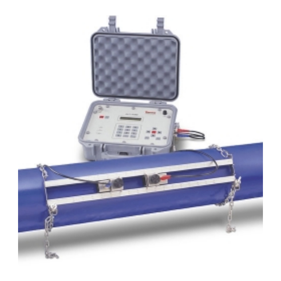
Its transducers can be mounted to a pipe within a matter of minutes, and flow measurements may be made without interrupting the flow or modifying pipe work. The DCT7088 can be configured using an integral keypad for entering variables such as pipe size, pipe material, wall thickness, and fluid type (refer to Section 3, page 8). -
Page 7: Transit Time Accuracy
..Theory of operation 1.2-B: F IGURE ROFILES Transit Time Accuracy Noninvasive ultrasonic measurements are subject to a variety of effects that can influence measurement accuracy. All ultrasonic instruments are velocity measuring devices and only infer volumetric flow from the operator-entered parameter of pipe inside diameter (ID). -
Page 8: Ordering
Ordering The table below describes ordering information for a standard DCT7088 flowmeter as well as available options. MODEL NUMBER Series: Digital Correlation Transit Time Flowmeters DCT7088 = DCT7088, RS232 digital interface with UltraScan signal analysis and configuration program Battery Duration... -
Page 9: Functional
..Specifications 1.5.2 Functional Outputs 4-20 mA (into 1000 ohms), 12-bit, isolated, loop- or self- powered; RS232 serial interface Power Supply Built-in lead acid gel battery providing 8 hours continuous operation Optional: 16 hours continuous operation Keypad 19-key with tactile action Display 40-character, 2-line, alphanumeric, backlit LCD Data Logger... -
Page 10: External Features
External Features Components Description Printer port: Provides output for optional external thermal printer. Connects to special cable which has 3-pin round connector on flowmeter end and DB9 connector on printer end. ON/OFF keys Battery Low light: Activates after approximately 7 or 14 hours of operation (depending on battery type). -
Page 11: Breakout Box Components
Breakout Box Components Components Description AC power cable DC power output cable DC power input connector: Connects DC power output cable to flowmeter. 4-20 mA output terminals Printer charger cable RS232 serial port Breakout box interface connector: Provides connections for DC power input from battery charger/AC adapter, for DC output cable for charging battery, for RS232... -
Page 12: Wiring The Current Loop
2. W IRING THE URRENT The 4-20 mA current loop module has an input terminal and an output terminal. Both are indicated on a label on the inside of the flowmeter door. The current loop output is rated for a loop resistance of up to 1 k ohms and is isolated for up to 5 kV when loop-powered. -
Page 13: Configuring & Operating The Flowmeter
3. C & O ONFIGURING PERATING THE LOWMETER The Keypad & Display The keypad provides access to the microprocessor for flowmeter configuration. During operation, the instrument’s 40-character LCD indicates flow rate and totalizer values. 3.1.1 Components Components Description Numeric keys: 0 through 9 and decimal (.). Arrow keys: For scrolling up, down, left, right. - Page 14 ..Direct menu access The address must be entered while the M is displayed (within approximately 4 seconds). If the M is no longer displayed, press MENU again followed by the 2-digit address. Menu Type Display Menu Menu Type Display Menu Primary Flow/Net Totalizer...
-
Page 15: Using The Arrow Keys To Access Menus
Using the Arrow Keys to Access Menus Another method of accessing the flowmeter’s menus is to use the LEFT or RIGHT ARROW keys to scroll through the menu structure. Menus are organized into 3 basic levels: 1) Main menu, 2) submenus, and 3) primary displays, setup menus, diagnostic menus. -
Page 16: Quick Setup Configuration
..Flowmeter configuration using setup menus To configure the flowmeter: 1. Access the setup menus individually by pressing MENU and entering the 2-digit address OR by scrolling through the submenus and selecting the desired setup menu. 2. a. If the setup menu requires a numeric entry, use the numeric keys to enter the value and press ENTER to accept the value. - Page 17 ..Quick setup configuration PIPE setup menu continued: 3.5-A ( ) & 3.5-B ( IGURES LEFT RIGHT b. Select the Pipe ID setup menu (12). Enter the pipe ID value, and press ENTER (Figure 3.5-C, below). c. Select the Pipe Material setup menu (13). Press the UP and DOWN ARROWS to scroll through the available options (Figure 3.5-D, below).
- Page 18 ..Quick setup configuration 5. Within the Transducer submenu: a. Access the Transducer Type setup menu (23). Currently, the only selection available is STANDARD, which MUST be selected for all applications using clamp-on transducers, including high temperature transducers (Figure 3.5-H, below). b.
-
Page 19: Primary Displays
Primary Displays The primary displays are for viewing only and cannot be configured. Primary displays include displayed values for flow rate, totalizers, velocity, signal strength, or low signal cutoff (menus 00 through 04). 3.6.1 Flow/Net Totalizer (00) The Flow/Net Totalizer (Figure 3.6-A, below) is the standard display used under normal operating condi- tions. -
Page 20: Additional Setup Menus Within The Pipe Submenu
Additional Setup Menus Within the PIPE Submenu *Not included in the Quick Setup configuration Following are setup menus not included in the Quick Setup configuration detailed in Section 3.5 (page 11). Setup menus are used primarily to enter configuration data or to view the flowmeter’s current configuration settings. -
Page 21: Additional Setup Menus Within The Fluid Submenu
..Additional setup menus within the LINER submenu 3.8-A ( ) & 3.8-B ( IGURES LEFT RIGHT Additional Setup Menus Within the FLUID Submenu *Not included in the Quick Setup configuration 1. Fluid Sound Speed setup menu (21): This menu can only be configured if you selected OTHER as the fluid type in Menu 20. - Page 22 ..Additional setup menus within the FLOW submenu 3.10-A 3.10-C ( IGURES THROUGH LEFT TO RIGHT TOP TO BOTTOM 3. Low Flow Cutoff setup menu (34): When a zero flow condition occurs (for example, as the result of a pump being shut off), internal sloshing, check valve leakage, and other fluid movement can prevent the flowmeter from reading total zero.
-
Page 23: Additional Setup Menus Within The Total Submenu
..Additional setup menus within the FLOW submenu 3.10-F ( ) & 3.10-G ( IGURES LEFT RIGHT 3.11 Additional Setup Menus Within the TOTAL Submenu *Not included in the Quick Setup configuration 1. Totalizer Units setup menu (36): The flow unit selected for the totalizer display may be different from the flow unit selected for the flow rate display (Figure 3.11-A, below). -
Page 24: Additional Setup Menus Within The Options Submenu
..Additional setup menus within the TOTAL submenu 3.11-E ( ) & 3.11-F ( IGURES LEFT RIGHT 3.12 Additional Setup Menus Within the OPTIONS Submenu *Not included in the Quick Setup configuration The OPTIONS submenu contains setup menus for several miscellaneous functions. 1. - Page 25 ..Additional setup menus within the OPTIONS submenu 3. RS232 Configuration setup menu (46): Use this menu to configure the RS232 port which allows the ® flowmeter to connect to an IBM -compatible PC using the UltraScan (refer to the UltraScan manual) or D-Link (refer to Appendix C, page 69) utilities (Figure 3.12-C, below).
- Page 26 ..Additional setup menus within the OPTIONS submenu 3.12-E 3.12-I ( IGURES THROUGH LEFT TO RIGHT TOP TO BOTTOM 5. Change Scale Factor Password setup menu (48): Use this menu to change the scale factor password which is designed to protect the scale factor from unauthorized or accidental changes. The flowmeter ships from the factory with the scale factor password disabled.
-
Page 27: Additional Setup Menus Within The Calibr Submenu
..Additional setup menus within the OPTIONS submenu 6. Unit ID (identification) Number setup menu (49): This number is determined by the operator to identify the specific instrument or site. Any whole number between 1 and 60,000 may be entered (Figure 3.12-N, below). -
Page 28: Zero Flow Set Method
..Additional setup menus within the CALIBR submenu Zero flow set method continued After the instrument is properly zeroed, it should display a stable reading well below 0.05 ft/s (0.015 m/s) under zero flow conditions with the low flow cutoff disabled. Prior to performing a zero set calibration, verify the following: 1. -
Page 29: Scale Factor Calibration
..Additional setup menus within the CALIBR submenu Manual zero set method continued 3.13-D ( ) & 3.13-E ( IGURES LEFT RIGHT 3.13.2 Scale Factor Calibration After setting and verifying the instrument’s zero point, you can set a scale factor to adjust the measured flow;... -
Page 30: Additional Setup Menus Within The 4-20 Ma Submenu
..Other CALIBR submenu options 2. Date and Time setup menu (54): Use this menu to set the date and time in the flowmeter’s internal clock. The time is expressed in military time (24-hour format), and the date is in the month-day-year format (Figure 3.13-I, below). - Page 31 ..Additional setup menus within the 4-20 mA submenu 4. Press ENTER. 5. Access Menu 58 again. 6. Press the DOWN ARROW to scroll to the 20 mA Calibrate screen (Figure 3.14-C, below). 7. Repeat step 3 for entering the 20 mA set point. 8.
-
Page 32: Additional Setup Menus Within The Alarms Submenu
3.15 Additional Setup Menus Within the ALARMS Submenu *Not included in the Quick Setup configuration The ALARMS submenu (70) contains the setup menus for programming and viewing the flowmeter’s alarm parameters. Up to 4 alarms may be independently programmed ON or OFF based on flow rate or signal strength values. -
Page 33: Viewing Alarms
..Additional setup menus within the ALARMS submenu Programming the alarm continued 9. Repeat steps 1-8 for each alarm you want to program. 3.15-B 3.15-F ( IGURES THROUGH LEFT TO RIGHT TOP TO BOTTOM 3.15.2 Viewing Alarms To view the ON/OFF status of the alarms: 1. - Page 34 ..Additional setup menus within the DATA LOG submenu The flowmeter stores completed datalog files and assigns a unique file number to each log. This allows data logs to be recorded and retrieved. Additionally, files can be viewed, deleted, or transferred in ASCII format to an IBM ®...
-
Page 35: Additional Setup Menus Within Diagnostics Submenu
..Additional setup menus within the DATA LOG submenu 2. Interval menu (81): Data log intervals must be entered in whole seconds, with a minimum interval of 1 second (Figure 3.16-F, below). 3.16-F IGURE 3. View menu: Use this menu to view which log files are stored in memory, the file sizes, and amount of log memory still available. -
Page 36: Additional Setup Menus Within Print Submenu
..Additional setup menus within the DIAGNOSTICS submenu 3. Reynolds Number/Profile Factor display (92): Displays the Reynolds number and flow profile factor currently being used by the flowmeter. The flow profile factor is calculated by the flowmeter and used to determine the effect of the flow profile on mean measured fluid velocity (Figure 3.17-C, below). 4. - Page 37 ..Additional setup menus within the PRINT submenu 1. Print Log Setup menu continued d. Enter the print interval in whole seconds, and press ENTER. Operation errors may occur if the log interval is too short to allow the selected data to be printed.
-
Page 38: Wiring & Installing The Transducers
4. W & I IRING NSTALLING THE RANSDUCERS Wiring The transducer terminals and cables are arranged in pairs and are labeled DN STREAM and UP STREAM. The downstream transducer cable has blue-banded ends; the upstream transducer has red-banded ends. IGURE Locate the symbol seen in Figure 4.1. - Page 39 ..Site selection & preparation 4.2-B IGURE Use the following guidelines when selecting the transducer site: a. Choose a section of pipe which is always full of liquid, such as a vertical pipe with up flow or a full horizontal pipe. b.
-
Page 40: Spacing & Mounting The Transducers
..Pipe selection & preparation Pipes with excessive corrosion or scaling create conditions which can make accurate measurement difficult or impossible; if possible, avoid selecting these sections of pipe as mounting locations. g. Remove any dirt, grease, rust, loose paint, or scale from the pipe surface prior to mounting the transducers. - Page 41 ..Spacing & mounting the transducers 6. Install the portable transducers: a. Position the slides according to the calculated spacing. The top rail of the rack is marked in inches and the bottom rail is marked in millimeters. b. Apply sonic coupling compound to a transducer face, and with the cable connector end of the transducer towards the outside of the rack, install the transducer beneath one of the slides.
-
Page 42: Transducer Mounting Methods
..Spacing & mounting the transducers 8. Continued a. Refer to Figure 1.6 (page 5) to locate the upstream and downstream connectors on the side of the meter. b. The upstream transducer cable has red-banded ends, and the downstream transducer cable has blue-banded ends (Figure 4.3-B, page 36). -
Page 43: W Method
..V method 4.4-A: V M IGURE OUNT 4.4.2 W Method In many instances, flowmeter performance on small metallic pipes with outer diameters of 4 inches (100 millimeters) or less can be improved by using the W mounting method (Figure 4.4-B, below). With the W method, the sound wave traverses the fluid 4 times and bounces off the pipe walls 3 times. -
Page 44: Z Method
4.4.3 Z Method The signal transmitted in a Z method installation has less attenuation than a signal transmitted with the V method. This is because the Z method utilizes a directly transmitted (rather than reflected) signal which transverses the liquid only once. The Z method (Figure 4.4-C, below) is used primarily in applications where the V method cannot work due to signal attenuation from excessive air or solids in the liquid, thick scale, poorly bonded linings, or very large pipes. - Page 45 ..Z method 4.4-D 4.4-I ( IGURES THROUGH LEFT TO RIGHT TOP TO BOTTOM 10. Draw a horizontal line along the pipe from the centerline of the 3 o’clock transducer position. Refer to Figure 4.4-J (below), and use a level to ensure that the line is level with the top of the pipe. The line should be at least 3 inches (76 millimeters) longer than the transducer spacing calculated by UltraScan.
- Page 46 ..Z method 12. Wrap the paper firmly back on the pipe. Have the point where the ends of the paper come together line up with the horizontal line on the 3 o’clock side of the pipe. Ensure that the inside corner of the straight edge of the paper is aligned with the mark made for the transducer spacing.
-
Page 47: Wv And Ww Methods
..Z method The figure below illustrates the final Z method installation. 4.4-P IGURE 4.4.4 WV and WW Methods For applications with pipe diameters smaller than 2 inches (50 millimeters), the WV and WW methods are options to achieve higher accuracy and stability when reasonable signal strength can be obtained (10% or higher). - Page 48 Other tape materials generally do not satisfy performance or safety specifications. Please contact Thermo when more tape strips are needed. 1. Wipe grease off the coupling surfaces of both transducers. Clean the surfaces with detergent and let dry (Figure 4.5-B, below).
- Page 49 ..Small pipe applications 4.5-D ( ) & 4.5-E ( IGURES LEFT RIGHT...
-
Page 50: Emergency Overrides & Master Erase
5. E & M MERGENCY VERRIDES ASTER RASE Since these 2 procedures allow critical data to be accessed and changed, this page may be re- moved from the instruction manual to prevent unauthorized use of these features. Emergency Overrides In the event that a user-entered password is forgotten, the following emergency override passwords may be used: 42 for the system password and 43 for the scale factor password. -
Page 51: Maintenance & Troubleshooting
6. M & T AINTENANCE ROUBLESHOOTING Replacing the Fuse Prevent possible electrical shock and/or damage to the meter – disconnect power to the meter PRIOR to wiring. 6.1.1 Flowmeter Fuse The fuse located on the front panel of the flowmeter (upper right corner) protects the instrument from overcurrent or short circuits from the internal battery. -
Page 52: Charging The Flowmeter
Charging the Flowmeter The DCT7088 is a DC-powered instrument that normally operates from the internal 12-V battery supplied with the unit. It may also be powered by one of the following sources which connect to the 12-15 Vdc input on the breakout box: •... -
Page 53: Troubleshooting & Support
6. If we determine the problem cannot be resolved over the phone, return the entire unit to the factory. 6.5.2 Local Representative Support The local Thermo representative is the first contact for support and is well equipped to answer questions and provide application assistance. Your representative has access to product information and current software revisions. -
Page 54: Upgrades
Thermo plant. A shop charge may apply for alignment and calibration services. Thermo shall be liable only to replace or repair, at its option, free of charge, products which are found by Thermo to be defective in material or workmanship, and which are reported to Thermo within the warranty period as provided above. -
Page 55: Appendix A: Pipe Schedules
A: P PPENDIX CHEDULES This appendix provides pipe schedules as a convenient reference for the following pipe materials: steel, stainless steel, and PVC (Table A-1); cast iron (Table A-2); ductile iron (Table A-3). The inside diameters (IDs) listed in the following tables are calculated from the outside diameter (OD) and minimum wall thicknesses as specified in applicable standards. -
Page 59: Appendix B: Fluid Properties
B: F PPENDIX LUID ROPERTIES B.1 Fluid Sound Velocities & Kinematic Viscosities This section provides a table of fluid sound speeds and kinematic viscosities. The information is based on material from the Cameron Hydraulic Data Book (17th ed., Ingersoll-Rand, 1988) and Table of Physical and Chemical Constants (13th ed., Longmans, 1966). - Page 60 LIQUID c(m/s) c(ft/s) Amyl acetate 29.2 1173 3847 n-Amyl alcohol 28.6 1224 4015 iso-Amyl ether 1153 3782 Aniline 1656 5432 4.37 Argon -183.0 816.7 -297 2679 Asphalt, blended RC-0, MC-0, SC-0 ....159 - 324 37.8 60 - 108 RC-1, MC-1, SC-1 ....37.8 518 - 1080 159 - 324...
- Page 61 LIQUID t? C c(m/s) t? ? F c(ft/s) Automotive crankcase oils SAE-5W ........-17.8 1295 max SAE-10W ........-17.8 1295 - 2590 SAE-20W ........-17.8 2590 - 10350 SAE-20........98.9 5.7 - 9.6 SAE-30........98.9 9.6 - 12.9 SAE-40........98.9 12.9 - 16.8 SAE-50........
- Page 62 LIQUID t? C c(m/s) t? F c(ft/s) Caesium 3172 Calcium chloride 5%.......... 18.3 1.156 25%........15.6 Carbolic acid (phenol) 18.3 11.83 Carbon tetrachloride CCI 0.612 37.8 0.53 Carbon disulphide CS 1149 3769 0.33 0.298 Carbon tetrachloride 3077 Castor oil 18.6 1500 4920 37.8...
- Page 63 LIQUID c(m/s) c(ft/s) Cotton seed oil 37.8 37.9 54.4 20.6 Crude Oil 48°API........15.6 54.4 40°API........15.6 54.4 35.6 API ......... 15.6 17.8 54.4 32.6 API ......... 15.6 23.2 54.4 Salt Creek ......15.6 54.4 Cyclohexane 1278 4192 Cyclohexanol 1622 5320 Decane-n -17.8...
- Page 64 LIQUID c(m/s) c(ft/s) Diphenyl 1271 4169 Diphenyl ether 1462 4795 Ethanol 1156 3792 Ethanol amide 1724 5655 Ether (diethyl) 3231 Ethyl acetate CH COOC 1133 3716 0.49 Ethyl alcohol 1161.8 3811 Ethyl bromide C 3057 0.27 Ethyl glycol 1606 5268 Ethyl iodide 2873 Ethylene bromide...
- Page 65 LIQUID c(m/s) c(ft/s) Freon -11.......... 0.21 21.1 -12.......... 21.1 0.27 -21.......... 21.1 1.45 Fuel Oils 1 ..........21.1 2.39 - 4.28 37.8 2.69 2 ..........21.1 3.0 - 7.4 37.8 2.11 - 4.28 3 ..........21.1 2.69 - 5.84 37.8 2.06 - 3.97 5A...........
- Page 66 LIQUID c(m/s) c(ft/s) n-Heptane -17.8 0.928 22.4 1150 3772 37.8 0.511 Heptene 1082 3549 Heptyne 1159 3802 Hexane 1203 3946 n-Hexane -17.8 0.683 21.2 1085 3559 37.8 0.401 Honey 37.8 73.6 Hydrogen -256 1187 -429 3893 Industrial lubricants Turbine oils 685........
- Page 67 LIQUID c(m/s) c(ft/s) Machine lubricants, cont Cutting oils #1........37.8 30 - 40 54.4 17 - 23 #2........37.8 40 - 46 54.4 23 - 26 Indium 2215 7265 Ink, printers 37.8 550 - 2200 54.4 238 - 660 Insulating oil 21.1 24.1 max 37.8...
- Page 68 LIQUID c(m/s) c(ft/s) Methylene chloride 23.5 1064 3490 Methylene iodide 977.7 3207 Milk 1.13 Molasses A, first........37.8 281 - 5070 54.4 151 - 1760 B, second....... 37.8 1410 - 13.2M 54.4 660 - 3.3M C, blackstrap......37.8 2630 - 55M 54.4 1320 - 16.5M Naphthalene...
- Page 69 LIQUID c(m/s) c(ft/s) Paraldehyde 1197 3926 Peanut oil 37.8 54.4 23.4 l-Pentadecene 1351 4431 Pentane 1008 3306 iso-Pentane 3231 n-Pentane -17.8 0.508 1044 3424 26.7 0.342 Petrolatum 54.4 20.5 71.1 Petroleum ether 15.6 31(est) Phenol 1274 4179 Potassium 1840 6035 n-Propanol 1220 4002...
- Page 70 LIQUID c(m/s) c(ft/s) Sodium 2500 8200 Sodium chloride (fused) 1991 1562 6530 5%.......... 1.097 25%........15.6 Sodium hydroxide (caustic soda) 20%........18.3 30%........18.3 10.0 Soya bean oil 37.8 35.4 54.4 19.64 Sperm oil 37.8 21 - 23 54.4 15.2 Sugar solutions Corn syrup 86.4 Brix ......
- Page 71 LIQUID c(m/s) c(ft/s) Sugar solutions, cont Sucrose 76 Brix ......21.1 2200 37.8 Sulphur 1332 4369 Sulphuric acid 14.6 100% ........95% ........14.5 60% ........Tar, coke oven 21.1 600 - 1760 37.8 141 - 308 Tar, gas house 21.1 3300 - 66M 37.8...
-
Page 72: Clean Water Sound Speed Versus Temperature
LIQUID c(m/s) c(ft/s) Trielhylene glycol 21.1 Triethylamine 1189 3900 Turpentine 1225 4018 37.8 86.6 - 95.2 54.4 39.9 - 44.3 l-Undecene 1275 4182 Varnish, spar 37.8 Water distilled........1482.9 4864 1.0038 fresh........15.6 1.13 54.4 0.55 sea ......... 1.15 Water (sea) 1507.4 4944 (surface, 3.5% salinity) -
Page 73: Relationship Between Specific Gravity, Viscosity, & Sound Velocity For Petroleum Products
B.3 Relationship Between Specific Gravity, Viscosity, & Sound Velocity for Petroleum Products The graph below depicts the approximate relationship between specific gravity, viscosity and sound velocities for aliphatic hydrocarbons (petroleum products). -
Page 74: Appendix C: Monitoring & Downloading Data Logs Using D-Link
ONITORING OWNLOADING SING D-Link is PC-based user interface software that can communicate with DCT6088 and DCT7088 flowmeters to monitor and download data log information. C.1 Installing D-Link Start the PolyCD and select D-Link in Communication Software. Follow the instructions to install D-Link. -
Page 75: Monitoring Data Logs
C.3 Monitoring Data Logs Once communications between the PC and the meter establish, the program opens as shown in Figure C.3-A (below). Click the arrow below Get Log, and select the log file you want to check. Click Get Log. The log information downloads and displays as seen in Figure C.3-B (page 71). -
Page 76: Saving & Loading Data Logs
..Monitoring data logs C.3-B: D IGURE ISPLAYED LOG C.4 Saving & Loading Data Logs To save the currently displayed data log to a file, go to File and select Save Log. The file can then be opened in data processing software such as Excel ®... - Page 77 ..Saving & loading data logs IGURE...
Need help?
Do you have a question about the DCT7088 and is the answer not in the manual?
Questions and answers