
Related Manuals for Thermo 48i


Summary of Contents for Thermo 48i
- Page 1 Model 48i Instruction Manual Gas Filter Correlation CO Analyzer Part number 101891-00 8Apr2005...
- Page 2 © 2005 Thermo Electron Corporation. All rights reserved. “Analyze. Detect. Measure. Control” is a trademark of Thermo Electron Corporation. All other product names and logos are the property of their respective owner. Specifications, terms and pricing are subject to change. Not all products are available in all countries. Please consult...
-
Page 3: Table Of Contents
Averaging Time..............3-18 Calibration Factors Menu ............. 3-19 CO Background Correction..........3-20 CO Span Coefficients ............3-21 Calibration Menu ..............3-22 Calibrate CO Background..........3-23 Calibrate CO Coefficient ........... 3-24 Zero/Span Check Menu............. 3-25 Thermo Electron Corporation Model 48i Instruction Manual... - Page 4 Concentration..............3-99 Service Menu ..............3-101 Single/Dual/Auto Select ........... 3-102 Pressure Calibration ............3-103 Flow Calibration .............. 3-106 Initial S/R Ratio............... 3-109 Multi-point Calibration ........... 3-110 Preamp Board Calibration..........3-113 Temperature Calibration..........3-114 Model 48i Instruction Manual Thermo Electron Corporation...
- Page 5 Cleaning the Optics ..............5-2 IR Source Replacement ............5-3 Fan Filter Inspection and Cleaning .........5-3 Leak Test and Pump Check Out..........5-4 External Leaks ..............5-4 Leaks Across the Optional Zero/Span and Sample Solenoid Valves............5-4 Pump Rebuilding..............5-5 Thermo Electron Corporation Model 48i Instruction Manual...
- Page 6 I/O Expansion Board (Optional) Replacement ..... 7-31 Digital Output Board Replacement........7-33 Motherboard Replacement............ 7-34 Measurement Interface Board Replacement ......7-35 Front Panel Board Replacement..........7-36 LCD Module Replacement ........... 7-37 Service Locations..............7-39 Model 48i Instruction Manual Thermo Electron Corporation...
- Page 7 Serial Ports ................. 8-11 RS-232 Connection ............8-12 RS-485 Connection ............8-13 Ethernet Connection............8-13 External Accessory Connector ..........8-13 Chapter 9 Optional Equipment ................9-1 Internal Zero/Span Assembly ..........9-1 Internal Zero Air Scrubber ............9-1 Thermo Electron Corporation Model 48i Instruction Manual...
- Page 8 Format Specifier for Binary Responses ....... B-41 Format Specifier for Front-Panel Layout ......B-41 Appendix C MODBUS Protocol ................C-1 Serial Communication Parameters ..........C-2 TCP Communication Parameters ...........C-2 Application Data Unit Definition ...........C-2 Function Codes...............C-3 MODBUS Commands Supported..........C-8 viii Model 48i Instruction Manual Thermo Electron Corporation...
- Page 9 • Chapter 9 “Optional Equipment” describes the optional equipment that can be used with this analyzer. • Appendix A “Warranty” provides a copy of the warranty statement. Thermo Electron Corporation Model 48i Instruction Manual...
- Page 10 The hazard or unsafe practice could result in minor to moderate personal injury if the warning is ignored. Equipment Damage The hazard or unsafe practice could result in property damage if the warning is ignored. Model 48i Instruction Manual Thermo Electron Corporation...
- Page 11 The service procedures in this manual are restricted to qualified service personnel only. The Model 48i is supplied with a three-wire grounding cord. Under no circumstances should this grounding system be defeated. CAUTION If the LCD panel breaks, do not to let the liquid crystal contact your skin or clothes.
- Page 12 Preface Thermo Electron Corporation Model 48i Instruction Manual...
-
Page 13: Introduction
Introduction Chapter 1 The Model 48i CO Analyzer measures CO concentration using Gas Filter Correlation (GFC). The Model 48i combines proven detection technology, easy to use menu-driven software, and advanced diagnostics to offer unsurpassed flexibility and reliability. The Model 48i has the following features: •... -
Page 14: Principle Of Operation
4.6 microns. Because infrared absorption is a non-linear measurement technique, it is necessary to transform the basic analyzer signal into a linear output. The Model 48i uses an internally stored calibration curve to accurately linearize the instrument output over any range up to a concentration of 10,000 ppm. -
Page 15: Specifications
Introduction Specifications Figure 1-1. Model 48i Flow Schematic Specifications Table 1-1. Model 48i Specifications Preset ranges 0-1, 2, 5, 10, 20, 50, 100, 200, 500, 1000, 2000, 5000, 10000 (ppm or mg/m Custom ranges 0-1 to 10000 (ppm or mg/m Zero roise 0.02 ppm RMS (30 second averaging time) - Page 16 C-Link, MODBUS, and streaming data (all user selectable) Ethernet connection RJ45 connector for 10Mbs Ethernet connection, static or dynamic TCP/IP addressing – In non condensing environments. Performance specifications based on operation with 20 30 °C range. 48i Instruction Manual Thermo Electron Corporation...
-
Page 17: Installation
Equipment Damage Do not attempt to lift the instrument by the cover or other external fittings. Unpacking and The Model 48i is shipped complete in one container. If there is obvious Inspection damage to the shipping container when you receive the instrument, notify the carrier immediately and hold for inspection. - Page 18 Units without Optional I/O Board Figure 2-1. Remove the Packing Material 4. Remove the three shipping screws (Figure 2-2). Shipping Screws (3) Figure 2-2. Remove the Shipping Screws 5. Check for possible damage during shipment. Model 48i Instruction Manual Thermo Electron Corporation...
-
Page 19: Setup Procedure
5. Plug the instrument into an outlet of the appropriate voltage and frequency. WARNING The Model 48i is supplied with a three-wire grounding cord. Under no circumstances should this grounding system be defeated. Thermo Electron Corporation Model 48i Instruction Manual... - Page 20 Installation Setup Procedure Figure 2-3. Model 48i Rear Panel Vent to Exhaust Line Instrument Bulkhead at Atmospheric Pressure Input Gas Line Figure 2-4. Atmospheric Dump Bypass Plumbing Model 48i Instruction Manual Thermo Electron Corporation...
-
Page 21: Startup
3. Set instrument parameters such as operating ranges and averaging times to appropriate settings. For more information about instrument parameters, see the “Operation” chapter. 4. Before beginning the actual monitoring, perform a multipoint calibration as described in the “Calibration” chapter. Thermo Electron Corporation Model 48i Instruction Manual... - Page 22 Installation Startup Model 48i Instruction Manual Thermo Electron Corporation...
-
Page 23: Operation
• “Service Menu” page 3-101 describes service related menu items. • “Password” page 3-121 describes how to enter/change a password, lock and unlock the analyzer. Thermo Electron Corporation Model 48i Instruction Manual... -
Page 24: Display
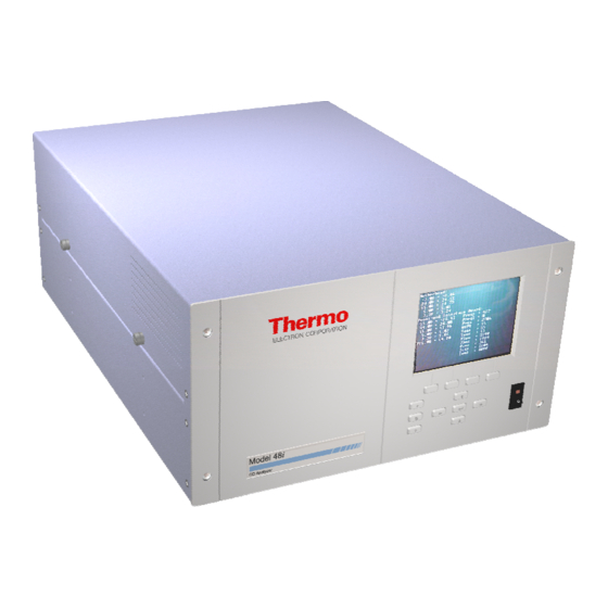
Figure 3-1. 48i Front Panel Display CAUTION If the LCD panel breaks, do not let the liquid crystal contact your skin or clothes. If the liquid crystal contacts your skin or clothes, wash it off immediately using soap and water. -
Page 25: Pushbuttons
) move the cursor up, down, left, and right or = Left, Right change values and states in specific screens. = Enter is used to select a menu item, accept/set/save a change, and/or toggle on/off functions. Thermo Electron Corporation Model 48i Instruction Manual... -
Page 26: Soft Keys
DIAGS ALARM Software Overview The Model 48i is based on menu-driven software as illustrated by the flowchart in Figure 3-3. The Power-Up screen, shown at the top of the flowchart, is displayed each time the instrument is turned on. This screen is displayed while the instrument is warming up and performing self-checks. -
Page 28: Power-Up Screen
Operation Software Overview Power-Up Screen The Power-Up screen is displayed on power up of the Model 48i. The Self-Test is displayed while internal components are warming up and diagnostic checks are performed. Run Screen The Run screen displays the CO concentrations. The status bar displays time and the status of the remote control interface, and optional zero/span solenoid valves, if installed. -
Page 29: Main Menu
Use select a submenu. XXLO WCONCENTRATIONXXLO 15.80 PPM SAMPLE 12:34 ALARMx MAIN MENU: >RANGE AVERAGING TIME CALIBRATION FACTORS CALIBRATION INSTRUMENT CONTROLS DIAGNOSTICS ALARMS RANGE DIAGS ALARM SERVICE PASSWORD Thermo Electron Corporation Model 48i Instruction Manual... -
Page 30: Range Menu
12:34 ALARMx RANGE: >GAS UNITS RANGE SET CUSTOM RANGES RANGE DIAGS ALARM XLOW RANGE CONCENTRATION 15.80 PPM SAMPLE 12:34 ALARMx RANGE: >GAS UNITS LO RANGE HI RANGE SET CUSTOM RANGES RANGE DIAGS ALARM Model 48i Instruction Manual Thermo Electron Corporation... -
Page 31: Single Range Mode
None None Ground 16, 18, 19, 35, 37 Signal Ground Note All channels are user definable. If any customization has been made to the analog output configuration, the default selections may not apply. Thermo Electron Corporation Model 48i Instruction Manual... -
Page 32: Dual Range Mode
Figure 3-5. See Table 3-3 for channels and pin connections. Dual range mode may be selected from the “Single/Dual/Auto Select” in the “Service Menu,” later in this chapter. Figure 3-5. Pin-Out of Rear Panel Connector in Dual Range Mode 3-10 Model 48i Instruction Manual Thermo Electron Corporation... -
Page 33: Autorange Mode
For example, the low CO range is set to 0–50 ppm and the high CO range is set to 0–10,000 ppm. Thermo Electron Corporation Model 48i Instruction Manual 3-11... - Page 34 Figure 3-7. Refer to Table 3-4 for channels and pin connections. Autorange mode may be selected from the “Single/Dual/Auto Select” in the “Service Menu”, later in this chapter. 3-12 Model 48i Instruction Manual Thermo Electron Corporation...
- Page 35 None Ground 16, 18, 19, 35, 37 Signal Ground Note All channels are user definable. If any customization has been made to the analog output configuration, the default selections may not apply. Thermo Electron Corporation Model 48i Instruction Manual 3-13...
-
Page 36: Gas Units
XXLO WCONCENTRATIONXXLO 15.80 PPM SAMPLE 12:34 ALARMx GAS UNITS: CURRENTLY: SET TO: MG/M3 ? AND SET RANGES AND CAL DEFAULT SETTINGXXXXXXXXXXX CHANGE VALUE SAVE RANGE DIAGS ALARM 3-14 Model 48i Instruction Manual Thermo Electron Corporation... -
Page 37: Co Range
Range menu or to return to the Press Run screen. XXLO WCONCENTRATIONXXLO 15.80 PPM SAMPLE 12:34 ALARMx RANGE: CURRENTLY: 10000 SET TO: 5000 ? CHANGE VALUE SAVE VALUE RANGE DIAGS ALARM Thermo Electron Corporation Model 48i Instruction Manual 3-15... - Page 38 Operation Range Menu Table 3-5. Standard Ranges mg/m 1,000 1,000 2,000 2,000 5,000 5,000 10,000 10,000 For more information about custom ranges, see “Set Custom Ranges” below. 3-16 Model 48i Instruction Manual Thermo Electron Corporation...
-
Page 39: Set Custom Ranges
1, 2, or 3. • to increment or decrement the numeric value. • Press to save the new range. • to return to the Set Custom Ranges menu or Press return to the Run screen. Thermo Electron Corporation Model 48i Instruction Manual 3-17... -
Page 40: Averaging Time
In the Main Menu, choose Averaging Time. • for a list of choices. • Press to save the averaging time. • Press to return to the Main Menu or to return to the Run screen. 3-18 Model 48i Instruction Manual Thermo Electron Corporation... -
Page 41: Calibration Factors Menu
In the Main Menu, choose Calibration Factors. • to move the cursor up and down. • to accept the choice. Press • Press to return to the Main Menu or to return to the Run screen. Thermo Electron Corporation Model 48i Instruction Manual 3-19... -
Page 42: Co Background Correction
CO background correction that is stored in memory and is being used to correct the CO reading. That is, the CO background correction is subtracted from the CO reading. 3-20 Model 48i Instruction Manual Thermo Electron Corporation... -
Page 43: Co Span Coefficients
CO Span Coefficients The CO span coefficient is usually calculated by the instrument processor during calibration. The span coefficients are used to correct the CO readings and normally has a value near 1.000. Thermo Electron Corporation Model 48i Instruction Manual 3-21... -
Page 44: Calibration Menu
The dual and autorange modes have two CO span factors (high and low). This allows each range to be calibrated separately. This is necessary if the 3-22 Model 48i Instruction Manual Thermo Electron Corporation... -
Page 45: Calibrate Co Background
The Calibrate CO Background screen is used to adjust the CO background, or perform a “zero calibration”. Before performing a zero calibration, ensure the analyzer samples zero air for at least 5 minutes. Thermo Electron Corporation Model 48i Instruction Manual 3-23... -
Page 46: Calibrate Co Coefficient
• pushbuttons to move the cursor left or right. • to increment or decrement the numeric value. • Press to calculate and save the new coefficient based on the entered span concentration. 3-24 Model 48i Instruction Manual Thermo Electron Corporation... -
Page 47: Zero/Span Check Menu
In the Main Menu, choose Calibration > Zero/Span Check. • to move the cursor up and down. • Press to accept the choice. • Press to return to the Calibration menu or to return to the Run screen. Thermo Electron Corporation Model 48i Instruction Manual 3-25... - Page 48 Run screen. XXLO WCONCENTRATIONXXLO 15.80 PPM SAMPLE 12:34 ALARMx NEXT DATE AND TIME: 19 MAR 2005 12:34 PRESS TO EDIT SETTING: DAYS SET MONTHS CHANGE VALUE SAVE VALUE RANGE DIAGS ALARM 3-26 Model 48i Instruction Manual Thermo Electron Corporation...
- Page 49 • In the Main Menu, choose Calibration > Zero/Span Check > Zero, Span or Purge Duration Min. • to increment and decrement the numeric value. • Press to save the duration value. Thermo Electron Corporation Model 48i Instruction Manual 3-27...
- Page 50 Zero/Span Check menu or return to the Run screen. XXLO WCONCENTRATIONXXLO 15.80 PPM SAMPLE 12:34 ALARMx ZERO/SPAN AVERAGING TIME: CURRENTLY: 30 SEC SET TO: 20 SEC ? CHANGE VALUE SAVE VALUE RANGE DIAGS ALARM 3-28 Model 48i Instruction Manual Thermo Electron Corporation...
-
Page 51: Instrument Controls Menu
In the Main Menu, choose Instrument Controls. • to move the cursor up and down. • Press to accept the choice. • Press to return to the Main Menu or to return to the Run screen. Thermo Electron Corporation Model 48i Instruction Manual 3-29... -
Page 52: Datalogging Settings
Run screen. XXLO WCONCENTRATIONXXLO 15.80 PPM SAMPLE 12:34 ALARMx DATALOGGING SETTINGS: >SELECT SREC/LREC SREC VIEW LOGGED DATA ERASE LOG SELECT CONTENT COMMIT CONTENT RESET TO DEFAULT CONTENT CONFIGURE DATA LOGGING RANGE DIAGS ALARM 3-30 Model 48i Instruction Manual Thermo Electron Corporation... - Page 53 In the Main Menu, choose Instrument Controls > Datalogging Settings > Select SREC or LREC > View Logged Data. • for a list of choices. • Press to set the filter type and continue to record selection menu. Thermo Electron Corporation Model 48i Instruction Manual 3-31...
- Page 54 Date/Time Filter The Date/Time Filter screen is used to view and change the system date and time. • to increment or decrement the selected date field. • to advance to next date field. 3-32 Model 48i Instruction Manual Thermo Electron Corporation...
- Page 55 RANGE DIAGS ALARM Erase Log The Erase Log is used to enter the Erasure Warning screen (read only). • In the Main Menu, choose Instrument Controls > Datalogging Settings > Erase Log. Thermo Electron Corporation Model 48i Instruction Manual 3-33...
- Page 56 > Select Content. • to move the cursor up and down. • Press to select a choice. • Press to return to the Datalogging Settings menu or return to the Run screen. 3-34 Model 48i Instruction Manual Thermo Electron Corporation...
- Page 57 Measurements, and Analog Inputs (if the I/O expansion board is installed). • In the Main Menu, choose Instrument Controls > Datalogging Settings > Select Content > Field 1-32. • to move the cursor up and down. • Press to select a choice. Thermo Electron Corporation Model 48i Instruction Manual 3-35...
- Page 58 • Press to return to the Choose Item Type submenu or return to the Run screen. XXLO WCONCENTRATIONXXLO 15.80 PPM SAMPLE 12:34 ALARMx CONCENTRATIONS: >NONE <-- RANGE STATUS RANGE DIAGS ALARM 3-36 Model 48i Instruction Manual Thermo Electron Corporation...
- Page 59 > Select Content > Select Field > Analog Inputs. • to move the cursor up and down. • Press to select a new choice. • Press to return to the Choose Item Type submenu or return to the Run screen. Thermo Electron Corporation Model 48i Instruction Manual 3-37...
- Page 60 Datalogging Settings menu or return to the Run screen. XXLO WCONCENTRATIONXXLO 15.80 PPM SAMPLE 12:34 ALARMx DATALOGGING SETTINGS: >LOGGING PERIOD MIN MEMORY ALLOCATION % DATA TREATMENT RANGE DIAGS ALARM 3-38 Model 48i Instruction Manual Thermo Electron Corporation...
- Page 61 • Press to set the percentage for both record types and proceed to the erasure warning screen. • Press to return to the Configure Datalogging menu or return to the Run screen. Thermo Electron Corporation Model 48i Instruction Manual 3-39...
- Page 62 Configure Datalogging menu or return to the Run screen. XXLO WCONCENTRATIONXXLO 15.80 PPM SAMPLE 12:34 ALARMx SET DATA TREATMENT: CURRENTLY: SET TO: CUR ? CHANGE VALUE SAVE RANGE DIAGS ALARM 3-40 Model 48i Instruction Manual Thermo Electron Corporation...
-
Page 63: Communication Settings
Settings > Baud Rate. • for a list of choices. • Press to save the new baud rate. • Press to return to the Communication Settings menu or to return to the Run screen. Thermo Electron Corporation Model 48i Instruction Manual 3-41... - Page 64 ID number if two or more of the same instrument are connected to one computer. Valid Instrument ID numbers are from 0 to 127. The Model 48i has a default Instrument ID of 48. For more information about the Instrument ID, see Appendix B “C-Link Protocol Commands”...
- Page 65 COMMUNICATION PROTOCOL: CURRENTLY: CLINK SET TO: STREAMING ? CHANGE VALUE SAVE VALUE RANGE DIAGS ALARM Streaming Data Configuration The Streaming Data Configuration is used to allow for configuration of the streaming data output. Thermo Electron Corporation Model 48i Instruction Manual 3-43...
- Page 66 The following interval times are available: 1, 2, 5, 10, 20, 30, 60, 90, 120, 180, 240, and 300 seconds. • In the Main Menu, choose Instrument Controls > Communication Settings > Streaming Data Config > Streaming Data Interval. 3-44 Model 48i Instruction Manual Thermo Electron Corporation...
- Page 67 Settings > Streaming Data Config > Item 1-18. • to move the cursor up and down. • Press to select a choice. • Press to return to the Streaming Data Config submenu or to return to the Run screen. Thermo Electron Corporation Model 48i Instruction Manual 3-45...
- Page 68 • Press to return to the Choose Item Signal submenu or return to the Run screen. XXLO WCONCENTRATIONXXLO 15.80 PPM SAMPLE 12:34 ALARMx CONCENTRATIONS: >NONE <-- RANGE STATUS RANGE DIAGS ALARM 3-46 Model 48i Instruction Manual Thermo Electron Corporation...
- Page 69 Settings > Streaming Data Config > Select Item > Analog Inputs. • to move the cursor up and down. • Press to select a new choice. • Press to return to the Choose Item Signal submenu or return to the Run screen. Thermo Electron Corporation Model 48i Instruction Manual 3-47...
- Page 70 RS-232 or RS-485. • to confirm and save the new selection change. • Press to return to the Communication Settings menu or to return to the Run screen. 3-48 Model 48i Instruction Manual Thermo Electron Corporation...
- Page 71 Settings > TCP/IP Settings. • to move the cursor up and down. • Press to select a choice. • Press to return to the Communication Settings menu or to return to the Run screen. Thermo Electron Corporation Model 48i Instruction Manual 3-49...
- Page 72 RANGE DIAGS ALARM IP Address The IP Address is used to edit the IP address. • In the Main Menu, choose Instrument Controls > Communication Settings > TCP/IP Settings > IP Address. 3-50 Model 48i Instruction Manual Thermo Electron Corporation...
- Page 73 • Press to save the new netmask. • Press to return to the TCP/IP Settings menu or to return to the Run screen. Thermo Electron Corporation Model 48i Instruction Manual 3-51...
- Page 74 MOVE CURSOR CHANGE VALUE SAVE RANGE DIAGS ALARM Host Name The host name screen is used to edit the host name. When DHCP is enabled, this name is reported to the DHCP server. 3-52 Model 48i Instruction Manual Thermo Electron Corporation...
-
Page 75: I/O Configuration
In the Main Menu, choose Instrument Controls > I/O Configuration. • to move the cursor up and down. • Press to select a choice. • Press to return to the Instrument Controls menu or return to the Run screen. Thermo Electron Corporation Model 48i Instruction Manual 3-53... - Page 76 Output Relay Settings > 1-10. • to move the cursor up and down. • Press to select a choice. • Press to return to the I/O Configuration menu or return to the Run screen. 3-54 Model 48i Instruction Manual Thermo Electron Corporation...
- Page 77 The Instrument State submenu allows the user to select the instrument state that is tied to the selected relay output. A submenu lists signal types of either alarm and non-alarm to choose from. Thermo Electron Corporation Model 48i Instruction Manual 3-55...
- Page 78 Output Relay Settings > Select Relay > Instrument State > Alarms. • for a list of choices. • Press to save the new selection for the relay. • Press to return to the Instrument State submenu or return to the Run screen. 3-56 Model 48i Instruction Manual Thermo Electron Corporation...
- Page 79 Output Relay Settings > Relay 1-10 > Instrument State > Non-Alarm. • for a list of choices. • Press to save the new selection for the relay. • Press to return to the Instrument State submenu or return to the Run screen. Thermo Electron Corporation Model 48i Instruction Manual 3-57...
- Page 80 Digital Input Settings > 1-16. • to move the cursor up and down. • Press to select a choice. • Press to return to the I/O Configuration menu or return to the Run screen. 3-58 Model 48i Instruction Manual Thermo Electron Corporation...
- Page 81 • Press to toggle and set the logic state open or closed. • Press to return to the Digital Input Settings menu or return to the Run screen. Thermo Electron Corporation Model 48i Instruction Manual 3-59...
- Page 82 CHOOSE ACTION: >NONE <-- CO MEASURE MODE ZERO GAS SPAN GAS INITIATE ZERO CHECK INITIATE SPAN CHECK SET BACKGROUND RANGE DIAGS ALARM AUTOCAL TO SPAN SET ANALOG OUT ZERO SET ANALOG OUT FS 3-60 Model 48i Instruction Manual Thermo Electron Corporation...
- Page 83 VOLTAGE CHANNEL 3 VOLTAGE CHANNEL 4 VOLTAGE CHANNEL 5 RANGE DIAGS ALARM VOLTAGE CHANNEL 6 CURRENT CHANNEL 1 CURRENT CHANNEL 2 CURRENT CHANNEL 3 CURRENT CHANNEL 4 CURRENT CHANNEL 5 CURRENT CHANNEL 6 Thermo Electron Corporation Model 48i Instruction Manual 3-61...
- Page 84 Analog Output Configuration menu or to return to the Run screen. XXLO WCONCENTRATIONXXLO 15.80 PPM SAMPLE 12:34 ALARMx SELECT OUTPUT RANGE: SELECTED OUTPUT: V ALL CURRENTLY: 0-10V SET TO: 0-5V CHANGE VALUE SAVE RANGE DIAGS ALARM 3-62 Model 48i Instruction Manual Thermo Electron Corporation...
- Page 85 Range Setting Range Status (NOx) Recommend not to change the setting for this output S/R Ratio LO S/R Ratio HI S/R Ratio Internal Temp User-set alarm min value User-set alarm max value Thermo Electron Corporation Model 48i Instruction Manual 3-63...
- Page 86 Analog Output Config menu or return to the Run screen. XXLO WCONCENTRATIONXXLO 15.80 PPM SAMPLE 12:34 ALARMx CHOOSE SIGNAL TYPE: CONCENTRATIONS OTHER MEASUREMENTS ANALOG INPUT RANGE DIAGS ALARM 3-64 Model 48i Instruction Manual Thermo Electron Corporation...
- Page 87 • Press to return to the I/O Configuration menu or return to the Run screen. Note The current outputs are only displayed if the I/O expansion board option is installed. Thermo Electron Corporation Model 48i Instruction Manual 3-65...
- Page 88 3 characters in length, and defaults to IN1to IN8 (user input channel number). • In the Main Menu, choose Instrument Controls > I/O Configuration > Analog Input Config > Select Channel > Descriptor. 3-66 Model 48i Instruction Manual Thermo Electron Corporation...
- Page 89 In the Main Menu, choose Instrument Controls > I/O Configuration > Analog Input Config > Select Channel > Units. • Press to save the new value. • Press to return to the Analog Input Config menu or return to the Run screen. Thermo Electron Corporation Model 48i Instruction Manual 3-67...
- Page 90 The Number of Table Points screen allows the user to select how many points are used in the conversion table. The points range from 2 to 10, with a default of 2. 3-68 Model 48i Instruction Manual Thermo Electron Corporation...
- Page 91 Analog Input Config > Table Point 1-10. • to move the cursor up and down. • Press to select a choice. • Press to return to the Analog Input Config menu or return to the Run screen. Thermo Electron Corporation Model 48i Instruction Manual 3-69...
- Page 92 Table Point submenu or to return to the Run screen. XXLO WCONCENTRATIONXXLO 15.80 PPM SAMPLE 12:34 ALARMx TABLE POINT 01 VOLTS: CURRENTLY: 5.00 SET TO: 8.00 ? INC/DEC SAVE VALUE RANGE DIAGS ALARM 3-70 Model 48i Instruction Manual Thermo Electron Corporation...
-
Page 93: Temperature Compensation
Model 48i does not require temperature compensation for EPA equivalency. When temperature compensation is on, the display shows the current internal instrument temperature (measured by a thermistor on the Interface board). -
Page 94: Pressure Compensation
This empirical data is used to compensate for any change in reaction chamber pressure. This compensation can be used even though the Model 48i does not require pressure compensation for EPA equivalency. When pressure compensation is on, the display represents the current pressure in the fluorescence chamber. -
Page 95: Screen Contrast
Instrument Controls menu or return to the Run screen. XXLO WCONCENTRATIONXXLO 15.80 PPM SAMPLE 12:34 ALARMx SCREEN CONTRAST: CURRENTLY: 50 % SET TO: 60 % ? CHANGE VALUE SAVE VALUE RANGE DIAGS ALARM Thermo Electron Corporation Model 48i Instruction Manual 3-73... -
Page 96: Service Mode
Model 48i. For more information about the service mode, see “Service Menu” later in this chapter. Note The service mode should be turned off when finished, as it prevents remote operation. -
Page 97: Diagnostics Menu
In the Main Menu, choose Instrument Controls > Diagnostics. • to move the cursor up and down. • Press to select a choice. • Press to return to the Instrument Controls menu or return to the Run screen. Thermo Electron Corporation Model 48i Instruction Manual 3-75... -
Page 98: Program Version
• Press to return to the Diagnostics menu or to return to the Run screen. XXLO WCONCENTRATIONXXLO 15.80 PPM SAMPLE 12:34 ALARMx PROGRAM VERSION: PRODUCT: MODEL 48i VERSION: 01.00.00 RANGE DIAGS ALARM 3-76 Model 48i Instruction Manual Thermo Electron Corporation... -
Page 99: Voltages
The Motherboard screen (read only) is used to display the current voltage readings on the motherboard. • In the Main Menu, choose Diagnostics > Voltages > Motherboard Voltages. • Press to return to the Voltages menu or to return to the Run screen. Thermo Electron Corporation Model 48i Instruction Manual 3-77... - Page 100 I/O Board Voltages The I/O Board screen (read only) is used to display the current voltage readings on the I/O expansion board. This menu is only accessible if the I/O expansion board is installed. 3-78 Model 48i Instruction Manual Thermo Electron Corporation...
-
Page 101: Temperatures
In the Main Menu, choose Diagnostics > Temperatures. • Press to return to the Diagnostics menu or to return to the Run screen. XXLO WCONCENTRATIONXXLO 15.80 PPM SAMPLE 12:34 ALARMx TEMPERATURES: >INTERNAL 34.6 BENCH 49.7 RANGE DIAGS ALARM Thermo Electron Corporation Model 48i Instruction Manual 3-79... -
Page 102: Pressure
In the Main Menu, choose Diagnostics > Flow. • Press to return to the Diagnostics menu or to return to the Run screen. XXLO WCONCENTRATIONXXLO 15.80 PPM SAMPLE 12:34 ALARMx FLOW: 1.108 LPM RANGE DIAGS ALARM 3-80 Model 48i Instruction Manual Thermo Electron Corporation... -
Page 103: Sample/Reference Ratio
The AGC Intensity screen (read only) displays the intensity (in Hertz) of the reference channel Automatic Gain Control (AGC) circuit. The AGC circuit optimizes the noise and resolution levels of the Model 48i. The AGC intensity reading should be about 250,000 Hertz. -
Page 104: Motor Speed
100.0 % RANGE DIAGS ALARM Analog Input Readings The Analog Input Readings screen (read only) displays the current user-scaled analog readings. • In the Main Menu, choose Diagnostics > Analog Input Readings. 3-82 Model 48i Instruction Manual Thermo Electron Corporation... -
Page 105: Analog Input Voltages
ANALOG IN 3 0.00 V ANALOG IN 4 0.00 V ANALOG IN 5 0.00 V ANALOG IN 6 0.00 V ANALOG IN 7 0.00 V RANGE DIAGS ALARM ANALOG IN 8 0.00 V Thermo Electron Corporation Model 48i Instruction Manual 3-83... -
Page 106: Digital Inputs
• In the Main Menu, choose Diagnostics > Relay States. • Press to return to the Diagnostics menu or to return to the Run screen. 3-84 Model 48i Instruction Manual Thermo Electron Corporation... -
Page 107: Test Analog Outputs
XXLO WCONCENTRATIONXXLO 15.80 PPM SAMPLE 12:34 ALARMx TEST ANALOG OUTPUTS: >ALL VOLTAGE CHANNEL 1 VOLTAGE CHANNEL 2 VOLTAGE CHANNEL 3 VOLTAGE CHANNEL 4 VOLTAGE CHANNEL 5 VOLTAGE CHANNEL 6 RANGE DIAGS ALARM Thermo Electron Corporation Model 48i Instruction Manual 3-85... -
Page 108: Instrument Configuration
In the Main Menu, choose Diagnostics > Instrument Configuration. • Press to toggle instrument configuration (in service mode only). • Press to return to the Diagnostics menu or to return to the Run screen. 3-86 Model 48i Instruction Manual Thermo Electron Corporation... -
Page 109: Contact Information
If the alarm is not a level alarm, the status will go from “OK” to “FAIL”. The number of alarms detected is displayed to indicate how many alarms have occurred. If no alarms are detected, the number zero is displayed. Thermo Electron Corporation Model 48i Instruction Manual 3-87... -
Page 110: Internal Temperature
8 to 47 °C. If the internal temperature reading goes beyond either the minimum or maximum alarm limit, an alarm is activated. The word “ALARM” appears in the Run screen and in the Main Menu. 3-88 Model 48i Instruction Manual Thermo Electron Corporation... - Page 111 • Press to save set to value as actual value. • Press to return to the Internal Temperatures menu or return to the Run screen. Thermo Electron Corporation Model 48i Instruction Manual 3-89...
-
Page 112: Bench Temperature
• Press to return to the Alarms menu or to return to the Run screen. XXLO WCONCENTRATIONXXLO 15.80 PPM SAMPLE 12:34 ALARMx BENCH TEMPERATURE: ACTUAL 48.4 >MIN 40.0 59.0 RANGE DIAGS ALARM 3-90 Model 48i Instruction Manual Thermo Electron Corporation... -
Page 113: Pressure
In the Main Menu, choose Alarms > Pressure. • Use the to move the cursor up and down. • Press to select a choice. • Press to return to the Alarms menu or to return to the Run screen. Thermo Electron Corporation Model 48i Instruction Manual 3-91... - Page 114 Pressure menu or to return to the Run screen. XXLO WCONCENTRATIONXXLO 15.80 PPM SAMPLE 12:34 ALARMx PRESSURE: ACTUAL MIN: 246.0 mmHg SET MIN TO: 500.0 mmHg? INC/DEC SAVE VALUE RANGE DIAGS ALARM 3-92 Model 48i Instruction Manual Thermo Electron Corporation...
-
Page 115: Sample Flow
• Press to save set value as actual vlaue. • Press to return to the Sample Flow menu or to return to the Run screen. Thermo Electron Corporation Model 48i Instruction Manual 3-93... -
Page 116: Bias Voltage
Alarms menu or to return to the Run screen. XXLO WCONCENTRATIONXXLO 15.80 PPM SAMPLE 12:34 ALARMx BIAS VOLTAGE: ACTUAL -110 V >MIN -130 V -100 V RANGE DIAGS ALARM 3-94 Model 48i Instruction Manual Thermo Electron Corporation... -
Page 117: Agc Instensity
In the Main Menu, choose Alarms > AGC Intensity. • to move the cursor up and down. • Press to select a choice. • Press to return to the Alarms menu or to return to the Run screen. Thermo Electron Corporation Model 48i Instruction Manual 3-95... - Page 118 AGC Intensity menu or to return to the Run screen. XXLO WCONCENTRATIONXXLO 15.80 PPM SAMPLE 12:34 ALARMx AGC INTENSITY: ACTUAL MIN: 150000 Hz SET MIN TO: 200000 Hz ? INC/DEC SAVE VALUE RANGE DIAGS ALARM 3-96 Model 48i Instruction Manual Thermo Electron Corporation...
-
Page 119: Motor Speed
Check. • Use the to move the cursor up and down. • Press to select a choice. • Press to return to the Alarms menu or to return to the Run screen. Thermo Electron Corporation Model 48i Instruction Manual 3-97... - Page 120 Zero or Span Check screen or return to the Run screen. XXLO WCONCENTRATIONXXLO 15.80 PPM SAMPLE 12:34 ALARMx MAX ZERO CHECK OFFSET: CURRENTLY: 0.200 SET TO: 0.500 ? CHANGE VALUE SAVE VALUE RANGE DIAGS ALARM 3-98 Model 48i Instruction Manual Thermo Electron Corporation...
-
Page 121: Zero And Span Auto Calibration
In the Main Menu, choose Alarms > Concentration. • to move the cursor up and down. • Press to select a choice. • Press to return to the Alarms menu or to return to the Run screen. Thermo Electron Corporation Model 48i Instruction Manual 3-99... - Page 122 Concentration menu or to return to the Run screen. XXLO WCONCENTRATIONXXLO 15.80 PPM SAMPLE 12:34 ALARMx CONCENTRATION: ACTUAL MIN: 10000 SET MIN TO: 0100.000 MOVE CURSOR INC/DEC SAVE VALUE RANGE DIAGS ALARM 3-100 Model 48i Instruction Manual Thermo Electron Corporation...
-
Page 123: Service Menu
In the Main Menu, choose Service. • to move the cursor up and down. • Press to select a choice. • Press to return to the Main Menu or to return to the Run screen. Thermo Electron Corporation Model 48i Instruction Manual 3-101... -
Page 124: Single/Dual/Auto Select
In the Main Menu, choose Service > Range Mode Select. • for a list of choices. • Press to save the new range mode. • to return to the Service menu or to return to the Press Run screen. 3-102 Model 48i Instruction Manual Thermo Electron Corporation... -
Page 125: Pressure Calibration
In the Main Menu, choose Service > Pressure Calibration. • Use the to move the cursor up and down. • Press to select a choice. • Press to return to the Service menu or to return to the Run screen. Thermo Electron Corporation Model 48i Instruction Manual 3-103... - Page 126 0.0 mmHg ? CONNECT VACUUM PUMP AND SAVE ZERO PRESSURE RANGE DIAGS ALARM Calibrate Pressure Span The Calibrate Pressure Span screen allows the user to view and set the pressure sensor calibration span point. 3-104 Model 48i Instruction Manual Thermo Electron Corporation...
- Page 127 • to overwrite pressure sensor calibration parameters with factory default values when pressed after • Press to return to the Pressure Calibration menu or return to the Run screen. Thermo Electron Corporation Model 48i Instruction Manual 3-105...
-
Page 128: Flow Calibration
In the Main Menu, choose Service > Flow Calibration. • Use the to move the cursor up and down. • Press to select a choice. • Press to return to the Service menu or to return to the Run screen. 3-106 Model 48i Instruction Manual Thermo Electron Corporation... - Page 129 0.000 LPM ? DISCONNECT PUMP AND SAVE ZERO PRESSURE RANGE DIAGS ALARM Calibrate Flow Span The Calibrate Flow Span screen allows the user to view and set the flow sensor calibrate span point. Thermo Electron Corporation Model 48i Instruction Manual 3-107...
- Page 130 • to overwrite pressure sensor calibration parameters with factory default values when pressed after • Press to return to the Flow Calibration menu or to return to the Run screen. 3-108 Model 48i Instruction Manual Thermo Electron Corporation...
-
Page 131: Initial S/R Ratio
Use the to move and change the value. • Press to save set to value as actual value. • Press to return to the Service menu or to return to the Run screen. Thermo Electron Corporation Model 48i Instruction Manual 3-109... -
Page 132: Multi-Point Calibration
In the Main Menu, choose Service > Multipoint Calibration. • Use the to move the cursor up and down. • Press to select a choice. • Press to return to the Service menu or to return to the Run screen. 3-110 Model 48i Instruction Manual Thermo Electron Corporation... - Page 133 RANGE: 10000 CAL FACTOR 1: 1.0000 CAL GAS 1: 0040.000 MOVE CURSOR CHANGE VALUE SAVE RANGE DIAGS ALARM Coefficients The Coefficients screen allows the user to view and recalculate the calibration coefficients. Thermo Electron Corporation Model 48i Instruction Manual 3-111...
- Page 134 In the Main Menu, choose Service > Multipoint Cal > Choose Cal Point > Coefficients. • Press to recalculate the coefficients. • Press to return to the Multipoint menu or to return to the Run screen. 3-112 Model 48i Instruction Manual Thermo Electron Corporation...
-
Page 135: Preamp Board Calibration
Service menu or to return to the Run screen. XXLO WCONCENTRATIONXXLO 15.80 PPM SAMPLE 12:34 ALARMx PREAMP BOARD CAL: SAMPLE: 127807 REFERENCE: 148256 SET TO: CHANGE VALUE SAVE VALUE RANGE DIAGS ALARM Thermo Electron Corporation Model 48i Instruction Manual 3-113... -
Page 136: Temperature Calibration
The analog output calibration is visible only when the instrument is in service mode. For more information on the service mode, see “Service Mode” earlier in the chapter. 3-114 Model 48i Instruction Manual Thermo Electron Corporation... - Page 137 VOLTAGE CHANNEL 3 VOLTAGE CHANNEL 4 VOLTAGE CHANNEL 5 VOLTAGE CHANNEL 6 CURRENT CHANNEL 1 RANGE DIAGS ALARM CURRENT CHANNEL 2 CURRENT CHANNEL 3 CURRENT CHANNEL 4 CURRENT CHANNEL 5 CURRENT CHANNEL 6 Thermo Electron Corporation Model 48i Instruction Manual 3-115...
- Page 138 Run screen. XXLO WCONCENTRATIONXXLO 15.80 PPM SAMPLE 12:34 ALARMX ANALOG OUTPUT CAL: ZERO CONNECT METER TO OUTPUT! SELECTED OUTPUT: SET TO: SAVE VALUE INC/DEC SET OUTPUT TO: 0.0 V RANGE DIAGS ALARM 3-116 Model 48i Instruction Manual Thermo Electron Corporation...
-
Page 139: Analog Input Calibration
The analog input calibration is visible only when the instrument is in service mode. For more information on the service mode, see “Service Mode” earlier in the chapter. Note This screen is present only when the I/O expansion board option is installed. Thermo Electron Corporation Model 48i Instruction Manual 3-117... - Page 140 INPUT CHANNEL 5 INPUT CHANNEL 6 INPUT CHANNEL 7 RANGE DIAGS ALARM INPUT CHANNEL 8 XXLO WCONCENTRATIONXXLO 15.80 PPM SAMPLE 12:34 ALARMx ANALOG INPUT CAL: >CALIBRATE ZERO CALIBRATE FULL SCALE RANGE DIAGS ALARM 3-118 Model 48i Instruction Manual Thermo Electron Corporation...
- Page 141 Use the to increment or decrement the numeric value. • Press to save the value. • Press to return to the Analog Input Calibration screen or to return to the Run screen. Thermo Electron Corporation Model 48i Instruction Manual 3-119...
-
Page 142: Display Pixel Test
Service menu or to return to the Run screen. XXLO WCONCENTRATIONXXLO 15.80 PPM SAMPLE 12:34 ALARMx DISPLAY PIXEL TEST: DURING TEST PRESS TO EXIT, TOGGLEXXXXXX BEGIN TEST GO BACK TO MENU RANGE DIAGS ALARM 3-120 Model 48i Instruction Manual Thermo Electron Corporation... -
Page 143: Restore User Defaults
In the Main Menu, choose Password. • to move the cursor up and down. • Press to select a choice. • Press to return to the Main Menu or to return to the Run screen. Thermo Electron Corporation Model 48i Instruction Manual 3-121... -
Page 144: Lock Instrument
DIAGS ALARM Change Password The Change Password is used to set or change the password used to unlock the instrument’s front panel. • In the Main Menu, choose Password > Change Password. 3-122 Model 48i Instruction Manual Thermo Electron Corporation... -
Page 145: Remove Password
Password Menu or to return to the Run screen. XXLO WCONCENTRATIONXXLO 15.80 PPM SAMPLE 12:34 ALARMx REMOVE PASSWORD: PRESSING ENTER WILL REMOVE CURRENT PASSWORD AND DISABLE LOCKING REMOVE PASSWORD RANGE DIAGS ALARM Thermo Electron Corporation Model 48i Instruction Manual 3-123... -
Page 146: Enter Password
• Press to return to the Password Menu or to return to the Run screen. XXLO WCONCENTRATIONXXLO 15.80 PPM SAMPLE 12:34 ALARMx ENTER PASSWORD: ENTER PASSWORD RANGE DIAGS ALARM 3-124 Model 48i Instruction Manual Thermo Electron Corporation... -
Page 147: Calibration
So cylinder zero air should be scrubbed of the residual CO prior to its use in the Model 48i as a dilution gas or a zero standard. Room air which has been scrubbed of CO can also be used as the zero air source. -
Page 148: Flow Meter(S) And Controller(S)
, CO , water vapor, or hydrocarbons, since the Model 48i does not respond to these molecules. If water vapor is not removed, it might be necessary to correct the flow measurement data when calculating the dilution ratio of the span CO reference. -
Page 149: Pressure Regulator For Co Standard Cylinder
Perform the service checks of the “Preventive Maintenance” chapter. Select the operating range and the averaging time of the Model 48i. Note The averaging time should be less than the zero duration and less than the span duration. -
Page 150: Zero Adjust
Zero Adjust Use the following procedure to set the CO reading to zero. 1. Allow sufficient time for the Model 48i to warm up and stabilize. 2. Adjust the dilution system of Figure 4-1 so that zero air alone is present in the manifold. -
Page 151: Span Adjust
CO reading to the CO calibration gas. recorder response (percent scale) = (([CO] x 100)/URL) + Z Where: URL = nominal upper range limit of the instrument operating range = instrument response to zero air, %scale Thermo Electron Corporation Model 48i Instruction Manual... -
Page 152: Additional Concentration Standards
In addition, an atmospheric dump bypass should be utilized to ensure that the zero air gas flow is being delivered at atmospheric pressure. Record the Model 48i's response in percent of scale as A . Compute the zero drift from the following equation:... -
Page 153: References
The instrument can also be calibrated using a dual three-point calibration. Calibration The calibration points are divided into a “low” range and a “high” range consisting of three points each • Cal Point 1 • Cal Point 2 • Cal Point 3 Thermo Electron Corporation Model 48i Instruction Manual... -
Page 154: Default Coefficients
= flow rate of CO standard corrected to 25 °C and 760 mm Hg, LPM = flow rate of dilution air corrected to 25 °C and 760 mm Hg, LPM 2. Allow the Model 48i to sample this CO concentration standard until a stable response is obtained. - Page 155 Press The instrument will perform a series of calculations and save the new parameters. Thermo Electron Corporation Model 48i Instruction Manual...
- Page 156 Service Mode menu. 15. Select Coefficients and press The instrument will automatically calculate the new coefficients and save the new parameters. 16. Repeat Steps 1 through 13 for Hi Multi-Point Cal. 4-10 Model 48i Instruction Manual Thermo Electron Corporation...
-
Page 157: Replacement Parts
See the “Servicing” chapter for a list of replacement parts and the associated replacement procedures. WARNING If the equipment is operated in a manner not specified by the manufacturer, the protection provided by the equipment may be impaired. Thermo Electron Corporation Model 48i Instruction Manual... -
Page 158: Preventive Maintenance
Dry by blowing clean dry air over the mirror. 5. Reassemble following the above procedure in reverse. It is not necessary to realign any mirror following cleaning. 6. Calibrate the instrument. See the “Calibration” chapter in this manual. Model 48i Instruction Manual Thermo Electron Corporation... -
Page 159: Ir Source Replacement
• After cleaning the optics, the IR light intensities remain below 100,000 It is not necessary to recalibrate the Model 48i after replacing the IR source since the Model 48i is a ratio instrument, and replacing the IR source does not affect the calibration. -
Page 160: Leak Test And Pump Check Out
Repeat for the valve associated with the zero line by plugging the zero inlet, press and follow the “External Leaks” procedure. If the pressure drops below 250 mm Hg, the valve associated with the zero line is functioning normally. Model 48i Instruction Manual Thermo Electron Corporation... -
Page 161: Pump Rebuilding
2. Loosen the fittings and remove both lines going to the pump. 3. Remove the four screws from the top plate, remove top plate, flapper valve, and the bottom plate. Top Plate Flapper Plate Bottom Plate Diaphragm Figure 5-2. Rebuilding the Pump Thermo Electron Corporation Model 48i Instruction Manual... - Page 162 Teflon® (white) side of the diaphragm is facing up and that the flapper valves cover the holes of the top and bottom plate. 6. Perform the “Leak Test and Pump Checkout” procedure described in this chapter. Model 48i Instruction Manual Thermo Electron Corporation...
-
Page 163: Chapter 6 Troubleshooting
The Technical Support Department at Thermo Electron can also be consulted in the event of problems. See “Service Locations” at the end of this chapter for contact information. In any correspondence with the factory, please note both the serial number and program number of the instrument. - Page 164 Clean cells and flow components. Leaky correlation wheel Replace with a known good wheel. Analog test ramp Faulty recorder Replace recorder. D/A calibration off Recalibrate the D/A with a DVM known to be in calibration. Model 48i Instruction Manual Thermo Electron Corporation...
- Page 165 Replace pre-amp board. Alarm - AGC intensity Pre-amp Gain not set properly Check Gain adjustment. Defective measurement interface Replace measurement board interface board. Alarm - Motor Speed Defective measurement interface Replace measurement board interface board. Thermo Electron Corporation Model 48i Instruction Manual...
- Page 166 Internal cables not connected Check that all internal cables Status properly are connected properly. Recycle AC power to Alarm - Interface Board is defective instrument. If still alarming, Status change board. Alarm - I/O Exp Status Model 48i Instruction Manual Thermo Electron Corporation...
- Page 167 F R O N T P A N E L P J 6 P O W E R S W TRANSFORMER 3 P in (9 0 VAC or 2 4 0 VAC OPTIONS) Figure 6-1. Board-Level Connection Diagram - Common Electronics Thermo Electron Corporation Model 48i Instruction Manual...
-
Page 168: Board-Level Connection Diagrams
B E N C H H E A T E R A N D T H E R M . 4 P in 3 P in P J 5 A C P U M P 3 P in Figure 6-2. Board-Level Connection Diagram - Measurement System Model 48i Instruction Manual Thermo Electron Corporation... -
Page 169: Connector Pin Descriptions
+RS485 to Interface Board -RS485 to Interface Board 10-BASE-T Ethernet Output (+) Ethernet Output (-) Ethernet Input (+) Ethernet Input (-) EXPANSION BD +24V +24V Ground Ground Ground +RS485 to Expansion Board -RS485 to Expansion Board Thermo Electron Corporation Model 48i Instruction Manual... - Page 170 Analog Voltage Output 1 Analog Voltage Output 3 Ground Analog Voltage Output 5 Ground Ground Power Fail Relay COM Power Fail Relay N.O. Contact Ground TTL Input 3 TTL Input 4 TTL Input 6 Model 48i Instruction Manual Thermo Electron Corporation...
- Page 171 24V IN +24V Ground DIGITAL I/O +24V +24V Ground Ground Ground SPI Reset SPI Input SPI Output SPI Board Select SPI Clock EXT. RS485 -RS485 to Rear Panel +RS485 to Rear Panel Ground Thermo Electron Corporation Model 48i Instruction Manual...
- Page 172 LD1 – LCD Signal LD6 – LCD Signal LD2 – LCD Signal LD7 – LCD Signal LD3 – LCD Signal LCD Bias Voltage Ground Ground LCD_ONOFF – LCD Signal Keypad Row 2 Input 6-10 Model 48i Instruction Manual Thermo Electron Corporation...
- Page 173 Serial Port 1 CTS (+RS485 IN) RS232/RS485:B P1:B Serial Port 2 RX (-RS485 IN) Serial Port 2 TX (-RS485 OUT) Ground Serial Port 2 RTS (+RS485 OUT) Serial Port 2 CTS (+RS485 IN) AC IN AC-HOT AC-NEUT Thermo Electron Corporation Model 48i Instruction Manual 6-11...
- Page 174 SPI – Data Out SPI - CLK SPI - CS +15V +18V for IR Source Ground -100V -100V Return PRES MJ10 Pressure Sensor Input Ground +15V -15V FLOW MJ11 Flow Sensor Input Ground 6-12 Model 48i Instruction Manual Thermo Electron Corporation...
- Page 175 Z/S SOL. +24V Zero/Span Solenoid Control SAMPLE SOL. +24V Sample Solenoid Control SPAN1 SOL. PJ10 +24V Converter Solenoid Control SPAN2 SOL. PJ11 +24V Span 2 Solenoid Control AC O2 AC-HOT AC-NEUT AC-Ground Thermo Electron Corporation Model 48i Instruction Manual 6-13...
- Page 176 Designator Description MOTHER Ground BOARD Ground LCLK – LCD Signal Ground Ground LLP – LCD Signal LFLM – LCD Signal LD4 – LCD Signal LD0 – LCD Signal LD5 – LCD Signal 6-14 Model 48i Instruction Manual Thermo Electron Corporation...
- Page 177 +24V +24V LCD DATA LFLM_5V – LCD Signal LLP_5V – LCD Signal LCLK_5V – LCD Signal LCD_ONOFF_5V – LCD Signal Ground LCD Bias Voltage LD0_5V – LCD Signal LD1_5V – LCD Signal Thermo Electron Corporation Model 48i Instruction Manual 6-15...
- Page 178 EXPANSION I/O Analog Voltage Input 1 Analog Voltage Input 2 Analog Voltage Input 3 Ground Analog Voltage Input 4 Analog Voltage Input 5 Analog Voltage Input 6 Ground Analog Voltage Input 7 6-16 Model 48i Instruction Manual Thermo Electron Corporation...
- Page 179 MOTHER BD +24V +24V Ground Ground Ground +RS485 to Motherboard -RS485 to Motherboard Table 6-7. Digital Output Board Connector Pin Descriptions Connector Reference Signal Label Designator Description MOTHER BD +24V +24V Ground Thermo Electron Corporation Model 48i Instruction Manual 6-17...
- Page 180 Solenoid Drive Output 7 Solenoid Drive Output 8 Relay 1 Contact b Relay 2 Contact b Relay 3 Contact b Relay 4 Contact b Relay 5 Contact b Relay 6 Contact b 6-18 Model 48i Instruction Manual Thermo Electron Corporation...
- Page 181 SPI – Data Out SPI - CLK SPI - CS +15V +18V for IR Source -100V -100V Return +18V for IR Source IR Source Return IR Detector Cooler + IR Detector Cooler - IR Detector Thermo Electron Corporation Model 48i Instruction Manual 6-19...
-
Page 182: Service Locations
Connector Signal Label Description IR Detector Service Locations For additional assistance, Thermo Electron has service available from exclusive distributors worldwide. Contact one of the phone numbers below for product support and technical information. 866-282-0430 508-520-0430 6-20 Model 48i Instruction Manual... -
Page 183: Servicing
Servicing Chapter 7 This chapter explains how to replace the Model 48i subassemblies. It assumes that a subassembly has been identified as defective and needs to be replaced. For fault location information refer to the “Preventive Maintenance” chapter and the “Troubleshooting” chapter in this manual. - Page 184 7-31 “Digital Output Board Replacement” page 7-33 “Motherboard Replacement” page 7-34 “Measurement Interface Board Replacement” page 7-35 “Front Panel Board Replacement” page 7-36 “LCD Module Replacement” page 7-37 “Service Locations” page 7-39 Model 48i Instruction Manual Thermo Electron Corporation...
-
Page 185: Safety Precautions
The firmware can be updated by the user in the field via the serial port or over the Ethernet. This includes both the main processor firmware and the firmware in all low-level processors. Refer to the i-Port manual for the firmware update procedure. Thermo Electron Corporation Model 48i Instruction Manual... -
Page 186: Replacement Parts List
Servicing Replacement Parts List Replacement Parts Table 7-1 lists the replacement parts for the Model 48i major subassemblies. List Refer to Figure 7-2 to identify the component location. Table 7-1. Model 48i Replacement Parts Part Number Description 100480-00 Front Panel Pushbutton Board... -
Page 187: Cable List
Terminal Block and Cable Kit (DB25) 101556-00 Terminal Block and Cable Kit (DB37) Cable List Table 7-2 describes the Model 48i cables. See the “Troubleshooting” chapter for associated connection diagrams and board connector pin descriptions. Table 7-2. Model 48i Cables Part Number... - Page 188 Flow Transducer IR Source Cover Detector Assy Optical Bench and Pre-Amp Thermistor I/O Expansion Board (Opt) Front Panel Digital Output Board Front Panel Board Power Supply Measurement Interface Board Motherboard Figure 7-2. Component Layout Model 48i Instruction Manual Thermo Electron Corporation...
-
Page 189: Lowering The Partition Panel
1. Turn instrument OFF and unplug the power cord. 2. If the instrument is mounted in a rack, remove it from the rack. 3. Remove the cover. Thermo Electron Corporation Model 48i Instruction Manual... -
Page 190: Fuse Replacement
250VAC, 3 Amp, SlowBlow (for 100VAC and 110VAC models) 250VAC, 1.25 Amp, SlowBlow (for 220-240VAC models) 1. Turn instrument OFF and unplug the power cord. 2. Remove fuse drawer, located on the AC power connector. Model 48i Instruction Manual Thermo Electron Corporation... -
Page 191: Fan Replacement
2. Remove the fan guard from the fan and remove the filter. 3. Pull the power connectors off the fan. 4. Remove the four fan mounting screws and remove the fan. 5. Install a new fan following the previous steps in reverse. Thermo Electron Corporation Model 48i Instruction Manual... -
Page 192: Ir Source Replacement
3. Loosen both clamp screws from the IR source mounting posts and remove IR source. 4. Install a new IR source by following the previous steps in reverse. Ensure that the IR source element is evenly spaced between the mounting posts. 7-10 Model 48i Instruction Manual Thermo Electron Corporation... -
Page 193: Filter Wheel Replacement
Filter Wheel Access Hole Figure 7-5. Replacing the IR Source Filter Wheel Use the following procedure to replace the filter wheel. Replacement Equipment Required: Filter wheel Allen wrenches, 5/32-inch and 5/64-inch Philips screwdriver Thermo Electron Corporation Model 48i Instruction Manual 7-11... - Page 194 6. After the filter wheel is installed, spin the wheel and observe that it runs true on the motor shaft. 7-12 Model 48i Instruction Manual Thermo Electron Corporation...
-
Page 195: Chopper Motor Replacement
Allen wrenches, 5/32-inch and 5/64-inch Flatblade screwdriver Equipment Damage Some internal components can be damaged by small amounts of static electricity. A properly grounded antistatic wrist strap must be worn while handling any internal component. Thermo Electron Corporation Model 48i Instruction Manual 7-13... -
Page 196: Optical Bench Replacement
2. Disconnect the chopper motor cable from the MOT DRV connector on the measurement interface board, and disconnect the detector cable from the PREAMP cable connector on the measurement interface board. 3. Disconnect the plumbing connections from the optical bench. 7-14 Model 48i Instruction Manual Thermo Electron Corporation... -
Page 197: Optical Switch Replacement
1. Turn instrument OFF, unplug the power cord, and remove the cover. 2. Remove the optical bench following the “Optical Bench Replacement” procedure in this chapter. Thermo Electron Corporation Model 48i Instruction Manual 7-15... -
Page 198: Bench Heater Assembly Replacement
Figure 7-8. Replacing the Optical Switch (Inverted View) Bench Heater Use the following procedure to replace the bench heater assembly Assembly (Figure 7-8). Replacement Equipment Required: Bench heater Heat conductive compound Flatblade screwdriver 7-16 Model 48i Instruction Manual Thermo Electron Corporation... -
Page 199: Detector/Preamplifier Assembly Replacement
3. Remove the two screws holding the preamplifier cover to the preamplifier assembly and remove the cover. Thermo Electron Corporation Model 48i Instruction Manual 7-17... -
Page 200: Pump Replacement
Equipment Damage Some internal components can be damaged by small amounts of static electricity. A properly grounded antistatic wrist strap must be worn while handling any internal component. 1. Turn instrument OFF, unplug the power cord, and remove the cover. 7-18 Model 48i Instruction Manual Thermo Electron Corporation... - Page 201 7. Perform a leak test as described in the “Preventive Maintenance” chapter. Pump Pump Bracket Captive Screws (4) Shock Mounts (4) Floor Plate Pump Mounting Screws (2) (Bottom) Figure 7-10. Replacing the Pump Thermo Electron Corporation Model 48i Instruction Manual 7-19...
-
Page 202: Pressure Transducer Replacement
4. Remove the two pressure transducer assembly retaining screws and remove the pressure transducer assembly (Figure 7-11). Retaining Screws (2) Figure 7-11. Replacing the Pressure Transducer 5. To install the pressure transducer assembly, follow the previous steps in reverse. 7-20 Model 48i Instruction Manual Thermo Electron Corporation... -
Page 203: Pressure Transducer Calibration
If the Service Mode is not displayed on the Main Menu, use the following procedure to display it. a. At the Main Menu, press to scroll to Instrument Controls > press > to scroll to Service Mode > and press Thermo Electron Corporation Model 48i Instruction Manual 7-21... - Page 204 9. Wait at least 10 seconds for the ambient reading to stabilize, use to enter the known barometric pressure, and press to save the pressure value. 10. Reconnect the instrument tubing to the pressure transducer. 11. Install the cover. 7-22 Model 48i Instruction Manual Thermo Electron Corporation...
-
Page 205: Flow Transducer Replacement
Figure 7-12. Replacing the Flow Transducer 5. Install the new flow transducer following the previous steps in reverse. 6. Calibrate the flow transducer. Refer to the “Flow Transducer Calibration” procedure that follows. Thermo Electron Corporation Model 48i Instruction Manual 7-23... -
Page 206: Flow Transducer Calibration
Press to toggle the Service Mode to ON. c. Press > to return to the Main Menu. d. Continue the procedure at Step 2 to access the Flow Sensor Cal screen. 7-24 Model 48i Instruction Manual Thermo Electron Corporation... -
Page 207: Capillary Cleaning Or Replacement
Capillary cleaning wire (smaller than 0.015-inch) Equipment Damage Some internal components can be damaged by small amounts of static electricity. A properly grounded antistatic wrist strap must be worn while handling any internal component. Thermo Electron Corporation Model 48i Instruction Manual 7-25... -
Page 208: Optional Zero/Span And Sample Solenoid Valve Replacement
A properly grounded antistatic wrist strap must be worn while handling any internal component. 1. Turn instrument OFF, unplug the power cord, and remove the cover. 2. Unplug the solenoid electrical connector from the measurement interface board. 7-26 Model 48i Instruction Manual Thermo Electron Corporation... -
Page 209: Analog Output Testing
1. Connect a meter to the channel to be tested. Figure 7-14 shows the analog output pins and Table 7-3 identifies the associated channels. Figure 7-14. Rear Panel Analog Voltage Output Pins Thermo Electron Corporation Model 48i Instruction Manual 7-27... - Page 210 Refer to the “Analog Output Adjustment” procedure that follows. 6. Press to set the output to zero. The Output Set To: field displays Zero. 7-28 Model 48i Instruction Manual Thermo Electron Corporation...
-
Page 211: Analog Output Adjustment
(Voltage Channel 1-6) corresponding to the rear panel terminal pin where the meter is connected, then press The Analog Output Cal: screen displays. 4. With the cursor at Calibrate Zero, press The Analog Output Cal: line displays Zero Thermo Electron Corporation Model 48i Instruction Manual 7-29... -
Page 212: Ambient Temperature Calibration
A properly grounded antistatic wrist strap must be worn while handling any internal component. 1. Remove the instrument cover. 2. Tape the thermistor (Figure 7-3) to a calibrated thermometer. 7-30 Model 48i Instruction Manual Thermo Electron Corporation... -
Page 213: I/O Expansion Board (Optional) Replacement
5. Install the cover. I/O Expansion Board Use the following procedure to replace the optional I/O expansion board (Optional) (Figure 7-15). Replacement Equipment Required: I/O expansion board Nut driver, 3/16-inch Thermo Electron Corporation Model 48i Instruction Manual 7-31... - Page 214 5. To install the I/O expansion board, follow previous steps in reverse. Motherboard Support Bracket Mounting Stud Motherboard Digital Output Board I/O Expansion Board (Opt) Figure 7-15. Replacing the I/O Expansion Board (Optional) 7-32 Model 48i Instruction Manual Thermo Electron Corporation...
-
Page 215: Digital Output Board Replacement
1. Turn instrument OFF, unplug the power cord, and remove the cover. 2. Remove the I/O expansion board (optional), if used. See the “I/O Expansion Board Replacement” procedure in this chapter. 3. Disconnect the digital output board ribbon cable from the motherboard. Thermo Electron Corporation Model 48i Instruction Manual 7-33... -
Page 216: Motherboard Replacement
Replacement” procedure in this chapter. 4. Unplug all connectors from the motherboard. Note connector locations to facilitate reconnection. 5. Using the nut driver, remove the six standoffs securing the board to the rear panel. 7-34 Model 48i Instruction Manual Thermo Electron Corporation... -
Page 217: Measurement Interface Board Replacement
2. Pop off the measurement interface board from the four mounting studs and remove the board. 3. To install the measurement interface board, follow the previous steps in reverse. 4. Re-install the measurement bench. Refer to “Removing the Measurement Bench” in this chapter. Thermo Electron Corporation Model 48i Instruction Manual 7-35... -
Page 218: Front Panel Board Replacement
3. Pop off the board from the two top mounting studs and remove the board by lifting it up and off the slotted bottom support. 4. Replace the front panel board by following previous steps in reverse. 7-36 Model 48i Instruction Manual Thermo Electron Corporation... -
Page 219: Lcd Module Replacement
CAUTION If the LCD panel breaks, do not to let the liquid crystal contact your skin or clothes. If the liquid crystal contacts your skin or clothes, wash it off immediately using soap and water. Thermo Electron Corporation Model 48i Instruction Manual 7-37... - Page 220 4. Loosen left-side retaining screw (viewed from front) and slide the LCD module out towards the right and rear of the instrument. 5. Replace the LCD module by following previous steps in reverse. 7-38 Model 48i Instruction Manual Thermo Electron Corporation...
-
Page 221: Service Locations
Servicing Service Locations Service Locations For additional assistance, Thermo Electron has service available from exclusive distributors worldwide. Contact one of the phone numbers below for product support and technical information. 866-282-0430 Toll Free 508-520-0430 International Thermo Electron Corporation Model 48i Instruction Manual... - Page 222 Servicing Service Locations 7-40 Model 48i Instruction Manual Thermo Electron Corporation...
- Page 223 • “Electronics” page 8-7 describes the system boards, assemblies, and connectors. • “I/O Components” page 8-10 describes the input and output communication functions and components. Thermo Electron Corporation Model 48i Instruction Manual...
-
Page 224: System Description
System Description Hardware Hardware Model 48i hardware components (Figure 8-1) include: • Optical bench • Band-pass filter • Bench heater board • Chopper motor • Optical pickup • Gas filter wheel • Infrared source • Pre-amplifier assembly with IR detector •... -
Page 225: Optical Bench
This assembly is used for maintaining the optical bench at a constant temperature. Chopper Motor The chopper motor spins the gas filter wheel and chopper disk at a uniform speed. Thermo Electron Corporation Model 48i Instruction Manual... -
Page 226: Optical Pickup
The pump draws the sample gas through the optical filter bench. Purge Flow Switch The purge flow switch monitors the flow of purge gas when the filter wheel purge gas option is installed. (optional) Model 48i Instruction Manual Thermo Electron Corporation... -
Page 227: Software
The front panel display, serial and Ethernet data ports, and analog outputs are the means of communicating the results of the above calculations. The front panel display presents the concentrations simultaneously. The display is updated every 1-10 seconds, depending on the averaging time. Thermo Electron Corporation Model 48i Instruction Manual... - Page 228 Negative concentrations can be represented as long as they are within -5% of full-scale. The zero and span values may be set by the user to any desired value. Model 48i Instruction Manual Thermo Electron Corporation...
-
Page 229: Electronics
I/O connector with Power Fail Relay, 16 Digital Inputs, and 6 Analog Voltage Outputs. Internal Connectors Internal connectors include: • Function key panel and Display • Measurement Interface Board Data • I/O Expansion Board Data • Digital Output Board Thermo Electron Corporation Model 48i Instruction Manual... -
Page 230: Measurement Interface Board
The pressure sensor assembly consists of a board containing an instrumentation amplifier and a pressure transducer with a gas input fitting. The pressure transducer output is produced by measuring the pressure difference between the sample gas pressure and ambient air pressure. Model 48i Instruction Manual Thermo Electron Corporation... -
Page 231: Bench Heater Board
This board also includes signal buffers for the graphics display control signals and a high voltage power supply for the graphics display backlight. Thermo Electron Corporation Model 48i Instruction Manual... -
Page 232: I/O Components
11 bits: • 0-20 mA • 4-20 mA The user can calibrate each analog output zero and span point through firmware. At least 5% of full-scale over and under range are also supported. 8-10 Model 48i Instruction Manual Thermo Electron Corporation... -
Page 233: Analog Voltage Inputs (Optional)
RS-232 or RS-485. The serial baud rate is user selectable in firmware for standard speeds from 1200 to 19,200 baud. The user can also set the data bits, parity, and stop bits. The following protocols are supported: Thermo Electron Corporation Model 48i Instruction Manual 8-11... -
Page 234: Rs-232 Connection
All responses are terminated with a carriage return (hex 0D) Refer to Table 8-1 for the DB9 connector pin configuration. Table 8-1. RS-232 DB Connector Pin Configurations DB9 Pin Function Ground 8-12 Model 48i Instruction Manual Thermo Electron Corporation... -
Page 235: Ethernet Connection
Any serial port protocols may be accessed over Ethernet in addition to the serial port. External Accessory The external accessory connector is not used in the Model 48i analyzer. Connector This port is used in other models to communicate with smart external devices that may be mounted hundreds of feet from the analyzer using an RS-485 electrical interface. - Page 236 System Description I/O Components 8-14 Model 48i Instruction Manual Thermo Electron Corporation...
-
Page 237: Internal Zero/Span Assembly
Optional Equipment Chapter 9 The Model 48i is available with the following options: • “Internal Zero/Span Assembly” page 9-1 • “Internal Zero Air Scrubber” page 9-1 • “Filter Wheel Purge” page 9-1 • “Teflon Particulate Filter” page 9-3 • “I/O Expansion Board Assembly”... -
Page 238: Filter Wheel Purge
(green) will deliver the required 140cc/min purge flow. Flows greater than this are not recommended due to unstable cooling effects on the IR source. Lower flows are acceptable as long as the purge housing is adequately purged for the application. Model 48i Instruction Manual Thermo Electron Corporation... -
Page 239: Teflon Particulate Filter
Teflon Particulate A 5-10 micron pore size, two-inch diameter Teflon® element is available for Filter the Model 48i. This filter should be installed just prior to the SAMPLE bulkhead. When using a filter, all calibrations and span checks must be performed through the filter. -
Page 240: Mounting Options
Mounted in an EIA-style rack, includes mounting slides, and front panel EIA-rack mounting handles. Retrofit rack Mounted in a Thermo non-EIA rack, includes mounting slides, and retrofit front panel rack-mounting handles. Figure 9-2. Rack Mount Option Assembly Model 48i Instruction Manual... - Page 244 Optional Equipment Mounting Options Model 48i Instruction Manual Thermo Electron Corporation...
-
Page 245: Appendix A Warranty
PERSON OR ENTITY OTHER THAN SELLER WITHOUT SELLER'S PRIOR WRITTEN APPROVAL, OR ANY USE OF REPLACEMENT PARTS NOT SUPPLIED BY SELLER, SHALL IMMEDIATELY VOID AND CANCEL ALL WARRANTIES WITH RESPECT TO THE AFFECTED PRODUCTS. Thermo Electron Corporation 48i Instruction Manual... - Page 246 EXPRESS OR IMPLIED, ORAL OR WRITTEN, WITH RESPECT TO THE PRODUCTS, INCLUDING WITHOUT LIMITATION ALL IMPLIED WARRANTIES OF MERCHANTABILITY OR FITNESS FOR ANY PARTICULAR PURPOSE. SELLER DOES NOT WARRANT THAT THE PRODUCTS ARE ERROR-FREE OR WILL ACCOMPLISH ANY PARTICULAR RESULT. 48i Instruction Manual Thermo Electron Corporation...
-
Page 247: Appendix B C-Link Protocol Commands
Appendix B This appendix provides a description of the C-Link protocol commands that can be used to remotely control a Model 48i analyzer using a host device such as a PC or a datalogger. C-Link protocol may be used over RS-232, RS-485, or Ethernet. -
Page 248: Instrument Identification Number
(ASCII) character. The command in the example below begins with the ASCII character code 171 decimal, which directs the command to the Model 48i, and is terminated by a carriage return “CR” (ASCII character code 13 decimal). <ASCII 176> T I M E <CR>... - Page 249 C-Link Protocol Commands Commands Table B-1 lists the 48i C-Link protocol commands. The interface will respond to the command strings outlined below. Table B-1. C-Link Protocol Commands Command Description Page addr dns Reports/sets dns address B-32 addr gw Reports/sets default gateway address...
- Page 250 Reports/sets current date B-30 default params Sets parameters to default values B-31 dhcp Reports/sets state of use of DHCP B-33 diag volt iob Reports diagnostic voltage level for I/O expansion board B-16 Model 48i Instruction Manual Thermo Electron Corporation...
- Page 251 Reports coefficients of the curve developed from hi multi-point B-23 calibration high range Reports/selects current CO high range B-27 high ratio Reports sample/reference ratio calculated using the high B-10 avering time high sp conc Reports/sets high span concentration B-24 Thermo Electron Corporation Model 48i Instruction Manual...
- Page 252 Outputs long records in the format specified in the command B-17 lrec Outputs long records B-17 lrec format Reports/sets output format for long records (ASCII or binary) B-18 lrec layout Reports current layout of lrec data B-19 Model 48i Instruction Manual Thermo Electron Corporation...
- Page 253 Reports current layout of short record data B-19 srec mem size Reports maximum number of short records B-19 srec per Reports/sets short record logging period B-19 stream per Reports/sets current set time interval for streaming data B-21 Thermo Electron Corporation Model 48i Instruction Manual...
-
Page 254: Measurements
Table B-2. The example below sets the low range averaging time to 120 seconds. Send: set low avg time 8 Receive: set low avg time 8 ok Table B-2. Averaging Times Selection Averaging Time (seconds) 1 seconds Model 48i Instruction Manual Thermo Electron Corporation... - Page 255 27.2 °C. The example below shows that temperature compensation is on and that the internal temperature is 27.2 °C. Send: internal temp Receive: internal temp 27.2 deg C motor Thermo Electron Corporation Model 48i Instruction Manual...
- Page 256 In the example below, the instrument is reporting that the AGC circuit is on, that the instrument is in the span gas mode, and that the CO high concentration alarm is activated. Send: flags Receive: flags 80038000 B-10 Model 48i Instruction Manual Thermo Electron Corporation...
-
Page 257: Alarms
The example below sets the agc intensity alarm maximum value to 20. Send: set alarm agc intensity max 20 Receive: set alarm agc intensity max 20 ok alarm bias voltage min alarm bias voltage max Thermo Electron Corporation Model 48i Instruction Manual B-11... - Page 258 The example below reports that the CO concentration minimum is 5.2 ppm. Send: alarm conc min Receive: alarm conc min 5.2 ppm set alarm conc min value set alarm conc max value B-12 Model 48i Instruction Manual Thermo Electron Corporation...
- Page 259 The example below sets the motor speed alarm maximum value to 20 minutes. Send: set alarm motor speed max 20 Receive: set alarm motor speed max 20 ok alarm pressure min Thermo Electron Corporation Model 48i Instruction Manual B-13...
- Page 260 The example below shows the CO concentration minimum alarm trigger to ceiling, according to Table B-3. Send: alarm trig conc Receive: alarm trig conc 1 set alarm trig conc value B-14 Model 48i Instruction Manual Thermo Electron Corporation...
-
Page 261: Diagnostics
15, negative 15, positive 5, positive 3.3, positive 18 IR, positive 18 MOT, and VBIAS. Each voltage value is separated by a space. Send: diag volt mib Receive: diag volt mib 24.1 14.9 -14.9 4.9 3.2 17.9 17.9 Thermo Electron Corporation Model 48i Instruction Manual B-15... -
Page 262: Datalogging
These commands report the list of current selections for long record logging data, short record logging data, streaming data output, or the scratch pad (sp) list. The example below shows the list for streaming data output. B-16 Model 48i Instruction Manual Thermo Electron Corporation... - Page 263 47.995 smpfl 0.000 pres 0.000 avgt1 10 avgt2 10 cobkg -0.000 cocoef 1.000 lococoef 1.000 corange 10000000.000 locorange 10000000.000 motor 100.000 lrec srec lrec xxxx yy srec xxxx yy lrec aa:bb oo-pp-qq yy srec aa:bb oo-pp-qq yy Thermo Electron Corporation Model 48i Instruction Manual B-17...
- Page 264 The example below shows the output format for long records is ASCII with text, according to Table B-4. Send: lrec format Receive: lrec format 01 set erec format format B-18 Model 48i Instruction Manual Thermo Electron Corporation...
- Page 265 2038 recs, 10 blocks lrec per srec per These commands report the long and short records logging period. The example below shows that the short record logging period is 5 minutes. Thermo Electron Corporation Model 48i Instruction Manual B-19...
- Page 266 Note Issuing these commands will clear all the logging data memory. All the existing records should be retrieved using appropriate commands, if required. Send: set malloc lrec 10 Receive: set malloc lrec 10 ok B-20 Model 48i Instruction Manual Thermo Electron Corporation...
- Page 267 “set copy sp to lrec”, “set copy sp to srec”, or “set copy sp to stream” commands. Send: set sp field 1 34 Receive: set sp field 1 34 ok stream per Thermo Electron Corporation Model 48i Instruction Manual B-21...
-
Page 268: Calibration
This command will auto-calibrate the CO background. The example below shows a successful auto-calibration of the CO background. Send: set cal co bkg Receive: set cal co bkg ok set cal co coef B-22 Model 48i Instruction Manual Thermo Electron Corporation... - Page 269 The “high coef 0”, high coef 1”, and high coef 2” commands report the coefficients of the curve developed from the Hi Multi-Point Calibration in dual or auto range mode. The “low coef 0”, low coef 1”, and low coef 2” Thermo Electron Corporation Model 48i Instruction Manual B-23...
- Page 270 Send: sp conc Receive: sp conc 1000 set sp conc value set high sp conc value set low sp conc value B-24 Model 48i Instruction Manual Thermo Electron Corporation...
-
Page 271: Keys/Display
It is sent as a type '5' binary c_link response with no checksum. The RLE encoding consists of a 0 followed by an 8-bit count of consecutive 0xFF bytes. The following 'c' code will expand the incoming data. Thermo Electron Corporation Model 48i Instruction Manual B-25... - Page 272 This command is meant for backward compatibility on the C series. Screen information is reported using the “iScreen” command above. Send: screen Receive: screen This is an I series Instrument. Screen Information not available B-26 Model 48i Instruction Manual Thermo Electron Corporation...
-
Page 273: Measurement Configuration
The example below sets the CO full-scale range to 50 ppm. Send: set range 5 Receive: set range 5 ok Table B-6. Standard Ranges mg/m Selection 1,000 1,000 2,000 2,000 5,000 5,000 10,000 10,000 custom range Thermo Electron Corporation Model 48i Instruction Manual B-27... - Page 274 This command sets the zero/span valves to the sample mode. The example below sets the instrument to sample mode, that is, the instrument is reading the sample gas. Send: set sample Receive: set sample ok B-28 Model 48i Instruction Manual Thermo Electron Corporation...
- Page 275 These commands turn the pressure compensation on or off. The example below turns pressure compensation off. Send: set pres comp off Receive: set pres comp off ok temp comp Thermo Electron Corporation Model 48i Instruction Manual B-29...
-
Page 276: Hardware Configuration
This command sets the screen’s level of contrast, according to Table B-7. The example below sets the contrast level to 50%. Send: set contrast 5 Receive: set contrast 5 ok Table B-7. Contrast Levels Level Contrast Level 100% date B-30 Model 48i Instruction Manual Thermo Electron Corporation... - Page 277 This command reports the current time (24-hour time). The example below reports that the internal time is 2:15:30 pm. Send: time Receive: time 14:15:30 set time hh:mm:ss hh = hours mm = minutes ss = seconds Thermo Electron Corporation Model 48i Instruction Manual B-31...
-
Page 278: Communications Configuration
This command sets the analyzer’s IP address, where address consists of four numbers ranging from 0-255 inclusive, separated by “.”. Send: set addr ip 192.168.1.200 Receive: set addr ip 192.168.1.200 ok B-32 Model 48i Instruction Manual Thermo Electron Corporation... - Page 279 This command reports the current state of use of DHCP on or off. DHCP is used to assign an IP address to the analyzer automatically. The example below shows that DHCP is on. Send: dhcp Receive: dhcp on set dhcp onoff Thermo Electron Corporation Model 48i Instruction Manual B-33...
- Page 280 This command reports the host name string. Send: host name Receive: host name analyzer01 set host name string This command sets the host name string, where string is 1-13 alphanumeric characters. B-34 Model 48i Instruction Manual Thermo Electron Corporation...
- Page 281 Send: set mode local Receive: set mode local ok program no This command reports the analyzer’s model information and program version number, which will be dependant on the current version. Thermo Electron Corporation Model 48i Instruction Manual B-35...
-
Page 282: I/O Configuration
C-Link Protocol Commands I/O Configuration Send: program no Receive: program no iSeries 48i 01.01.10.003 set layout ack This command disables the stale layout/layout change indicator (‘*’) that is attached to each response if the layout has changed. Send: set layout ack... - Page 283 This command assigns digital input channel (1-16) to activate the action indicated by index (1-35), when the input transitions to the designated state (high or low). Use “list din var” command to obtain the list of supported index values and corresponding actions. Thermo Electron Corporation Model 48i Instruction Manual B-37...
- Page 284 Voltage Output Not Assigned Not Assigned Not Assigned Current Output Low CO Low CO High/Low CO Current Output Low CO High CO Range Status Current Output Not Assigned Not Assigned Not Assigned B-38 Model 48i Instruction Manual Thermo Electron Corporation...
- Page 285 “closed,” if all the relays are set to same state, that is all open or all closed. The example below shows that the status when all the relays logic is set to normally “open”. Send: relay stat Receive: relay stat open Thermo Electron Corporation Model 48i Instruction Manual B-39...
-
Page 286: Record Layout Definition
(e.g., all of the floating point inputs will be displayed with an 'f' output specifier, and all of the integer inputs will be displayed with a 'd' specifier). B-40 Model 48i Instruction Manual Thermo Electron Corporation... -
Page 287: Format Specifier For Ascii Responses
Each line is composed of three major components: (1) a text field, (2) a value field, and (3) a button. None of these three components is required. The text field contains statically displayed text. Thermo Electron Corporation Model 48i Instruction Manual B-41... - Page 288 All alarm information is presumed to be two bits long (low and high). The bitfield extraction is performed on the integer part of the source. Typical alarm information would appear as '@6.4'. B-42 Model 48i Instruction Manual Thermo Electron Corporation...
- Page 289 This is not currently used. Examples Some examples ('\n' is the C syntax for an end-of-line character): Concentrations\n Thermo Electron Corporation Model 48i Instruction Manual B-43...
- Page 290 -> remote, etc.). The selection list shows that only the first two values, in this case, are to be shown to the user when the button is pressed. The 'T' button indicates full translation, input code to string, and user selection number to output string. B-44 Model 48i Instruction Manual Thermo Electron Corporation...
- Page 291 The background value is taken from the 7th element, and the precision specifier is taken from the 8th. If the asterisk were not present, it would indicate instead that 8 digits after the decimal point should be displayed. Thermo Electron Corporation Model 48i Instruction Manual B-45...
- Page 292 C-Link Protocol Commands Record Layout Definition B-46 Model 48i Instruction Manual Thermo Electron Corporation...
-
Page 293: Appendix C Modbus Protocol
This is achieved by using the supported MODBUS commands listed below. For details of the Model 48i MODBUS Protocol specification, see the following topics: •... -
Page 294: Serial Communication Parameters
0x0000 to 0xFFFF (Passed back in response) Protocol Identifier 2 Bytes 0x00 (MODBUS protocol) Length 2 Bytes 0x0000 to 0xFFFF (Number of following bytes) Unit Identifier 1 Byte 0x00 to 0xFF (Passed back in response) 48i Instruction Manual Thermo Electron Corporation... -
Page 295: Function Codes
These requests specify the starting address, i.e. the address of the first output specified, and the number of outputs. The outputs are addressed starting at zero. Therefore, outputs numbered 1–16 are addressed as 0–15. Thermo Electron Corporation 48i Instruction Manual... - Page 296 Here is an example of a request and response to read outputs 2–15: Request Field Name (Hex) Function 0x01 Starting Address Hi 0x00 Starting Address Lo 0x02 Quantity of Outputs Hi 0x00 Quantity of Outputs Lo 0x0D 48i Instruction Manual Thermo Electron Corporation...
- Page 297 Request Function code 1 Byte 0x03 or 0x04 Starting Address 2 Bytes 0x0000 to maximum allowed by instrument Quantity of Registers 2 Bytes 1 to maximum allowed by instrument Thermo Electron Corporation 48i Instruction Manual...
- Page 298 Register value Lo (13) 0x64 The contents of register 10 are shown as the two byte values of 0x02 0x2B. The contents of registers 11–13 are 0x00 0x00, 0x00 0x64 and 0x00 0x64, respectively. 48i Instruction Manual Thermo Electron Corporation...
- Page 299 03=Illegal Data, 04=Slave Device Failure Here is an example of a request to write Coil 5 ON: Request Field Name (Hex) Function Output Address Hi Output Address Lo Output Value Hi Output Value Lo Thermo Electron Corporation 48i Instruction Manual...
-
Page 300: Modbus Commands Supported
Output Address Lo Output Value Hi Output Value Lo MODBUS Commands The following Tables 1–3 lists the MODBUS commands supported for the Supported Model 48i. Table C-1. Read Registers for 48i Register Number Variable 40001&40002 40003&40004 LO CO 40005&40006 HI CO 40007&40008... - Page 301 MODBUS Protocol MODBUS Commands Supported Table C-1. Read Registers for 48i Register Number Variable 40045&40046 ANALOG IN 7 40047&40048 ANALOG IN 8 40049&40050 NOT USED 40051&40052 NOT USED 40053&40054 NOT USED Table C-2. Write Coils for 48i Coil Number Action Triggered...
- Page 302 MODBUS Protocol MODBUS Commands Supported Table C-3. Read Coils for 48i Coil Number Status INTENSITY ALARM MOTOR SPEED ALARM BIAS VOLTAGE ALARM MB STATUS ALARM INTERFACE BD STATUS ALARM I/O EXP BD STATUS ALARM CONC ALARM C-10 48i Instruction Manual...
Need help?
Do you have a question about the 48i and is the answer not in the manual?
Questions and answers