Barrett 4050 Transporter Operating Manual
Hide thumbs
Also See for 4050 Transporter:
- Networking manual (65 pages) ,
- Quick start manual (2 pages)
Table of Contents
Advertisement
Quick Links
Advertisement
Table of Contents

Subscribe to Our Youtube Channel
Related Manuals for Barrett 4050 Transporter


Summary of Contents for Barrett 4050 Transporter
- Page 1 BARRETT Operating Manual 4050 Transporter BCM405051/1 © Barrett Communications Head Office: Barrett Communications Pty Ltd 47 Discovery Drive, Bibra Lake, WA 6163 Australia Tel: +61 8 9434 1700 Fax: +61 8 9418 6757 Email: information@barrettcommunications.com.au www.barrettcommunications.com.au...
-
Page 3: Table Of Contents
Contents INTRODUCTION 1 ..................5 Overview ....................6 Rear Ports - Left ..................7 Rear Ports - Right ..................8 Inside the Case ..................9 OPERATION 2 ....................11 Internal Battery ..................11 Fitting the Battery ................11 External Battery ..................15 Mains Power ..................16 CHARGING 3 ....................17 Solar Panel Charging ................18 Setting the Charge Profile ..............18 Vehicle 12V Accessory Port Charging .............20 The ARK Battery Charger ..............20... -
Page 5: Introduction 1
INTRODUCTION The Barrett 4050 Transporter combines Barrett 4050 HF radio equipment into an easily transportable rugged Pelican 1560 case allowing the system to be field operational in minutes. There is no longer a need for time-consuming unpacking, connecting and organising that can be impractical in emergency situations. -
Page 6: Overview
Overview The rear ports of the 4050 Transporter have been designed for optimal connec- tor protection without compromising quick and easy access. To access the connectors, turn the lids anti-clockwise and remove. Reference Description Solar panel input (Barrett solar panel only P/N BCA209010) -
Page 7: Rear Ports - Left
Rear Ports - Left Reference Description Ethernet connection Mains AC power connection (includes AC fuse and on/off switch) DC In from vehicle DC accessory outlet (cig. lighter socket) Earth (ground) stud... -
Page 8: Rear Ports - Right
Rear Ports - Right Reference Description Antenna In ATU connector GPS Connector Remote Head connector (DB-15) Accessory connector (DB-25) -
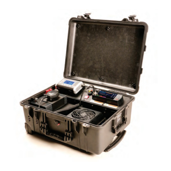
Page 9: Inside The Case
Inside the Case Reference Description ARK AC-DC Battery charger Solar and DC/DC charging switch Resettable circuit breaker (Battery isolator) 4050 transceiver control head 4050 hand microphone and clip DC Battery Internal/External connection for DC power 4050 transceiver body with fan unit Battery hold-down bracket... -
Page 11: Operation 2
• External Battery • Mains power This chapter outlines the set-up and powering of the Barrett 4050 Transporter. Internal Battery Fitting the Battery It may be necessary to install or change the internal battery to be suitable for specific circumstances. It is recommended to do this before any emergency situations take place to provide quick and efficient mobilisation when they do occur. - Page 12 Remove the seven cap-head Allen screws from the top of the display panel with an no. 2 (metric) Allen key. Connect positive and negative battery leads to the appropriate terminals and slide the battery into position. Ensure the battery is sitting beneath the L-shaped brackets on the left-hand side of the case and the battery cable is loosely under the brackets.
- Page 13 Lift the display panel enough to hold the securing bracket (below left) so that the set-screws from the previous step line up with the threaded inserts. Loosely secure the set-screws into the securing bracket. Push the battery hold-down bracket (and battery) tight against the left-hand side of the case.
- Page 14 Plug in the Anderson connec- tor. 10. Reconnect the VGA cable to the front of the transceiver and lock transceiver body back into the mounting plate. 11. Replace rear cables and engage the circuit breaker. Internal DC battery power is now available to the transceiver. When circuit breaker is engaged, power will automatically be supplied to the transceiver i.e.
-
Page 15: External Battery
External Battery To power the 4050 Transporter by external battery follow the below procedure: Disengage the circuit breaker Disconnect the internal battery by reversing step 9 of the previous section. Connect the red and black fittings to the appropriate terminals on the external battery. -
Page 16: Mains Power
Mains Power To power the 4050 Transporter by mains power, follow the below procedure: Connect the power plug to the socket in the left rear port of the case. Flip the switch next to the connection Power on the 4050 transceiver. -
Page 17: Charging 3
CHARGING The internal battery can be charged by multiple means: • Solar panels via onboard solar charge regulator • DC vehicle power (via the vehicle’s 12V Accessory port/cigarette lighter) via AC-DC Battery charger • AC Mains Power via AC-DC Battery charger The external battery can be charged as per the above however, it is important to note that the correct profiles and parameters must be set for the specific battery being used. -
Page 18: Solar Panel Charging
Solar Panel Charging The 4050 Transporter has an inbuilt solar charge regulator (a Victron SmartSolar Charge Controller MPPT100/15). It is installed inside the control panel enclosure and can be operated via bluetooth connectivity. Setting the Charge Profile It is very important to set the correct charge profile for on the charge con- troller for the type of battery installed. - Page 19 Ensure that the Barrett solar panels are placed in full sun. Connect solar panel cable to the solar charger port on the rear of the case as shown above. Flip the red internal switch to Solar Charging...
-
Page 20: Vehicle 12V Accessory Port Charging
Vehicle 12V Accessory Port Charging The ARK Battery Charger Reference Description LCD Screen Power and info button OK button Down button Up button... -
Page 21: Dc-Dc Charging
DC-DC Charging Connect the cable between the above indicated port on the rear of the 4050 Transporter and the vehicle accessory port (cigarette lighter). Flip the red internal switch to DC/DC Charging. Press to power on the charger. To turn the charger off, press and hold for 4 seconds. -
Page 22: Selecting Battery Profile
Not doing so may result in damage to the battery. It is recommended to check the set charge profile regardless of whether the 4050 Transporter has been supplied with or without an internal battery. Welcome Screen - This screen appears every time the charger is powered on. -
Page 23: Charge Screen
Charge Screen Battery Voltage Cycle Number of hours until full charge % capacity of battery Quick reference battery charge icon Further Information Alarm Messages Over Temperature - Charger or battery has exceeded safe temperature limit and will automatically adjust charge rate until charger or battery cools. Reverse Polarity - Battery is wrongly connected in reverse polarity (check 10A mini fuse on underside of charger). - Page 24 Note: During charge cycle, if battery did not reach 14.1 -14.9V (depending on battery type selected) after 25 hours the display will read; “Alarm check bat- tery”. The Ark Battery Charger will then proceed to float cycle. Testing Cycle - During the charge process the charger will pause every 15 mins for about 2 mins to let the battery voltage drop and measure the no-load capac- ity.
-
Page 25: Mains Power Charging
Mains Power Charging Connect AC mains power to rear of 4050 Transporter as indicated above (when connected to mains power, the AC-DC power supply sends 12V DC power to the AC-DC charger). Turn on battery charger and follow the steps to set charge profile on page... -
Page 27: Warranty Statement
Barrett Communications (hereafter referred to as ‘Seller’) provides a three (3) year warranty on all Barrett products from the date of shipment from the Seller. A one (1) year warranty from the date of shipment from the Seller is provided for all batteries. -
Page 28: Contact Details
Our customer / dealer technical support department can be contacted via land mail, email, telephone or via support ticket on the technical support web page. https://www.barrettcommunications.com.au/support/ Barrett Communications Pty Ltd Head Office: PO Box 1214, Bibra Lake WA 6965 AUSTRALIA Toll Free Tel: 1800 999 580 (Within Australia) - Page 29 Head Office: Barrett Communications Pty Ltd 47 Discovery Drive, Bibra Lake, WA 6163 Australia Tel: +61 8 9434 1700 Fax: +61 8 9418 6757 Email: info@barrettcommunications.com.au www.barrettcommunications.com.au Europe: Barrett Communications - Europe Unit 9, Fulcrum 2, Solent Way, Whiteley, Hampshire, PO15 7FN United Kingdom Tel: +44 (0) 1489 880 332 Fax: +44 (0) 1489 565 422 Email: uksales@barrettcommunications.co.uk...
Need help?
Do you have a question about the 4050 Transporter and is the answer not in the manual?
Questions and answers