Barrett 4050 HF SDR Operating And Installation Manual
Hide thumbs
Also See for 4050 HF SDR:
- Operating and installation manual (219 pages) ,
- Operating manual (34 pages) ,
- Installation manual (4 pages)
Table of Contents
Advertisement
Quick Links
Operating and Installation
Manual
Barrett 4050 HF SDR Transceiver
BCM40500/10
s/w v1.6.2
© Barrett Communications
Head Office:
Barrett Communications Pty Ltd
47 Discovery Drive, Bibra Lake, WA 6163 Australia
Tel: +61 8 9434 1700 Fax: +61 8 9418 6757
Email: information@barrettcommunications.com.au
www.barrettcommunications.com.au
Advertisement
Table of Contents

Related Manuals for Barrett 4050 HF SDR


Summary of Contents for Barrett 4050 HF SDR
- Page 1 Operating and Installation Manual Barrett 4050 HF SDR Transceiver BCM40500/10 s/w v1.6.2 © Barrett Communications Head Office: Barrett Communications Pty Ltd 47 Discovery Drive, Bibra Lake, WA 6163 Australia Tel: +61 8 9434 1700 Fax: +61 8 9418 6757 Email: information@barrettcommunications.com.au...
- Page 3 • EN60950-1:2002. FCC RF Exposure Compliance Statement The Barrett 4000 Series transceivers have been evaluated and comply with the Federal Communications Commission (FCC) RF exposure limits for the General Population/Uncontrolled exposure environment. In addition, the transceivers comply with the following standards and guide- lines: •...
- Page 4 RF Exposure Warning To ensure optimal transceiver performance and to avoid exposure to excessive electromagnetic fields, the antenna system must be installed according to the instructions provided. High voltages exist on the antenna during transmission and tuning. Do not touch the antenna during these activities. RF burns may result. Install the grounding system or counterpoise as directed to prevent RF burns from any metal part of the transceiver.
- Page 5 Antenna type Gain Minimum safe sepa- Typical (dBi) ration distance (m) Environ- ment Magnetic Loop Vehicle Multi-Wire Broadband Fixed Log-Period Fixed The above antennas are identified for reference only. It is important that the installer and operator maintain a minimum safe separation distance with the actual antenna used in the installation and to insure, in a vehicular environ- ment, that the transmitter is only used when persons outside the vehicle are at least the recommended lateral distance away.
-
Page 7: Table Of Contents
Contents INTRODUCTION 1 ................1 Introduction ....................2 Important Disclosure ................3 Terms & Abbreviations ................4 The Barrett 4050 HF Transceiver ..............6 Transceiver Front .................. 6 Transceiver Rear ..................7 Starting the Transceiver .................8 Keypad ......................8 Display ......................9 Swipe Menu ..................10 BASIC OPERATION 2 ................13... - Page 8 Beacon Call ..................30 Selcall ....................31 Telcall ....................32 Advanced Call History ................. 35 Advanced Selcall Functions .................39 Selcall Settings ..................39 Pagecall ....................40 GPS Request ..................41 GPS Position ..................43 Status Call ................... 44 Secure Call ..................45 Hangup Call ..................
- Page 9 Programming Via USB .................61 ADVANCED OPERATION 6 ..............63 ARINC Call ....................64 Audio - Advanced ..................65 Rx Configuration ................. 65 Tx Configuration ................. 65 Audio Bandwidth ................65 Line Audio ................... 66 Line Follows Digital Voice ..............66 Line Out Level ..................66 Line In Level ..................
- Page 10 Antenna 2 ................... 72 Modes ......................73 Mute (Squelch) ....................74 Network ......................76 Noise Reduction (NR) ..................78 RF Settings ....................79 Rx Preamp ................... 79 Tx Over Beep ..................79 Transmit Timeout ................80 Noise Blanker ..................80 Tx Power Level ..................80 AGC Hang ...................
- Page 11 Remote Access Password ..............87 SDV Programming Mode ..............87 Enable Power On PIN ................87 Tuning ......................88 INSTALLATION 7 .................89 Introduction ....................90 Installing a Secondary Control Head ............91 Installing Dual Antennas ................92 Mobile Installations ..................93 Mobile Pack ..................93 2019 Automatic Tuning Mobile HF Antenna ........
- Page 12 Power Connector ................142 GPS Connector .................. 142 Aux Control Head / BoB Connector ........... 143 Auxiliary Connector ................143 ATU Connector .................. 145 Microphone Connector ..............145 Control Head Rear Panel Connector ..........146 Cooling Fan Connector..............146 Appendix 3 - Overview of HF Operation ............147 HF Propagation .................
-
Page 13: Introduction 1
INTRODUCTION This chapter contains the following sections: • Introduction • The Barrett 4050 HF Transceiver • Activating the Transceiver • Display... -
Page 14: Introduction
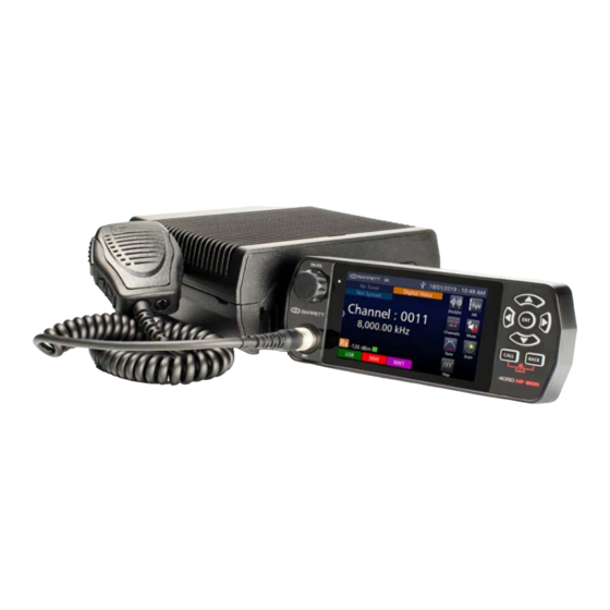
BARRETT 4050 HF SDR TRANSCEIVER - INTRODUCTION Introduction The Barrett 4050 Transceiver is an SDR based HF SSB transceiver with a fre- quency range of 1.6 to 30 MHz in transmit and 250kHz -30MHz. The Barrett 4050 is designed using the latest technology enabling a physically small pack- age with a full feature complement. -
Page 15: Important Disclosure
Box or WiFi adapter for IP connectivity and networking. Important Disclosure Please note that this manual describes all the features of the 4050 HF SDR Transceiver and that some variants of the 4050 may not have all the features installed. Illustrations may show accessories, optional equipment or other features which are not part of the standard specifica- tion and are not available in individual countries. -
Page 16: Terms & Abbreviations
BARRETT 4050 HF SDR TRANSCEIVER - INTRODUCTION Terms & Abbreviations Term / Definition Abbreviation Automatic Link Establishment Amplitude Modulation ARINC A set of standards as established by Aeronautical Radio, Incorporated (ARINC). Call History A list containing details of the last thirty calls received. - Page 17 BARRETT 4050 HF SDR TRANSCEIVER - INTRODUCTION Term / Definition Abbreviation PSTN Public Switched Telephone Network Receive Only A channel that receives calls but does not transmit calls. Channel Revertive Tone / An acknowledgment signal automatically transmitted Signal from a station receiving a Selcall.
-
Page 18: The Barrett 4050 Hf Transceiver
BARRETT 4050 HF SDR TRANSCEIVER - INTRODUCTION The Barrett 4050 HF Transceiver Transceiver Front Power button which combines switching the transceiver on and off with adjusting the volume. This will be represented as throughout the manual USB / WiFi Socket... -
Page 19: Transceiver Rear
BARRETT 4050 HF SDR TRANSCEIVER - INTRODUCTION Transceiver Rear Use this stud to attach a ground (earth) connection. For example, vehicle chassis DC INPUT Power input for use with the 4022 power supply 12 - 24 V DC Input for GPS receiver (P/N BCA40009) for vehicle... -
Page 20: Starting The Transceiver
BARRETT 4050 HF SDR TRANSCEIVER - INTRODUCTION Starting the Transceiver Ensure the transceiver is attached to a power source appropriate for your situa- tion. Please refer to the Basic Operation section on page 13. Momentarily press the on button, , to turn the transceiver on. -
Page 21: Display
BARRETT 4050 HF SDR TRANSCEIVER - INTRODUCTION Display Tune Status Date and Time ALE Status Menus Digital Voice/Se- ALE (Channel) Status cure Digital Voice Status Indicators Selcall Network Access Point Transmit Power WiFi Client Modulation Mode Low Voltage Receive/transmit status... -
Page 22: Swipe Menu
BARRETT 4050 HF SDR TRANSCEIVER - INTRODUCTION Swipe Menu To access this menu, either swipe horizontally across the screen from the left edge to drag open the swipe menu or press and hold the right arrow key. The icons (other than Settings) appear green when enabled and white if disabled. - Page 23 BARRETT 4050 HF SDR TRANSCEIVER - INTRODUCTION Receive voltage Transmit voltage Noise Blanker - Used to reduce noise generated from electrical inter- ference GPS co-ordinates of transceiver (must be fitted with a GPS receiver (P/N BCA40009)) Select Modem and Secure Key Programming (if activated).
- Page 24 BARRETT 4050 HF SDR TRANSCEIVER - INTRODUCTION...
-
Page 25: Basic Operation 2
BASIC OPERATION This chapter contains the following sections: • Basic Configuration Diagram • Antenna Type • Channel Selection • Receiving and Transmitting -Voice Call • Making an Emergency Call... -
Page 26: Basic Configuration Diagram
BARRETT 4050 HF SDR TRANSCEIVER - BASIC OPERATION Basic Configuration Diagram Antenna 25A Fuse DC Power Cable and Connector (P/N BCA40006) 12V or 24V Battery Coaxial cable to Antenna Barrett 4050 HF SDR Transceiver (P/N BC40500) Ground Speaker (P/N BCA40015) -
Page 27: Antenna Type
Antenna Type Select when... Base Station Base station antennas such as the Barrett 912 series are used. No tuning signals are emitted on channel change. 910 Mobile Ant Using a Barrett 910 automatic tuning mobile antenna 911 Auto Tuner... -
Page 28: Selecting A Channel
BARRETT 4050 HF SDR TRANSCEIVER - BASIC OPERATION Selecting a Channel There are two ways to select a channel on the Barrett 4050 HF SDR Transceiver. From the home screen, press the up (A) or down (B) keys on the keypad. This will allow a user to cycle though the programmed channels. -
Page 29: Making A Voice Call
Use the word ”over” to indicate that you have finished speaking, and then release the PTT (transmit) button. Notes: The Barrett 4050 has a transmit time-out facility. This facility (when pro- • grammed) allows the transmitter to be keyed in transmit mode with the PTT (transmit) switch for a set time period, after which the transceiver switches to receive until the PTT (transmit button) is released and re-keyed. -
Page 30: Making An Emergency Call
BARRETT 4050 HF SDR TRANSCEIVER - BASIC OPERATION Making an Emergency Call Note: Emergency Channels must be programmed using the Barrett 4050 HF SDR Programming Software (P/N BCA40001). All Selcall emergency calls are trans- mitted by pressing the buttons together for more than two seconds. -
Page 31: Receiving An Emergency Call
BARRETT 4050 HF SDR TRANSCEIVER - BASIC OPERATION Receiving an Emergency Call On receipt of an emergency Selcall, a distinctive audio alarm is emitted and the following message dis- played. If the transceiver sending the emergency Selcall is fitted with a GPS receiver, the position will also be displayed. - Page 32 BARRETT 4050 HF SDR TRANSCEIVER - BASIC OPERATION...
-
Page 33: Selcall 3
SELCALL This chapter contains the following sections: • Overview • Important Selective Calling Information • Summary of Calling Systems • Setting up a Self ID • Setting up Contacts • Making a Selcall • Advanced Selcall... -
Page 34: Overview
BARRETT 4050 HF SDR TRANSCEIVER - SELCALL Overview This chapter covers all types of Selcall available on the Barrett 4050 transceiver. All of these options are not available in all countries and may need to be pur- chased separately. Selcall or Selective calling is a type of digital signal for HF networks. It utilises a type of squelch protocol where the transmission begins with a brief sequence of audio tones. -
Page 35: Important Selective Calling Information
DES56 encryption. This does not require an export permit. • Four digit OEM 1 calls will be decoded by Barrett 950 and 2050 transceiv- ers using the International Selcall (four and six digit) and other manufac- turer’s transceivers with similar CCIR-493 based Selective Call systems. -
Page 36: Summary Of Calling Systems
BARRETT 4050 HF SDR TRANSCEIVER - SELCALL Summary of Calling Systems Call Type International OEM Emergency Call Beacon Call Selcall Telcall ARINC Call Page Call (SMS) GPS Call (Data & Request) Secure Call Status Request Call The three most commonly used calls are Beacon Call, Selcall and Telcall. The other calls are more advanced and can be found in the Advanced Selcall Func- tions section of this chapter on page 39. -
Page 37: Setting Up A Self Id
BARRETT 4050 HF SDR TRANSCEIVER - SELCALL Setting up a Self ID From the Settings menu, tap the Selcall icon. Settings Selcall Tap Default Int Selcall ID (4 digits). This will set up a 4 digit ID. Type in a four digit number. -
Page 38: Setting Up Contacts
BARRETT 4050 HF SDR TRANSCEIVER - SELCALL Setting up Contacts From the Settings menu, tap the Contacts icon. Settings Contacts To add a new contact tap the + button on the left of screen. The following menu will open. Will not be described in this manual. - Page 39 BARRETT 4050 HF SDR TRANSCEIVER - SELCALL From this menu, enter a name for this contact. Both first name and last name do not have to be com- pleted. ID type, refers to the type of ID the transceiver you are inputting has, whether it be 4 digit, 6 digit or ARINC.
-
Page 40: Additional Contact Information
BARRETT 4050 HF SDR TRANSCEIVER - SELCALL Additional Contact Information Searching Contacts The contacts list can be sorted by first name or by last name using the icons shown on the right, located in the bottom left hand corner of the Contacts screen. -
Page 41: Making A Selcall
BARRETT 4050 HF SDR TRANSCEIVER - SELCALL Making a Selcall Before making a Selcall, ensure the transceiver is not scanning channels and select a Selcall channel. For more information regarding channel selection and basic voice calls, see Chapter 2 - Basic Operation (page 13). -
Page 42: Beacon Call
BARRETT 4050 HF SDR TRANSCEIVER - SELCALL Beacon Call Beacon Call allows the operator to determine the signal quality between their station and the station they want to call on a particular channel, but without actually alerting the station they are doing so. -
Page 43: Selcall
BARRETT 4050 HF SDR TRANSCEIVER - SELCALL Receiving a Beacon Call When a transceiver receives a beacon request call, it responds by transmitting the Beacon Call revertive tones. No indications occur on the transceiver. Beacon Calls are not saved in the Selcall History. -
Page 44: Telcall
BARRETT 4050 HF SDR TRANSCEIVER - SELCALL Receiving a Selcall Note: To receive a Selcall your transceiver must be programmed for Selective Call (Selcall) and where multiple channels are in use the scan function should be acti- vated. When you receive a Selcall, your... - Page 45 BARRETT 4050 HF SDR TRANSCEIVER - SELCALL Either: • Select Telcall, enter the selcall ID of the interconnect, select Enter phone number, enter the phone number manually and press Enter, or • Choose a contact from the Con- tacts icon and then select Telcall.
- Page 46 BARRETT 4050 HF SDR TRANSCEIVER - SELCALL Receiving a Telcall Note: To receive a Telcall your transceiver must be programmed with a Self ID and where multiple channels are in use the scan function should be activated. When you receive a Telcall, your sta-...
-
Page 47: Advanced Call History
BARRETT 4050 HF SDR TRANSCEIVER - SELCALL Advanced Call History Advanced Call History is a log of all Selcall, ALE 2G and ALE 3G call types stored in the transceiver front panel. The log has the time of transmission, frequency and IDs of the transmitting and receiving transceivers recorded with every entry. - Page 48 BARRETT 4050 HF SDR TRANSCEIVER - SELCALL Pressing an arrow reveals fur- ther information about a call including frequency, channel number, as well as to and from addresses. Uncollated Calls Collated Calls Pressing a call bubble within a thread will initiate the return call process to the sender.
- Page 49 BARRETT 4050 HF SDR TRANSCEIVER - SELCALL Advanced Call History Menu This menu can be accessed by either pressing and holding the Call button for 2 seconds or via the Settings < Call History Menu. Both display the same features and have the same functionality.
- Page 50 BARRETT 4050 HF SDR TRANSCEIVER - SELCALL Icon Description Call transmitted Call Received Missed Call Missed Call count Call sent and delivered at other station * For 2G and 3G only Call sent but not delivered at receiving station *for 2G and 3G only.
-
Page 51: Advanced Selcall Functions
BARRETT 4050 HF SDR TRANSCEIVER - SELCALL Advanced Selcall Functions The Selcalls and settings in this section are less commonly used than those pre- vious but are useful in all manner of situations. Selcall Settings From the Settings menu, select Selcall to view the Selcall Settings for the transceiver. -
Page 52: Pagecall
BARRETT 4050 HF SDR TRANSCEIVER - SELCALL Pagecall Pagecall (SMS) allows messages of up to 32 characters in INT format, or 64 characters in OEM format to be sent to or received from other transceivers with Pagecall facilities. Sending a Pagecall... -
Page 53: Gps Request
BARRETT 4050 HF SDR TRANSCEIVER - SELCALL Receive a Pagecall When a Pagecall is received, an audible alarm sounds, any mute is disabled and the Pagecall screen displays The Pagecall screen shows the Selcall ID and message. to stop the audible alarm but maintain the Pagecall screen. - Page 54 BARRETT 4050 HF SDR TRANSCEIVER - SELCALL Sending a GPS Req Select the channel on which to send the GPS Req (Beacon Call can be used to determine the best channel) Listen for traffic on that chan- nel. If traffic is not heard, con- tinue.
-
Page 55: Gps Position
BARRETT 4050 HF SDR TRANSCEIVER - SELCALL GPS Position Use this option to send your GPS position to another station. A GPS receiver must be connected and receiving position information when using the GPS call option. Sending a GPS Pos... -
Page 56: Status Call
BARRETT 4050 HF SDR TRANSCEIVER - SELCALL Status Call A Status call allows the operational status parameters of any Barrett transceiver fitted with Selcall to be accessed. This status is sent from the remote transceiver as a Selcall with the status information embedded within the Selcall structure. -
Page 57: Secure Call
BARRETT 4050 HF SDR TRANSCEIVER - SELCALL Wait for the call to be sent and for the remote station to return its status data. If a reply is not received, either repeat the process or change the channel and repeat. -
Page 58: Hangup Call
BARRETT 4050 HF SDR TRANSCEIVER - SELCALL Either: • Select Secure, enter the selcall ID of transceiver you wish to contact and press Enter, or • Choose a contact from the Contacts icon then select Secure. Listen for the secure call revertive tone from the called station which indi- cates the call was successful. -
Page 59: Selcall Networks
BARRETT 4050 HF SDR TRANSCEIVER - SELCALL Selcall Networks The Selcall Nework screen is a list of the transceiver’s 4 and 6 digit IDs on vari- ous HF networks. These are programmable and up to 5 networks can be stored on the transceiver. - Page 60 BARRETT 4050 HF SDR TRANSCEIVER - SELCALL Editing an Existing Selcall Network To edit a Selcall Network, select the desired network and either tap the network or press from the key- pad. The Selcall Network screen displays. Edit the details as described above (for Add a Selcall Network).
-
Page 61: Basic Settings 4
BASIC SETTINGS This chapter contains the following sections: • System Information • General Settings • Audio Settings • Display Settings... -
Page 62: System Information
BARRETT 4050 HF SDR TRANSCEIVER - BASIC SETTINGS System Information Select System Info from the Set- tings menu to display the System Information screen. Settings System Info Head Device ID This displays the name of the control head. This name is used to differenti- ate between primary and secondary heads. -
Page 63: Transceiver Options
BARRETT 4050 HF SDR TRANSCEIVER - BASIC SETTINGS Transceiver Options This menu displays the active and inactive options on your transceiver. To activate an inactive option, please contact Support at Barrett Commu- nications at: support@barrettcommunications. com.au. Configuration Pack Information This menu offers easy identification of the transceiver’s current pack and... -
Page 64: General Settings
BARRETT 4050 HF SDR TRANSCEIVER - BASIC SETTINGS General Settings Select General from the Settings menu to display the General Configu- rations screen. A list of items that may be configured Settings General is displayed. To reveal more items, either swipe down on the touch... -
Page 65: Audio Settings
BARRETT 4050 HF SDR TRANSCEIVER - BASIC SETTINGS Audio Settings Tap Audio from the Settings screen to display the Audio screen. A list of items that may be configured is displayed. Settings Audio A brief description of each of the items is described beneath the items. -
Page 66: Display Settings
BARRETT 4050 HF SDR TRANSCEIVER - BASIC SETTINGS Display Settings Tap Display from the Settings screen to display the Display screen. A list of items that may be configured is displayed. Settings Display A brief description of each of the items is described beneath the items. -
Page 67: Programming 5
PROGRAMMING This chapter contains the following sections: • Channel Programming • Free Scroll Rx/Tx • Programming via USB... -
Page 68: Channel Programming
USB socket (see page 61) By using the Barrett Programming Software (P/N BCA40001). This option is not available in all countries. Please check with your Barrett dealer for your location. For more information on using the Barrett Programming Soft- ware, please refer to the 4050 SDR Programming Manual (P/N BCM40503). - Page 69 BARRETT 4050 HF SDR TRANSCEIVER - PROGRAMMING Adding a new channel To add a channel, tap to display the Add Channel screen. Number designated for the channel. Usually the next consecutive number. Name designated for this channel. More detail below.
- Page 70 BARRETT 4050 HF SDR TRANSCEIVER - PROGRAMMING Editing a Channel To edit a channel, select the desired channel by using the keys from the Channel screen and either tap the channel or press from the keypad. The Channel Information screen dis- plays.
- Page 71 BARRETT 4050 HF SDR TRANSCEIVER - PROGRAMMING Editing an Existing Label To edit a channel label from the Channel Labels’ screen, select the label by using the keys and either tap the label or press from the keypad. Use the keyboard to edit the name of the label, then tap save.
-
Page 72: Free Scroll Rx/Tx
BARRETT 4050 HF SDR TRANSCEIVER - PROGRAMMING Free Scroll Rx/Tx Frequency Selection Free Scroll Rx is a feature that allows a user to scroll through frequencies in a receive-only capacity. If the “Free Scroll Tx” option is enabled, pressing PTT will allow transmit on the selected frequency. -
Page 73: Programming Via Usb
BARRETT 4050 HF SDR TRANSCEIVER - PROGRAMMING Programming Via USB The transceiver configuration can be imported or exported as a “pack”. This contains the channel configurations, ALE 2G/3G settings, scan tables, contacts and settings amongst other information. Note: a valid USB storage device must be inserted to activate. - Page 74 BARRETT 4050 HF SDR TRANSCEIVER - PROGRAMMING Importing Settings from a USB With a USB storage device inserted into the USB port, tap Settings, then Import. If the correct files are on the Import/Update Settings USB, the transceiver will rec- ognise them and initiate the Choose Action screen.
-
Page 75: Advanced Operation 6
ADVANCED OPERATION This chapter contains the following sections in alphabetical order: • ARINC Call • Audio - Advanced • Collective Call • Digital Voice • Frequency Hopping • I/O Settings • Modes • Mute (Squelch) • Network • Noise Reduction (NR) •... -
Page 76: Arinc Call
BARRETT 4050 HF SDR TRANSCEIVER - ADVANCED OPERATION ARINC Call An ARINC call functions in much the same way as a Selcall. It is a hailing or alert system used exclusively to alert aircraft. An ARINC ID is a sequence of two... -
Page 77: Audio - Advanced
BARRETT 4050 HF SDR TRANSCEIVER - ADVANCED OPERATION Audio - Advanced From the Settings menu, select Audio. For information on Beep Level, Alarm Audio Level and Ring tones, see Basic Settings page 49. Settings Audio Rx Configuration This option sets whether the transceiver receives audio via the antenna or from the Line. -
Page 78: Line Audio
BARRETT 4050 HF SDR TRANSCEIVER - ADVANCED OPERATION Line Audio This option sets the muting condition of the 600 ohm balanced audio line out- put on the rear auxiliary connector. The line output can be set to Unmuted or Follows Mute. When set to Follows Mute, the line output is muted in the same manner as the speaker output and follows the mute condition currently in use. -
Page 79: Collective Call
For information on other call types please refer to Chapter 3 - Selcall, page 21. All call, Group call and Sub-group call must be enabled in the Barrett 4050 HF SDR Programming Software (P/N BCA40001). Sending a Group Call It is recommended that transceivers should be programmed with a selcall ID ending in “0”... -
Page 80: Digital Voice
DV/SDV over HF therefore providing a secure HF network. Both DV and SDV capability can be utilised in Barrett 4000 and 2000 series HF Transceivers using Barrett digital voice modules which are designated as: Digital Voice module with no encryption... -
Page 81: Frequency Hopping
BARRETT 4050 HF SDR TRANSCEIVER - ADVANCED OPERATION Frequency Hopping This option requires an Export Permit. Frequency hopping can be used to limit performance degradation due to inter- ference and to reduce the likelihood of interception. Frequency Hopping Spread Spectrum (FHSS) is a method of transmitting radio signals by rapidly switching a carrier among many frequency channels. -
Page 82: Gps Push
BARRETT 4050 HF SDR TRANSCEIVER - ADVANCED OPERATION GPS Push GPS Push is an additional option used in conjunction with the Barrett 4077 HF Map & Track Software and provides automated transmission of GPS location at set intervals. These Settings... -
Page 83: I/O Settings
BARRETT 4050 HF SDR TRANSCEIVER - ADVANCED OPERATION I/O Settings Tap IO from the Settings screen to display the IO screen. A list of items that may be config- ured is displayed. Settings Note: Antenna 2 Type is only available if connected to a Dual... -
Page 84: Rs232 Baud Rate
Select an antenna type from the following: Antenna Type Select when... Base Station Base station antennas such as the Barrett 912 series are used. No tuning signals are emitted on channel change. 910 Mobile Ant Using a Barrett 910 automatic tuning mobile antenna... -
Page 85: Modes
BARRETT 4050 HF SDR TRANSCEIVER - ADVANCED OPERATION Modes The current mode of transmission is displayed in the lower left hand cor- ner (green background). The exam- ple opposite shows the transceiver in USB mode. Pressing and holding the mode will... -
Page 86: Mute (Squelch)
BARRETT 4050 HF SDR TRANSCEIVER - ADVANCED OPERATION Mute (Squelch) Tap Mute from the Home screen to scroll through the following options: Mute • Voice Mute Allows audio only when speech is detected on the selected channel. Note: The voice mute sensitivity can be set to three levels. - Page 87 BARRETT 4050 HF SDR TRANSCEIVER - ADVANCED OPERATION Tapping Mute from the Settings Menu displays the Mute settings screen. Voice Mute Sensitivity refers to the Settings Mute “hardness” of the syllabic mute and its sensitivity to voice activity on a channel.
-
Page 88: Network
Settings menu. Settings Network The 4050 HF SDR Transceiver has the ability to interface with IP networks, allowing mobile cellular handsets, tablets and desktop PCs to connect directly to the transceiver via Ethernet or WiFi with the use of specialised adapters. - Page 89 BARRETT 4050 HF SDR TRANSCEIVER - ADVANCED OPERATION Barrett 4050 HF SDR Transceiver (rear) (P/N BC405000) USB to Ethernet Adaptor (P/N BCA40505) WiFi Adaptor (P/N BCO40508) 4050 to USB Adaptor (P/N BCA40502) 4050 to Ethernet Adaptor (P/N BCA40503) 4050 to Ethernet Adaptor with USB Port (P/N BCA40504)
-
Page 90: Noise Reduction (Nr)
BARRETT 4050 HF SDR TRANSCEIVER - ADVANCED OPERATION Noise Reduction (NR) Selecting NR from the front panel allows the Digital Signal Processor (DSP) noise reduction depth to be adjusted to suit the operator’s requirements. Tap NR from the Home screen to cycle through the options: Off, Low, Medium, or High. -
Page 91: Rf Settings
BARRETT 4050 HF SDR TRANSCEIVER - ADVANCED OPERATION RF Settings Tap RF from the Settings menu to access the RF menu. A list of items that may be config- ured displays. Settings A brief description of each of the items is described beneath the items. -
Page 92: Transmit Timeout
BARRETT 4050 HF SDR TRANSCEIVER - ADVANCED OPERATION Transmit Timeout When this feature is enabled, the transceiver will stop transmitting if the PTT button is held on for more than the allowed time limit eg. if the handset is accidentally wedged under a seat. Releasing the PTT button will re-enable trans- mission. -
Page 93: Scanning
BARRETT 4050 HF SDR TRANSCEIVER - ADVANCED OPERATION Scanning Scanning allows the transceiver to monitor several channels for incoming calls. It is particularly useful as the nature of HF signal propagation means that not all channels are available for communications at one time. For example, a sta- tion calling a station that is in scanning mode can send a Beacon Call on any channel knowing the station it is calling is monitoring all its available channels. -
Page 94: Add A Scan Table
BARRETT 4050 HF SDR TRANSCEIVER - ADVANCED OPERATION Add a Scan Table To add a Scan Table, tap from the Scan Settings menu. Scan Table Name This is the name of the scan table. Without setting this, the name will default to “alias”. -
Page 95: Scan Settings
BARRETT 4050 HF SDR TRANSCEIVER - ADVANCED OPERATION Scan Settings To display the Scan Settings, select Scan from the Settings Menu. Tap Scan from the Settings screen to display the Scan screen. Settings Scan A list of items that may be config- ured is displayed. -
Page 96: Scan Tables
BARRETT 4050 HF SDR TRANSCEIVER - ADVANCED OPERATION Scan Tables Note: All channels are displayed in numerical order within the scan table with respect to the entry number. There are a maximum of 30 entries in each table. Tap Edit Scan Tables from the Scan screen to display the Selcall Scan Tables screen. -
Page 97: Security Settings
BARRETT 4050 HF SDR TRANSCEIVER - ADVANCED OPERATION Security Settings This section is used to configure the security settings for the transceiver. Tap Security from the Settings menu to access the Security menu. A list of items that may be config- ured is displayed. -
Page 98: Frequency Hop Pin
Secure Digital Voice/Data Key The Secure Digital Voice and Data Key is used for secure digital voice and 3G Data calls.. Keys need to be entered into the SDV module first using the Barrett Communications Key Management Software. Select between 1 and 255. -
Page 99: Selcall Secure Call Hop Rate
Remote Access Password This allows a user to set a password used when accessing the transceiver remotely e.g. when using the Barrett Remote Control App or the serial con- sole. SDV Programming Mode If the transceiver is fitted with an SDV module, this option enables the SDV to be programmed. -
Page 100: Tuning
BARRETT 4050 HF SDR TRANSCEIVER - ADVANCED OPERATION Tuning When tuning, the transceiver will transmit, at the power level selected, a carrier on the channel selected, at 1.6 kHz above the Suppressed Car- rier Frequency (SCF) (displayed fre- Tune quency) of that channel. -
Page 101: Installation 7
INSTALLATION This chapter contains the following sections: • Introduction • Mobile Installations • Base Station Installations • Marine installations... -
Page 102: Introduction
For further information on these installations, please consult the guide pro- vided with your antenna or contact your Barrett dealer. Please note: When unpacking your order, check the contents against the packing notes provided. Before discarding the cartons, check that all accessories have been removed and are not mislaid in the packing material. -
Page 103: Installing A Secondary Control Head
4050. This secondary head can be purchased on its own from Barrett Communications (P/N BCS40005) and controls the radio in the same manner as the primary. This may be useful in multiple situations such as for security reasons, a secondary head may need to be located in another room;... -
Page 104: Installing Dual Antennas
The 4050 can support a secondary antenna through the use of a Dual Port Antenna Switch Unit or a Barrett Break-out-Box (BoB - discontinued as of April 2019). Two examples of dual antenna use are a mobile unit utilising both a... -
Page 105: Mobile Installations
BARRETT 4050 HF SDR TRANSCEIVER - INSTALLATION Mobile Installations This section describes how to change the 4050 transceiver from a desktop unit (as supplied) to a remote control (trunk mount) unit using the Mobile Pack P/N BCA40501. Mobile Pack Barrett installation kit... - Page 106 BARRETT 4050 HF SDR TRANSCEIVER - INSTALLATION Six metre control head cable SA-45100 with DE-15 connectors Removing the 4050 Primary Control Head To install the mobile pack, complete the following steps: Invert the transceiver and use a Posidrive #2 screwdriver to loosen (but not remove), the two front panel securing screws located immedi- ately behind the front panel.
- Page 107 BARRETT 4050 HF SDR TRANSCEIVER - INSTALLATION Installing the Mobile Pack Attach the universal mounting cradle to the desired location using the fixings provided. Align the transceiver’s capstans into the key holes on the universal mount- ing cradle and slide to secure it.
- Page 108 BARRETT 4050 HF SDR TRANSCEIVER - INSTALLATION Transceiver Mounting The following points must be considered when mounting the transceiver. Safety It is essential that the transceiver be mounted in a place where it cannot cause injury to the occupants of the vehicle in the event of a motor vehicle accident.
- Page 109 BARRETT 4050 HF SDR TRANSCEIVER - INSTALLATION Air Circulation The 4050 relies on air flow around cooling fins to dissipate heat generated by the transmitter. The mounting position must allow free airflow around these fins. Obstruction The installation of a transceiver into a vehicle should not inhibit the normal use of the vehicle.
- Page 110 Please note that this is not unique to the Barrett 4050 transceiver as all transceiver makes will suffer similarly from the effects of this noise under these conditions.
- Page 111 BARRETT 4050 HF SDR TRANSCEIVER - INSTALLATION General Noise Suppression Tips When searching for sources of noise, some of their characteristics can be help- ful in identification: • Petrol engine ignition noise and contact breaker noise is a sharp staccato ‘plop’...
-
Page 112: 2019 Automatic Tuning Mobile Hf Antenna
2019 Automatic Tuning Mobile HF Antenna (Barrett P/N BC201900) The Barrett 2019 automatic tuning mobile HF antenna plugs directly into the rear of a 4050 transceiver using the cables supplied. Important: 4050 transceivers must have the 2019 antenna option set during pro- gramming. - Page 113 BARRETT 4050 HF SDR TRANSCEIVER - INSTALLATION 2019 Automatic Tuning Mobile HF Antenna Barrett 4050 HF SDR control head 6m Control cable Microphone Fuse in-line with spare 6 metre power cable supplied with transceiver (P/N BCA40006) Barrett 4050 HF SDR Transceiver...
- Page 114 BARRETT 4050 HF SDR TRANSCEIVER - INSTALLATION Mounting the Barrett 2019 Automatic Tuning Mobile HF Antenna The Barrett 2019 antenna should be mounted in positions similar to those illus- trated in the diagrams on the following pages. Select a position free from exces- sive vibration.
- Page 115 BARRETT 4050 HF SDR TRANSCEIVER - INSTALLATION ABSOLUTE MINIMUM CLEARANCE TOP VIEW 160 mm BULL BAR Important: Please note that the mounting of a 2019 antenna on the front of a vehicle may be considered illegal in some areas/countries. Please...
- Page 116 BARRETT 4050 HF SDR TRANSCEIVER - INSTALLATION ABSOLUTE MINIMUM CLEARANCE TOP VIEW BONNET 160 mm 160 mm BULL BAR ABSOLUTE MINIMUM CLEARANCE TOP VIEW REAR OF VEHICLE 160 mm Important: Please note that the mounting of a 2019 antenna on the front of a vehicle may be considered illegal in some areas/countries.
- Page 117 BARRETT 4050 HF SDR TRANSCEIVER - INSTALLATION Grounding (Earthing) the Antenna Notes: Connect an ground (earth) strap to the base of the antenna Grind away any paint or coating at the grounding (earthing) point on the chassis to expose the bare metal...
- Page 118 BARRETT 4050 HF SDR TRANSCEIVER - INSTALLATION Antenna Assembly Mounting the Base Spring The base spring should only ever be hand tightened, if a tool is used it may damage the spring base. Mounting the Whip Sections To mount the whip sec-...
- Page 119 (page 67). For possible causes check that all cables are properly connected, the earth cable from the base of the Barrett 2019 antenna has a good connec- tion to the vehicle body (not chassis or battery), the whip fitted is not faulty or incorrect and move the vehicle if the Barrett 2019 antenna is close to any metal fences, buildings etc.
- Page 120 BARRETT 4050 HF SDR TRANSCEIVER - INSTALLATION NVIS Kit for 2019 antenna - P/N BCA201910 The Barrett Near Vertical Incidence Skywave (NVIS) antenna whip is designed to enhance the short range communications efficiency of the Barrett 2019 Automatic Tuning Mobile HF Antenna.
- Page 121 BARRETT 4050 HF SDR TRANSCEIVER - INSTALLATION The NVIS kit can be installed as follows: Remove the existing 2019 antenna whip, leaving the spring in place. Unscrew the lowest hex grub screw on the 2019 antenna end of the whip so that the hex fastener with recessed shaft can be removed.
- Page 122 BARRETT 4050 HF SDR TRANSCEIVER - INSTALLATION Figure 2 Adjustable roof mount fitting showing locating pin and locating holes. Figure 3 NVIS Kit Magnetic Mounting Base (optional) P/N BCA201911. Base shown here with roof mount fitting attached. Figure 4 NVIS Kit Gutter Mount Bracket (optional)
-
Page 123: 2018 Mobile Magnetic Loop Antenna
BARRETT 4050 HF SDR TRANSCEIVER - INSTALLATION 2018 Mobile Magnetic Loop Antenna The roof rack has been designed by Barrett Communications Pty. Ltd. as an integral part of the antenna system. The ground (earth) plate is a heavy-duty aluminium mesh floor, welded to an enclosing frame which maximises current in the radiating loop. - Page 124 BARRETT 4050 HF SDR TRANSCEIVER - INSTALLATION Mobile Magnetic Loop Antenna (P/N BC201801) 6 metre power cable supplied with transceiver (P/N BCA40006) Fuse in-line with spare External GPS Receiver option (P/N BCA40009) Control & Coaxial Cable 6m (P/N BCA201904) 4050 Control Head...
-
Page 125: Base Station Installations
BARRETT 4050 HF SDR TRANSCEIVER - INSTALLATION Base Station Installations This section provides instructions for the installation of land based HF commu- nication equipment. Most of the installation work can be performed by non-technical personnel if they carefully follow the instructions given in this manual. However, it is rec- ommended that the completed installation be checked by a suitably qualified technician. - Page 126 150 W. Power output regulation is performed automatically based on the DC voltage presented to the transceiver DC input connector. The Barrett 4022 Power Sup- ply is available in the BC402201 (24 V DC) version. This power supply version is capable of operation with AC mains input voltage between 88 and 256 V AC.
- Page 127 BARRETT 4050 HF SDR TRANSCEIVER - INSTALLATION Connection Details for a 4050 Transceiver with a Battery Backup Using the 4022 Power Supply For further information regarding the Barrett 4022 Power Supply, refer to the 4022 Power Supply / Charger Operating Manual (P/N BCM402200). +12 V DC...
- Page 128 BARRETT 4050 HF SDR TRANSCEIVER - INSTALLATION 4050 transceiver to 4022 Power Supply Cable Barrett 4050 HF SDR Transceiver Ground (earth) IEC mains cord (P/N SA-00020) Barrett 4022 Power Supply Ground (earth) 3 metre battery back-up cable for 4022 Power Supply (P/N BCA402201)
-
Page 129: Cooling Fan
BARRETT 4050 HF SDR TRANSCEIVER - INSTALLATION Cooling Fan The cooling fan is an optional extra which may be added to the 4050 transceiver for situations where high volumes of data or Digital Voice transmissions may cause the transceiver’s internal temperature to rise above 65 The cooling fan requires no user input as it is temperature controlled by soft- ware, automatically activating when necessary. -
Page 130: Antennas
Incorrect antenna installations will yield poor system performance and are often the cause of complaints of poor transceiver performance. A range of antennas is available from Barrett to suit most small fixed stations. Detailed instructions are included with each antenna. - Page 131 BARRETT 4050 HF SDR TRANSCEIVER - INSTALLATION The Barrett 912 antenna can be mounted either in a horizontal or inverted ‘V’ configuration as illustrated in the following diagrams. In the horizontal con- figuration, the major radiation direction is broadside to the antenna. When mounted in the inverted ‘V’...
-
Page 132: 4017 Automatic Tuning Horizontal Dipole Antenna
912 Multi-wire broadband dipole antenna - 1Kw (27M/54M) (P/N BC91203/BC91207) 4017 Automatic Tuning Horizontal Dipole Antenna The Barrett 4017 Automatic Tuning Horizontal Dipole Antenna is designed for conditions where area is limited but a high performance base station antenna is still required. It consists of composite radiation elements driven by an auto- matic antenna tuner to allow operation from 3 to 30 MHz. - Page 133 BARRETT 4050 HF SDR TRANSCEIVER - INSTALLATION Connection Details for a 4050 Transceiver and 4017 Automatic Tuning Horizontal Dipole Antenna +12 V DC Barrett 4017 Automatic Tuning Horizontal Dipole Antenna Horizontal Dipoles and Mounting Assembly Fuse in-line with spare 6 metre power cable supplied with transceiver (P/N BCA40006)
- Page 134 BARRETT 4050 HF SDR TRANSCEIVER - INSTALLATION Coaxial / Control Cable (P/N 4017-01-01) Ground (earth) Barrett 4050 HF SDR Transceiver Auxiliary connector Extension speaker supplied with transceiver (P/N BCA40015) Microphone...
-
Page 135: 4011 Automatic Antenna Tuner For Base Station Installations
BARRETT 4050 HF SDR TRANSCEIVER - INSTALLATION 4011 Automatic Antenna Tuner for Base Station Installations The Barrett 4011 Automatic Antenna Tuner is designed for operation in land base station and military whip installations. Housed in a fully weatherproof enclosure, the 4011 will tune long wire anten- nas effectively up to a length of 10 metres and wire loop antennas or whip antennas over a frequency range of 2 to 30 MHz. - Page 136 Frequently the ground (earth) conductivity will not be sufficient to provide a satisfactory ground (earth) for the Barrett 4011 tuner. This will almost certainly be the case in well drained sandy soils or on rock. In these cases, a counterpoise must be used as a ground (earth) system.
- Page 137 A directional watt-meter may be inserted in the coaxial transmission line between the transceiver and the tuner, although the internal metering of the Barrett 4050 Transceiver is accurate. The tune mode on the transceiver is then energised. Upon application of RF energy, the tuner should start to tune, indicated by the ‘clattering’...
- Page 138 BARRETT 4050 HF SDR TRANSCEIVER - INSTALLATION Connection Details for a 4050 Transceiver and 4011 Automatic Antenna Tuner in a Base Station Configuration +12 V DC...
- Page 139 Barrett 4050 HF SDR Transceiver Microphone Ground (earth) IEC mains cord (P/N SA-00020) Speaker cable from Barrett 4050 Transceiver to 4022 Power Supply Ground (earth) Barrett 4022 Power Supply 3 metre battery back-up cable for 4022 Power Supply (P/N BCA402201)
-
Page 140: 911 Automatic Antenna Tuner For Base Station Installations
BARRETT 4050 HF SDR TRANSCEIVER - INSTALLATION 911 Automatic Antenna Tuner for Base Station Installations The Barrett 911 Automatic Antenna Tuner is designed for use in land base station and maritime HF services. Primarily designed for operation with end- fed unbalanced antennas such as whips and long wires, the tuner is built in a waterproof impact resistant, moulded ABS plastic enclosure. - Page 141 Frequently the ground (earth) conductivity will not be sufficient to provide a satisfactory ground (earth) for the Barrett 911 Tuner. This will almost certainly be the case in well drained sandy soils or on rock. In these cases a counterpoise must be used as a ground (earth) system.
- Page 142 (earth) connections. Note: When received the Barrett 911 Automatic Antenna Tuner memory system will not have any pre-stored tuning information appropriate to your installation. To allow the 911 to ‘learn’ its tuning information simply proceed from one channel to the next allowing the normal tune cycle to take place.
- Page 143 BARRETT 4050 HF SDR TRANSCEIVER - INSTALLATION Connection Details for a 4050 Transceiver and 911 Automatic Antenna Tuner in a Base Station Configuration +12 V DC...
- Page 144 Coaxial / control cable (P/N BCA90055) Barrett 4050 HF SDR Transceiver Microphone Ground (earth) Speaker cable from Barrett 4050 Transceiver to 4022 Power Supply IEC mains cord (P/N SA-00020) 4022 Power Supply Ground (earth) 3 metre battery back-up cable for 4022 Power Supply (P/N BCA...
-
Page 145: Marine Installations
BARRETT 4050 HF SDR TRANSCEIVER - INSTALLATION Marine Installations The Barrett 911 automatic antenna tuner is designed for use in land base station and maritime HF services. Primarily designed for operation with end-fed unbal- anced antennas such as whips and long wires, the tuner is built in a waterproof impact resistant, moulded ABS plastic enclosure. - Page 146 BARRETT 4050 HF SDR TRANSCEIVER - INSTALLATION Ground (Earth) System The ground (earth) system is a key part of the overall antenna system and con- sequently the system operation. An inadequate ground (earth) system is the primary cause of poor performance and tuning problems. There is little point in installing the antenna unless a good ground (earth) system or counterpoise can be provided.
- Page 147 (earth) connections. Note: When received, the Barrett 911 automatic antenna tuner memory system will usually not have any pre-stored tuning information appropriate to your installation.
- Page 148 BARRETT 4050 HF SDR TRANSCEIVER - INSTALLATION Connection Details For a 4050 Transceiver and 911 Automatic Antenna Tuner in a Marine Installation +12 V DC...
- Page 149 BARRETT 4050 HF SDR TRANSCEIVER - INSTALLATION Barrett 911 Automatic Antenna Tuner Antenna Feed Through Insulator P/N BCA91701 Ground (counterpoise) Fuse in-line with spare 6 metre power cable supplied with transceiver (P/N BCA40006) External GPS Receiver option (P/N BCA40009) Coaxial / Control Cable Extension (P/N BCA90055)
-
Page 150: Appendices 8
APPENDICES This chapter contains the following sections: • Appendix 1- Specifications • Appendix 2 - Connectors • Appendix 3 - Overview of HF Operation... -
Page 151: Appendix 1 - Specifications
Frequency 25 or 5 hops per second with External Synchronisation hopping Unit (ESU) supplied when the option is fitted. The Barrett frequency hopping system requires no master station, all stations are synchronised and ready to communicate on switch on, synchronisation is not effected by propagation or local inter¬ference and there is no late entry synchro-... -
Page 152: Receiver
BARRETT 4050 HF SDR TRANSCEIVER - APPENDICES Selcall system Based on CCIR 493-4, four and six digit systems. Protocol available for free distribution. Fully compatible with other major HF manufacturers’ four and six digit sys- tems including encrypted systems ALE Standards... -
Page 153: Transmitter
BARRETT 4050 HF SDR TRANSCEIVER -APPENDICES Transmitter RF output power 150 W PEP Voice (with 24 V supply) 125 W PEP Voice (with 13.8 V supply) Duty cycle 100% data with fan option Intermodulation Better than 32dB below PEP (26dB below two-tone... -
Page 154: Appendix 2 - Connectors
BARRETT 4050 HF SDR TRANSCEIVER - APPENDICES Appendix 2 - Connectors Note: All connectors described below are viewed looking at the rear of the trans- ceiver. Power Connector A1 12 V DC - 28 V DC A2 Reserved A3 A2 A1... -
Page 155: Aux Control Head / Bob Connector
BARRETT 4050 HF SDR TRANSCEIVER -APPENDICES Aux Control Head / BoB Connector These pins are dependant on hardware revisions. Revisions are marked in the table below as Ax where x is the revision number. The revision number can be viewed under Settings <... - Page 156 BARRETT 4050 HF SDR TRANSCEIVER - APPENDICES Name Description of Function Level Tx Data RS-232 data output True RS-232 Reserved Reserved ARINC PTT In ARINC PTT Input RS-232 Gnd RS-232 Ground Reserved PTT In Auxiliary PTT input Active low 0 V...
-
Page 157: Atu Connector
BARRETT 4050 HF SDR TRANSCEIVER -APPENDICES ATU Connector Signal Level A. GND and shield Ground and cable shield RS-232 RX / GPS Data Receive data line of RS-232 1PPS 1 Pulse per second D. Scan ATU Scan line Tuned ATU Tuned signal... -
Page 158: Control Head Rear Panel Connector
BARRETT 4050 HF SDR TRANSCEIVER - APPENDICES Control Head Rear Panel Connector Plug located on the rear of the Front Panel. These pins are dependant on hardware revisions. Revisions are marked in the table below as Ax where x is the revision number. The revision number can be viewed under Settings <... -
Page 159: Appendix 3 - Overview Of Hf Operation
BARRETT 4050 HF SDR TRANSCEIVER -APPENDICES Appendix 3 - Overview of HF Operation HF (High Frequency) is the radio spectrum with frequencies between 1.6 and 30 MHz. Within this radio spectrum an efficient form of transmitter modulation, SSB (Single Side Band), is used. This, combined with the use of the ionosphere - a layer of ionisation gases that resides between 100 and 700 km above the Earth’s surface, provides efficient, cost effective communications over short,... -
Page 160: Radio Wave Propagation
BARRETT 4050 HF SDR TRANSCEIVER - APPENDICES Radio Wave Propagation The following illustrations show the characteristics of ground-wave and sky- wave propagation during day and night time. In each illustration the height of the ionosphere above the ground is shown. -
Page 161: Factors Which Affect Hf/Ssb Communications
Generally speaking the greater the distance over which you want to communi- cate, the higher the frequency you should use. Beacon Call, a Selcall (Selective Call) function built into the Barrett 4050 Trans- ceiver, makes finding the correct frequency to use easy. A Beacon Call is based on the network of transceivers all having a selection of frequencies that will accommodate most ionospheric conditions. -
Page 162: Hf Communications Compared With Vhf Or Uhf Short Distance Communications
VHF or UHF transceivers. Failure to correctly install an HF/SSB system will greatly affect the communications quality you will obtain. Your local Barrett representative will be able to assist with your system config- uration and/or installation. HF Communications Compared with VHF or UHF Short Distance... -
Page 163: Appendix 4 - Bite Test
BARRETT 4050 HF SDR TRANSCEIVER -APPENDICES Appendix 4 - BITE Test It is recommended that any accessories (ATU, linear amplifier, Dual Antenna Switch Unit, secondary control head, GPS etc.), auxiliary port connections and the antenna be disconnected from the SDR to get consistent BITE test results. - Page 164 BARRETT 4050 HF SDR TRANSCEIVER - APPENDICES Analog to Digital Converter This test checks if the A/D converter for measuring the final stage voltage is accessible. A failed test indicates an issue with the I2C bus on the microboard, the pre amplifier board, a loose connector between the two transceiver halves or a defective A/D converter.
- Page 165 BARRETT 4050 HF SDR TRANSCEIVER -APPENDICES EEPROM This test checks if the EEPROM allows read/write access. A failed test indicates a faulty EEPROM on the microboard. Rx Test This test checks the receiver chain with a synthetic signal. A failed test indicates a defect on the microboard (e.g.
-
Page 166: Limited 3 Year Warranty Statement
No repair or replacement will extend the warranty term past the original thirty six (36) month anniversary of the original shipment delivery date of the Barrett Product. -
Page 167: Contact Details
Our customer / dealer technical support department can be contacted via land mail, email, telephone or with the support department contact form on the technical support web page. Barrett Communications Pty Ltd Head Office: PO Box 1214, Bibra Lake WA 6965 AUSTRALIA Toll Free Tel: 1800 999 580 (Within Australia) - Page 168 Index Advanced Call History 35 All call 67 Antenna 911 Automatic Antenna Tuner 128 Connection Details (Marine) 136 912 Multi wire Broadband Dipoles 118 2019 Automatic Tuning Mobile Antenna 100 Assembly 106 Connection Details (Mobile Pack) 100 Mounting 102 4011 Automatic Antenna Tuner for Base Station 123 Connection Details 126 4017 Automatic Tuning Horizontal Dipole 120 Connection Details 121...
- Page 169 Channel labels 58 Collective Call 63 Configuration 13 Connectors ATU 145 Auxiliary 143 Control Head 143 Control Head Rear Panel 146 GPS 142 Microphone 145 Power 142 Contacts 21 Control Head Connector 143 Control Head Rear Panel Connector 146 Cooling Fan Connector 146 Digital Voice 63 Display 1...
- Page 170 Ground 14 Group call 67 Hangup 33 Hopping 4 Import 62 INT 4 I/O 15 Label 9 Marine Installations 133 Microphone Connector 145 Mobile Installations 89 Mobile Pack 93 Mode 59 Mounting 96 Mute 63 Audio 74 Syllabic Sensitivity 74 Network 5 Noise Reduction 63 Noise Suppression 98...
- Page 171 Pagecall 22 Receive 41 Power Connector 142 Programming 11 RF 5 RFDS 5 RS232 71 Scan 5 Scan Table 5 Secure Call 24 Secure Digital Voice 68 Security 45 Selcall 2 Selcall ID 25 Selcall Mute 74 Self ID 5 Self IDs 23 Serial Number 50 Specifications...
- Page 172 Version Information 50 Voice Call 13 Voice Mute 74 VSWR 88...
- Page 173 Head Office: Barrett Communications Pty Ltd 47 Discovery Drive, Bibra Lake, WA 6163 Australia Tel: +61 8 9434 1700 Fax: +61 8 9418 6757 Email: information@barrettcommunications.com.au www.barrettcommunications.com.au...
Need help?
Do you have a question about the 4050 HF SDR and is the answer not in the manual?
Questions and answers