
Related Manuals for Barrett 2090


Summary of Contents for Barrett 2090
- Page 1 BCM20900/04 © Barrett Communications Head Office: Barrett Communications Pty Ltd 47 Discovery Drive, Bibra Lake, WA 6163 Australia Tel: +61 8 9434 1700 Fax: +61 8 9418 6757 Email: information@barrettcommunications.com.au www.barrettcommunications.com.au...
-
Page 2: Table Of Contents
Using the Handset ....................14 Keypad ........................16 Locking and Unlocking the Keypad ............18 2090 Transceiver Rear Panel Description ............20 Switching on the Transceiver .................... 21 Switching on the Transceiver – Without a PIN ............21 Switching on the Transceiver – With a PIN ............21 Switching Off the Transceiver ................ -
Page 3: Table Of Contents
Changing Self IDs During a Call ............36 When Asked to Enter a Telephone Number:- ........39 Checking for the Best Channel to Use Between Two Stations - Beacon Call..40 Sending a Beacon Call ................. 40 Receiving a Beacon Call ............... 41 Sending a Selcall .................... -
Page 4: Table Of Contents
Standard Menu ........................77 Identification ........................77 Display Options ........................79 Backlight Level ...................... 79 Backlight Timeout ....................80 Call History .......................... 81 New Call ........................ 81 Inbox ........................81 Outbox ........................82 Address Books ........................84 Selcall ID Book – Add a New Entry ............... 84 Selcall ID Book –... -
Page 5: Table Of Contents
Selcall Settings ........................131 Self IDs ........................ 131 Adding Self IDs ................... 131 Modifying Self IDs ................133 Deleting Self IDs ................. 135 Selcall INT 1 – Setting Default International 4 Digit Selcall Self ID ..... 137 Selcall INT 2 – Setting Default International 6 Digit Selcall Self ID ..... 137 Selcall OEM 1 –... -
Page 6: Table Of Contents
Using the Collapsible 3 m Whip (P/N 2090-02-07) ......227 Using the Emergency Long Wire Antenna (P/N 2090-02-06) ..... 228 Using the Counterpoise Earth Kit - multi-wire (P/N 2090-02-08) ..229 Operation of the 2090 Manpack in Temporary Base Stations ..........230 Rapid Deployment Broadband Dipole Antenna - 40 W (2090-02-03) .... -
Page 7: Table Of Contents
Auxiliary Socket ........................ 236 ESU/CW Socket ......................... 237 Handset Socket ......................... 238 Power Socket (on Battery Pack) ..................239 GPS Receiver/Antenna Module P/N 2090-01-22 ..............240 Overview of HF Operation ......................241 HF Propagation ........................241 Radio Wave Propagation Illustrated ................242 Day ........................ -
Page 8: Barrett 2090 Compliance
EN60950-1:2002 FCC RF Exposure Compliance Statement The Barrett 2090 HF Transceiver has been tested and complies with the Federal Communications Commission (FCC) RF exposure limits for the General Population/Uncontrolled exposure environment. In addition, it complies with the following Standards and Guidelines:... -
Page 9: Fcc Rf Exposure Warning
ICNIRP Exposure Guidelines (1998) for occupational exposure. Safe working distance can be reduced with normal voice communication. For FCC compliance, when the 2090 transceiver is used at a power level of 125 watts PEP, the antenna(s) used with this transceiver should be located at least 3 metres from the operator and should not be co-located or operating in conjunction with any other antenna or transmitter. -
Page 10: About This Operating And Installation Manual
About this Operating and Installation Manual This manual is comprehensive, describing all aspects of the transceivers functions and should be viewed as a reference manual. A separate abbreviated Quick Reference Guide card with primary functions is also supplied with each transceiver and should be kept at the operating position of the transceiver. - Page 11 Upper Sideband Printed Circuit Board Personal Identification Number PSTN Public Switched Telephone Network PTT button Press-to-talk button Radio Direct Dial Receive only channel A channel that allows you to receive calls but not transmit calls Revertive signal An acknowledgement signal automatically transmitted from a station receiving a Selcall Radio Frequency Receive...
-
Page 12: Introduction
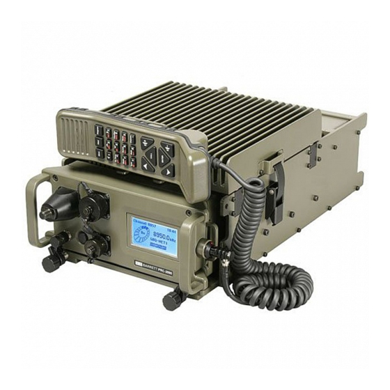
The Barrett 2090 man pack is a DSP based, 500 channel HF SSB transceiver with a frequency range of 1.6 to 30 MHz. The Barrett 2090 is designed using the latest technology enabling a physically small package with a full feature complement. -
Page 13: Operation
Operation User Controls 2090 Front Panel Description 50 ohms antenna socket under whip adaptor Whip and long wire adaptor - when using automatic antenna tuner** Accessory interface connector – for external modems, programming etc. Removable display module – removable to wear on webbing Earth post –... -
Page 14: Using The Handset
Using the Handset Earphone Transmit (PTT) button. Keypad- with touch backlighting Microphone Handset to LCD unit interface cable Detachable LCD unit The handset combines a transmit PTT button, earpiece, microphone and operator keypad. 14 of 246... - Page 15 Use the word ‘over” to indicate you have finished speaking and release the PTT (transmit) button. Note:- the 2090 has a transmit “time-out” facility. This facility (when programmed) allows the transmitter to be keyed in transmit mode with the PTT (transmit) switch for a set time period, after which the transceiver switches to receive until the PTT (transmit button is released and re-keyed.
-
Page 16: Keypad
Keypad There are 21 keys on the keypad. A group of five keys in the centre access many major functions. Some keys have multiple functions assigned to them depending on when the key is pressed and for how long the key is pressed. Key functions are listed below followed by a detailed description of their functions. - Page 17 Key Primary function Secondary function Clear back one step None Enter direct channel change Decimal point mode Alpha “ghi” Enter tuning receiver Numeric key “4" Mode Alpha “tuv” Turn scrambler on / off Numeric key ”8" None Enter program mode Alpha “space”...
-
Page 18: Locking And Unlocking The Keypad
Locking and Unlocking the Keypad The keypad can be locked by the user to stop accidental key press activity. To lock the keypad press and hold down the key. The display will show the following : Once the key has been held down long enough the “Keypad Locked” message will be displayed. - Page 19 Once the key has been held down long enough the “Keypad Unlocked” message will be displayed./ The keypad will automatically unlock when a Selcall or ALE call is received. 19 of 246...
-
Page 20: Transceiver Rear Panel Description
2090 Transceiver Rear Panel Description The rear panel connectors mate with either the battery or the vehicle docking station. Multiway Accessory and Docking station power connector Battery Power Connector 20 of 246... -
Page 21: Switching On The Transceiver
Switching on the Transceiver Switching on the Transceiver – Without a PIN Pressing the power on/off button (please refer to “2090 front panel description” section) turns transceiver on. Switching on the Transceiver – With a PIN Press the power on/off button to turn the transceiver on. -
Page 22: Display
Display Receive Mode In receive mode the LCD display shows:- Channel number Power setting Battery level Mode Time 2090 Icon Receive frequency. Noise reduction activated Channel use Receive signal strength Missed Selcalls received ALE Active Selective Call mode. 22 of 246... -
Page 23: Transmit Mode
Transmit Mode In transmit mode the LCD display shows:- Channel number Power setting Battery level Mode Time 2090 Icon Transmit frequency. Noise reduction activated Channel use Transmit power Missed Selcalls received ALE Active Selective Call mode. 23 of 246... -
Page 24: Secure Mode
Secure Mode In secure mode the LCD display shows:- Date Power setting Battery level Mode Time 2090 Icon Channel number. Noise reduction activated Receive signal strength / Missed Selcalls received Transmit Power Selective Call mode. ALE active 24 of 246... -
Page 25: Channel Attributes
Channel Attributes Pressing and holding down the key for more than 2 seconds will reveal more details about the currently selected channel:- Using the Scroll keys to scroll down will reveal further details:- Note:- when in Secure mode the channel attributes do not show frequencies. 25 of 246... -
Page 26: Adjusting The Audio Volume
Adjusting the Audio Volume To increase the audio volume in the loudspeaker To decrease the audio volume in the loudspeaker The display looks like this when adjusting the volume:- Selecting a Channel Using Channel Up/Down Keys Pressing the channel up or down key will select respectively the next higher or lower programmed channel. -
Page 27: Direct Channel Number Entry
Direct Channel Number Entry press the Enter the channel number required, using the numeric keys, channel range is from 1 to 9999 inclusive. Note:- Channel zero cannot be selected. (example selects channel 12) press the keys press the If the channel selected had not been previously programmed then the following is displayed:- Note: Empty channels can only be accessed by direct channel selection and are not displayed when scrolling through channels. -
Page 28: Barrett Selective Calling System
In addition to the use of the transceiver in simple voice mode to call other stations there are several different types of Selective Calling systems available. The calling systems available for the Barrett 2090 transceiver are listed below:- International A four and six digit Selective Call system, fully interoperable with the UN format published in September 2004 and fully backwards compatible with all previous Barrett 4 digit Selcall protocols. -
Page 29: Selective Call –"Selcall
If Automatic Link establishment (ALE) is in use refer to the ALE section for operation details. Special Notes When Using OEM 1 Selective Call Protocol All 6 digit OEM 1 protocol calls will only be decoded by other Barrett transceivers fitted with OEM 1 Selcall protocol or other manufacturers’ transceivers using encryption. -
Page 30: More Selective Calling Information
More Selective Calling Information Selcall Self IDs As from software version 2.00 the 2050 transceiver can have up to 10 selcall self IDs assigned to it. These Selcall IDs can be any combination of 4 or 6 digit OEM or International type id. -
Page 31: Default Self Ids
Default Self IDs Default self IDs are the IDs used when making a selective call. They are used when the self ID is not set during the call procedure or the Selcall address book entry being used does not have a self ID attached to it. These IDs are also used when making calls via the RS232 control command set. -
Page 32: Detaching An Id From The Default Self Ids
Detaching an ID From the Default Self IDs Detaching an ID from the default IDs will force the operator to select a self ID when making a Selcall. then press the key. press the key until the “Detach Self ID?) screen appears. Use the scroll keys to select the option required. - Page 33 then press the key. 33 of 246...
-
Page 34: Contacting Another Station - Using Selective Call "Selcall" And Telcall
Contacting Another Station - Using Selective Call “Selcall” and Telcall Entering Station IDs and Using the Address and Telephone Books Selcall and Telcall functions described in this section require station IDs or telephone numbers to be entered when making a call. They make use of convenient address and telephone books to allow frequently used Station IDs, station names and telephone numbers to be easily entered. - Page 35 then press the press the key and the last station called will be called again. 35 of 246...
-
Page 36: Changing Self Ids During A Call
Changing Self IDs During a Call During any selective call process pressing the button after the destination address has been entered will continue on with the call process. If the button is pressed and held for 2 seconds then the option of changing the self ID of the call will become available. - Page 37 Use the scroll keys to scroll to a non fixed address book entry. press and hold the key for 2 seconds Use the scroll keys to select the new self ID to be transmitted then press the key to continue the call process. 37 of 246...
- Page 38 Station ID ranges 4 and six digit networks are all accommodated in the 2090 standard Selcall system Station ID range from 000000 to 999999 inclusive (the destination ID must be either 4 or 6 digits long) Calling groups In four digit format...
-
Page 39: When Asked To Enter A Telephone Number
When Asked to Enter a Telephone Number:- Either enter the telephone number using the numeric keypad (a number up to 16 digits) if you think that telephone number is in the phone book use the Scroll keys to find the name and number you want to call:- if you know the name associated with the telephone number in the phone book press the key and either enter the first... -
Page 40: Checking For The Best Channel To Use Between Two Stations - Beacon Call
Checking for the Best Channel to Use Between Two Stations - Beacon Call Before using many of the Selcall and Telcall functions in this section it is useful to know how to use the “Beacon Call” function. "Beacon Call" allows the operator to determine the signal quality between their station and a station they want to call on a particular channel, but without actually alerting the station they are doing so. -
Page 41: Receiving A Beacon Call
Receiving a Beacon Call When a transceiver receives a beacon request call, it responds by transmitting the Beacon Call revertive tones. No indications occur on the transceiver. Beacon Calls are not saved in the Selcall history buffer. Sending a Selcall select the channel you want to send the Selcall on. -
Page 42: Receiving A Selcall
Receiving a Selcall To receive a Selcall your transceiver must be programmed for Selective Call (Selcall) and where multiple channels are in use the scan function should be activated. Receiving a Selcall Directed to Your Transceiver When you receive a Selcall, your station sends a revertive call (to alert the calling station that its call was received), an audible alarm is sounded, the mute (squelch) (if selected) opens and the display shows the call as follows:- The audible alarm will sound for thirty seconds and then time out. -
Page 43: Receiving All Calls, Group Calls And Sub-Group Calls
Receiving All Calls, Group Calls and Sub-group Calls Stations can send a Selective Call that will alert different groupings of mobiles as follows:- In four digit format All call A station sending X000 will be received by stations X000 - X999 (up to 890 stations*) Group call A station sending XX00 will be received by stations XX00 - XX99... -
Page 44: All Call
Receiving an “All call ” , “Group Call”, “Sub-Group Call” When you receive any of the calls above an audible alarm is sounded, the mute (squelch) (if selected) opens and the display shows the call type as follows:- “All call” “Group call”... -
Page 45: Emergency Calls
Emergency Calls Receiving an Emergency Call Barrett transceivers that receive an emergency Selcall emit a distinctive audio alarm and display the following:- If the transceiver sending the emergency Selcall is fitted with a GPS receiver the position will also be displayed as illustrated below :-... -
Page 46: Direct Dial Telephone Calls - Telcalls
Direct Dial Telephone Calls - Telcalls Transceivers equipped with the Telcall option can direct dial telephone numbers and receive calls from telephone users through a Barrett telephone interconnect base stations. Note:- If ALE is in use refer to the ALE section for details. -
Page 47: Last Number Redial
then press the enter the telephone number you want to call (see “Entering station IDs and using the address and telephone books”) then press the wait for the Telcall to be sent. listen for revertive tone from the called station that indicates the call was successful. -
Page 48: Hang Up Call
Hang Up Call When a call to a telephone interconnect base station has been completed the caller should "hang up" by sending a “hang up” code:- press the select “Hang up” with the scroll keys then press the select the ID of the telephone interconnect that you are connected through then press the When the hang up Selcall has completed transmitting, listen for hang up revertive... -
Page 49: Preset/Predialled (Abbreviated Number) Telephone Calls
Preset/Predialled (Abbreviated Number) Telephone Calls A base station equipped with telephone interconnect facilities is also capable of making preset (abbreviated number) telephone calls, these calls are also known as predialled calls. Preset (abbreviated) telephone numbers are stored in the telephone interconnect unit and are accessed by sending a standard Selcall using a specific Selcall number. -
Page 50: Preset (Abbreviated) Selcall Numbering
Preset (Abbreviated) Selcall Numbering Enter xxxxAA or xxAA where xxxx or xx is the (four) six or (two) four digit Selcall ID of the base station equipped with telephone interconnect facilities and AA represents the preset telephone number (between 1 and 98) Example:- Entering 4523 will instruct a telephone interconnected base station with a four digit Selcall ID of 45XX to call preset (abbreviated) number stored as 23 in the telephone... -
Page 51: Fixed And Preset Address Book Entries
Fixed and Preset Address Book Entries Fixed Address Book Entry Address book entries can be programmed to be fixed to certain self IDs via the 2000 Series Programming Software. This stops the transceiver operator from being able to select which self ID is to be used when calling a specific address book entry. -
Page 52: Preset Address Book Entry
Preset Address Book Entry Preset or predialled address book entries are used when the destination transceiver is connected to a telephone interconnect which has preset facilities available. Preset address book entries are fixed and can only be changed via the 2000 Series Programming Software. -
Page 53: Call History
Call History Whenever a Selcall, Telcall, All call, Group call, Sub group call, Pagecall, Statcall GPS or Emergency call is received or transmitted its details are held in a first in first out call history buffer. Received calls that have not been viewed before are held in a section called “New Calls”, received calls that have been viewed are held for future viewing in the “Call inbox”... - Page 54 Hold the key until the “Erase Entry” screen is shown. press the key and the entry will be deleted. To delete all entries from a Selcall history section scroll to the “All Entries” screen then press the key. 54 of 246...
-
Page 55: Scanning Channels
Once the mute closes, for a period greater than the scan dwell period, scanning will resume. The Barrett 2090 transceiver has up to eight scan tables available each table being able to be programmed with up to thirty channels. (See Menus and Programming... -
Page 56: Selecting A Scan Table
Selecting a Scan Table press the key for more than two seconds use the scroll keys to select the scan table number then press the Note:- If no scan tables are programmed the following is displayed:- Initiating Scan Momentarily press the key. -
Page 57: Clarifier
Clarifier The clarifier is used to finely tune the receiver on the selected channel to compensate for received signals from other stations that are off frequency. The receiver can be tuned in the clarifier mode in steps of 1 Hz to frequencies up to -1 kHz and +1 kHz of the assigned channel frequency, depending on programming. -
Page 58: Noise Reduction Selection
Noise Reduction Selection The DSP noise reduction system is enabled and disabled by momentary pressing key. When the noise reduction system is selected the display shows a small square to the right of the mode indication notated NR as below:- The DSP noise reduction system is disabled by momentary pressing the key. -
Page 59: Mute (Squelch) Selection
Mute (Squelch) Selection There are three mute (squelch) modes:- Audio (syllabic) Mute (Squelch) – the receiver audio is enabled when speech is detected on the selected channel. Note:- The syllabic mute sensitivity can be set to three levels, these levels can be set either when programming the transceiver or in the “Mute Settings”... -
Page 60: Mode Selection
Mode Selection The mode key changes the mode of operation - LSB, USB, AM, CW or AFSK of the selected channel. The mode key will only temporarily set the mode for a selected channel, the mode reverting to that channel’s programmed mode after the channel is changed, or the transceiver is turned off. -
Page 61: Advanced Selective Call Functions
Advanced Selective Call Functions Requesting Another Station’s GPS Position select the channel you want to send the GPS request call on. (“Beacon Call” can be used to select the best channel) listen for traffic on that channel, if no traffic is heard then press the select “GPS Request”... - Page 62 Wait for the station you called to send back its position data after which the following will be displayed:- The station called GPS position:- or – the following error messages:- The GPS unit is not providing data to the remote transceiver There is no GPS receiver fitted to the remote transceiver There was no response from the remote station 62 of 246...
-
Page 63: Sending Your Gps Position To Another Station
Note:- The GPS interface option P/N 2090-01-04 must be fitted and the GPS receiver P/N 2090-01-05 must be connected and receiving position information when using the GPS call option. - Page 64 Note:- If the display indicates that the GPS is unavailable as shown below you cannot select the Selective Call function “GPS data. 64 of 246...
-
Page 65: Text Messaging – "Pagecall", "Sms
Text Messaging – “Pagecall”, “SMS” Pagecall allows messages of up to 32 characters in International format or 64 characters in OEM format to be sent or received to and from other transceivers with Pagecall facilities. Sending a “Pagecall” “SMS” select the channel you want to send the Pagecall on. (“Beacon Call”... - Page 66 then press the type in your messages using the alpha numeric keys then press the 66 of 246...
-
Page 67: Receiving A "Pagecall" "Sms
Receiving a “Pagecall” “SMS” When a Pagecall is received an audible alarm is sounded, the mute (squelch) is opened and the display shows the following:- The audible alarm will sound for thirty seconds and then time out. To cancel the alarm before the time out period and to acknowledge the call, press PTT or any key. -
Page 68: Special Characters In A Pagecall
Special Characters in a Pagecall As from V2.00 of transceiver firmware “Pagecall” selective call messages have the ability to send special characters out as part of the message. These special characters are ‘*’, ‘#’ and ‘.’. To get the new characters to display properly the transceiver front panel unit needs to be fitted with V14 or later firmware. - Page 69 To select a ‘.’ character press the key. To select either the ‘*’ or ‘#’ character the transceiver needs to go into ‘Special Character Mode’. To do this press the key. Please note that if V14 or later front panel firmware is not fitted then a ‘?’...
-
Page 70: Remote Station Operational Status – "Statcall
Remote Station Operational Status – “Statcall” “Statcall” allows the operational status parameters of any Barrett transceiver fitted with Selcall to be accessed. This status is sent from the remote transceiver as a Selcall with the status information embedded within the Selcall structure. - Page 71 The status request is being transmitted Your station is waiting for the station you called to send back its “Status data” (which sounds like the remote station sending a Selcall to you) after which the following will be displayed, use the keys to move through the pages:- or –...
-
Page 72: Person To Person(S) Secure Call
Person to Person(s) Secure Call This facility allows a secure voice connection to be made between two or more stations. Note:- In the protected menu “Audio Setting” section, scrambler must be enabled in the “Scrambler section” and in the “Scrambler code” section a 4 digit number entered. -
Page 73: Tuning The Receiver
Tuning the Receiver The 2090 transceiver can be used as a tunable receiver. The receiver can be tuned from 500 kHz to 30 MHz in steps ranging from 1 Hz up to 10 MHz. Press the key to enter the tuning receiver mode:-... -
Page 74: Scanning With The Tunable Receiver
Scanning With the Tunable Receiver The receiver can scan any range of frequencies from 500 kHz to 30 MHz with a frequency step down to 10 Hz. Setting up Scan Frequencies To set up the frequency scan parameters, enter the tuning receiver mode, then:- Press the key for two seconds until the following is displayed:-... -
Page 75: Start Receiver Scanning
Using the Scroll keys select step increment required in Hz (Steps available 100 Hz (0.1 kHz), 250 Hz (0.25 kHz), 1000 Hz (1 kHz), 2500 Hz (2.5 kHz) (example shown 2500 Hz) then press the Using the Scroll keys select step speed in milliseconds. (steps available 100 mS, 250 mS, 500 mS, 1000 mS (example shown 250 mS) then press the... -
Page 76: Menu Functions
Note:- Menu items in both menus can be barred from use, if operationally required, by using Barrett 2050 PC based programming software. Navigating the Menus All sections of the Menus are operated using the similar key press sequences. In... -
Page 77: Standard Menu
Standard Menu Identification keys to scroll back and forth through the identification pages:- Shows transceiver type, transceiver serial number and transceiver options fitted. Shows all firmware versions fitted to transceiver. Show ATU firmware version and antenna selected 77 of 246... - Page 78 This screen shows the default Selcall self ids for OEM and International type selcalls. INT1 is the default 4 digit ID for International or CCIR programmed channels. INT2 is the default 6 digit ID for International or CCIR programmed channels. OEM1 is the default 4 digit ID for OEM programmed channels. OEM2 is the default 6 digit ID for OEM programmed channels.
-
Page 79: Display Options
Display Options Backlight Level Allows the backlight level on the LCD display to be adjusted to one of three viewing levels:-High, Medium or Low. Use the Scroll keys to select the level required (example Medium):- when the level required is displayed press the 79 of 246... -
Page 80: Backlight Timeout
Backlight Timeout Allows the backlight timeout time to be set so the backlight stays on for a short time from the last key press, for a long time from the last key press or so that the backlight is permanently on or off. Note:- Having the backlight off reduces the transceiver’s power consumption. - Page 81 Call History Whenever a Selcall, Telcall, All call, Group call, Sub group call, Pagecall, Statcall GPS or Emergency call is received or transmitted its details are held in a first in first out call history buffer. Received calls that have not been viewed before are held in a section called “New Calls”, received calls that have been viewed are held for future viewing in the “Inbox”...
-
Page 82: Outbox
Outbox This section lists all types of Selcalls that have been transmitted:- Navigation when in the “New calls”, “Inbox” and “Outbox” is always the same as shown in the “New Calls” example below:- Either Use the Scroll keys to select the required record:- enter a record number using the numeric keys and press 82 of 246... - Page 83 In all cases, when a record has been selected, press the key for more details of the call:- If the received Selcall ID is not listed in the transceiver Selcall ID book, associating it with a name, the following will be displayed:- If the channel the incoming Selcall was received on has been deleted since the Selcall was received the following is displayed:- 83 of 246...
-
Page 84: Address Books
Address Books Selcall ID Book – Add a New Entry then press the press key if uppercase is required enter name to be associated with Selcall ID then press key:- 84 of 246... - Page 85 Enter Selcall ID number, four or six digits then press key:- At this point Self IDs can be linked to the Selcall ID entered. This means that when a call is made to this Selcall ID the self ID associated with it will only be used. If no self IDs are available or the self id associated with the destination address is deleted the “Current Link is Invalid”...
- Page 86 If “Yes” is selected use the scroll keys to select the self ID to be associated with the Selcall ID then press key add the new entry:- 86 of 246...
-
Page 87: Selcall Id Book – Edit An Entry
Selcall ID Book – Edit an Entry then press the key. Scroll to the Selcall ID required. then press the key. Enter in the new Selcall ID then press the key. 87 of 246... - Page 88 then press the key. Select the “Linked to Self ID” option. then press the key. If “Linked to Self ID” is set to “Yes” then the original self id is displayed. Use the scroll keys to select the new self ID to link to if required, then press the key.
-
Page 89: Selcall Id Book – Erase An Entry
Selcall ID Book – Erase an Entry then press the key. key for more than two seconds. The erase press the entry verification screen will appear unless the address book entry is fixed. If this is the case then an error will be displayed on the screen. - Page 90 use the Scroll keys to select “Yes” to erase the address book entry. then press the key. 90 of 246...
-
Page 91: Phone Book - Add A New Entry
Phone Book - Add a New Entry press the key if uppercase required enter the name to be associated with telephone number then press the 91 of 246... - Page 92 enter the telephone number using the numeric keys (up to 16 digits) then press the 92 of 246...
-
Page 93: Phone Book - Edit An Entry
Phone Book - Edit an Entry Either use the Scroll keys to scroll though the phone book to find the entry you want to edit enter the first letter of the name you are looking for using the Alpha keys, for example, looking for the name Patrick:- Key in ‘p’... - Page 94 enter the new telephone number using the numeric keys (up to 16 digits):- then press the 94 of 246...
-
Page 95: Phone Book - Erasing An Entry
Phone Book - Erasing an Entry select the entry you want to erase using the Scroll keys. press the key for more than two seconds use the Scroll keys select “Yes” 95 of 246... - Page 96 then press the 96 of 246...
-
Page 97: Ale Autofill Book
ALE Autofill Book If the transceiver has the ALE option fitted then the ALE Auto fill address book menu will be available. See the ALE section of the manual for more information on the auto fill function. If no auto fill calls have been received and the ALE auto fill is enabled then the display will show: Or, if auto fill calls have been received and the ALE auto fill is enabled then the display will show:... -
Page 98: Ale Autofill Book – Reassign An Entry
ALE Autofill Book – Reassign an Entry Each time an auto fill call is received the calling station information is stored in a queue, on a first in first out basis once the auto fill queue is full. To permanently save an incoming auto fill call into the transceivers ALE network the alias needs to be reassigned. - Page 99 then press key to save the new alias:- 99 of 246...
-
Page 100: Ale Autofill Book – Erase An Entry
ALE Autofill Book – Erase an Entry To erase an auto fill id go to the Auto fill book menu item, then press the key, use the scroll keys to scroll through the received auto fill calls. Once the correct ID has been selected press the key for more than two seconds Use the scroll keys to select yes then press the... -
Page 101: Audio Scrambler
Audio Scrambler When using the internally fitted audio scrambler accessory PCB that provides backwards compatibility to the 900 series audio inversion scrambler (BCA20031) or the Transcrypt scrambler (BCA20054), the scramble code is set using this option. All stations using the scramblers require the same scrambler code to be entered:- The code can be selected between 1 and 16 for the Transcrypt scrambler (BCA20054) or 1 and 32 for the audio inversion scrambler (BCA20031):-... -
Page 102: To Enable Scrambled Mode
To Enable Scrambled Mode Press the key for more than two seconds, the “Scrambler Enabled” screen will be shown. While the transceiver is in scrambled mode the “Scrambler On” message will be displayed. To Disable Scrambled Mode Press the key for more than two seconds, the “Scrambler Disabled”... -
Page 103: Antenna Select
Antenna Select This section allows the selection of the antenna type to be used with the 2090 manpack. When an un-tuned antenna such as the whip or a long-wire is to be used “Whip/Long-wire” is selected. This enables the automatic antenna tuner. If a 50 ohm broadband antenna or a tuned dipole is to be used select “50 ohm”. -
Page 104: Protected Menu
Protected Menu Refer page 57 for details on how to access the protected menu. General Microphone Up/Down Keys The keys on the top of the microphone can be assigned for two different functions, either as channel up/down keys or as volume control keys or they can be disabled:- Use the Scroll keys to select the setting required (example “Mic keys disabled”):- press the... -
Page 105: Transmit "Over Beep
Transmit “Over Beep” When selected the 2090 transceiver transmits a short tone when the PTT is released. It provides an audible indication to the operator at the remote station that the local station has stopped transmitting. Use the Scroll keys to select the setting required (example “Tx Over Beep enabled”):-... -
Page 106: Transmit Timeout
Transmit Timeout When this feature is enabled the 2090 transceiver will disable the transmitter if the PTT (push to talk button on the microphone) is held on for more than the time limit set below i.e. if the microphone is inadvertently jammed under a seat. Releasing the PTT will reset the transmitter. -
Page 107: Channel Labels
Channel Labels This section enables the adding, editing or erasing of channel use labels, these labels are used during channel programming to indicate what particular channels are used for i.e. UNHCR Geneva:- Edit Labels Either use the scroll keys to scroll through to the label you want to edit:- search for label you want to edit by entering the first letter of the label and using the scroll keys to select it:-... -
Page 108: Delete A Label
edit the entry when editing is complete press the Delete a Label Enter edit mode as shown above and select the label you want to delete:- press the key until the display below appears:- Use the scroll keys to select “Yes” you want to delete the entry:- then press the key. -
Page 109: Add An Entry
Add an Entry press the type in a new label using the Alpha keys:-. then press the key. 109 of 246... -
Page 110: Setting The Clock
Setting the Clock press the Use the Scroll keys and as shown on the screen to set the current time for example 13:15 (1:15 PM):- When time is set press the key. 110 of 246... -
Page 111: Setting The Date
Setting the Date press the Use the Scroll keys and as shown on the screen to set the current date for example 04 June 2004:- When date is entered press the 111 of 246... -
Page 112: B.i.t.e. Test
B.I.T.E. Test This section runs the transceiver’s Built-in Test Equipment (B.I.T.E.) tests. The transceiver checks vital transceiver functions and reports the results as shown below:- press the then press the key to continue:- press the key to repeat the test or press the to finish. -
Page 113: Option Installation
Option Installation Options are installed in the Barrett 2090 transceiver by entering a PIN supplied by the manufacturer. This PIN is related to the electronic serial number of the transceiver. A different PIN is provided depending on the option or combination of options required to be fitted. -
Page 114: Secure Call Code
Secure Call Code When using the person to person voice scrambler both stations require the same scrambler code to be entered:- Using the numeric key pad enter a four digit number:- then press the 114 of 246... -
Page 115: Security Level
Security Level This option allows the user to set the level of security used during secure voice communications. It changes the number of hops per second used by the encrypting algorithm. There are 2 choices: High – 25 hops / second in Frequency Hopping mode 15 hops / second in Secure Call mode Standard –... -
Page 116: Upload Pack
Upload Pack See section “Cloning (programming) from another transceiver” 116 of 246... -
Page 117: Internal Modem
Internal Modem This menu option allows the user to enable or disable the internal HF data modem functionality of the transceiver. press the use the scroll keys to select the required setting then press the 117 of 246... - Page 118 press the Note:- Once the “Internal Modem” option is enabled, transceivers cannot be controlled or programmed via RS232 communications. The “Internal Modem” must be disabled to allow re-programming or control of the transceiver through RS232 communications. 118 of 246...
-
Page 119: Scan Tables
Scan Tables Adding Channels to a Scan Table Use the Scroll keys to select the channel you wish to add:- When the channel required is displayed press the 119 of 246... -
Page 120: Editing Channels In A Scan Table
Editing Channels in a Scan Table Either Use the Scroll keys to select the channel you wish to edit:- Select the channel you wish to edit by entering the channel number (example channel 1):- then press the 120 of 246... -
Page 121: Erasing Entries In A Scan Table
Then press the key to edit the channel number Use the Scroll keys to select the new channel for the scan table slot:- press the key to enter the new setting:- Erasing Entries in a Scan Table Select the scan table and channel slot you want to remove using the steps above:- when the entry you wish to erase is selected press the until the following is displayed:-... - Page 122 then press the Note:- All channels are displayed in numerical order within the scan table with respect to the entry number, there are a maximum of 30 entries in each table. 122 of 246...
-
Page 123: Changing Scan Table Labels
Changing Scan Table Labels press the Use the key to clear the old label:- using the alpha/numeric keypad enter the new label:- 123 of 246... - Page 124 then press the 124 of 246...
-
Page 125: Scan Settings
Scan Settings Scan Rate Selects the scan rate applicable to non-Selcall scan channels, selectable between 300 mS and 5 seconds per channel. Use the Scroll keys to select the scan resume time required (example 700 mS):- When the setting required is selected press the 125 of 246... -
Page 126: Scan Dwell
Scan Dwell Selects the length of time the transceiver dwells(waits) on a channel after scan has been stopped by signal strength level (if signal strength level mute is set) or voice activity (if audio mute is set). The dwell time can be set from 1 to 10 seconds. Use the Scroll keys to select the scan dwell time required (example 5 seconds):- When the setting required is selected press the... -
Page 127: Scan Resume Time
Scan Resume Time This section sets the time period after which the Barrett 2090 transceiver will automatically resume scanning from the last operation i.e. key press or PTT. The scan resume time period can be set between 1 and 30 minutes or it can be disabled. -
Page 128: Scan Table Select
Scan Table Select This section selects the Scan table to be used when the transceiver is put in scan, or if enabled, when scan resume occurs. There are 8 scan tables. Note:- When scrolling through the scan tables, before selection, only those with channels entered will be displayed. -
Page 129: Mute Settings
Mute Settings Syllabic Mute Sensitivity The sensitivity or “hardness of the syllabic mute (squelch) is set by this section. The mute can be set between low, medium and high sensitivity to voice activity on a channel. Use the Scroll keys to select the setting required (example High):- When the setting required is selected press the 129 of 246... -
Page 130: Signal Strength Mute Level
Signal Strength Mute Level This section selects the level at which the Signal Strength Level (SSL) mute (squelch) opens. Levels available are low, medium and high. When set to low the mute will open on a relatively low level of received signal, when set to high the mute will open on a relatively high level of received signal. -
Page 131: Selcall Settings
Selcall Settings Self IDs This allows the operator to set up all the self IDs for the transceiver. Up to 10 self IDs can be assigned. Any combination of 4 and 6 digit ID is permitted. Any combination of International or OEM Selcall type is also permitted. Adding Self IDs then press the key. - Page 132 enter name to be associated with the Selcall ID, press key if uppercase required. then press key:- Use the scroll keys to select the Selcall ID format then press the key:- 132 of 246...
-
Page 133: Modifying Self Ids
Modifying Self IDs then press the key. Scroll to the ID required. then press the key. Change the ID name if required. 133 of 246... - Page 134 then press the key. Change the Selcall format associated with the ID if required. then press the key. 134 of 246...
-
Page 135: Deleting Self Ids
Deleting Self IDs then press the key. use the Scroll keys to select the entry you want to erase. press the key for more than two seconds. The erase entry verification screen will appear unless the ID is set as a default ID or is attached to a fixed address book entry. - Page 136 The self ID is attached to an address book entry which is fixed. To delete this self ID the address book entry must be modified in the 2000 Series Programming Software to have the self ID detached from it. The self ID is set as one of the 4 default self IDs. To delete this self ID it must be removed from the default ID list.
-
Page 137: Selcall Int 1 – Setting Default International 4 Digit Selcall Self Id
Selcall INT 1 – Setting Default International 4 Digit Selcall Self ID Selcall INT1 - Used as the default 4 digit International or CCIR (WA2 in Australia) self ID when sending calls. Selcall INT 2 – Setting Default International 6 Digit Selcall Self ID Selcall INT1 - Used as the default 6 digit International self ID when sending selective calls. -
Page 138: Selcall Oem 2 – Setting Default Oem 6 Digit Selcall Self Id
Selcall OEM 2 – Setting Default OEM 6 Digit Selcall Self ID Selcall OEM2 - Used as the default 6 digit OEM self ID when sending selective calls. Note:- We recommend that the self ID should not be set to X000, XX00 or XXX0 as these are reserved Selcall numbers for Allcall, group-call or sub-group-call use. -
Page 139: Selcall Alarm
Selcall Alarm The Selcall received audio annunciation can be turned on or off using this function; this is useful when the transceiver is used in covert operations. Reception of the Selcall continues to be displayed visually on the display. Use the Scroll keys to select the setting required (example shows selection of alarm “On”):- press the 139 of 246... -
Page 140: Selcall Transmit Tones Audio Level
Selcall Transmit Tones Audio Level To confirm transmission of a Selcall the Selcall tones are normally output on the transceiver loudspeaker. In certain situations this is not required or the tone volume requires adjusted. This section allows the Selcall audio to be disabled or set to two volume settings, Low or High. -
Page 141: Selcall Pre-Amble Length Setting
Selcall Pre-amble Length Setting The Selcall pre-amble length can be set between 1 and 10 seconds depending on how many channels are used in the scan table being used. Allow 500 mS for each Selcall channel to be scanned plus one second, E.g. to scan 8 Selcall channels:- 500 mS x 8 + 1 sec. -
Page 142: Txcvr Lock
TXCVR Lock This section enables the network operator to send a special key (programmed into a transceiver during programming) by Selcall to disable that transceiver. transceiver remains locked until an unlock code is entered. This function can be used if the transceiver has been stolen and it is being used illegally. - Page 143 The transceiver will now send the lock call. A revertive call from the transceiver being locked will confirm the action. A transceiver that has been locked by this process can only be unlocked by using the Barrett programming software. See the programming software for details. 143 of 246...
-
Page 144: Oem Privacy Key
OEM Privacy key When using OEM Selcall protocol, OEM calls can either be sent plain text or encrypted. This is done by using either the privacy key programmed by the programming software or if no privacy key is programmed the default value of 9999999. -
Page 145: Audio Settings
Audio Settings Audio Bandwidth This section allows the audio bandwidth to be tailored to an operator’s comfort requirements. Settings available are full bandwidth - 300 Hz – 1.5 kHz, 300 Hz – 2.0 kHz, 300 Hz – 2.5 kHz , 300 Hz – 3.0 kHz. Use the Scroll keys to select the audio bandwidth required (example “300Hz to 2.5 kHz”):- When the audio bandwidth required is displayed press the... -
Page 146: Beep" Volume Level
“Beep” Volume Level This section is used to set or disable the annunciation beep volume levels. These are the various tones associated with key presses. In covert operations these can be disabled, in other operations these are set for operator comfort. Settings are “Off”, “Low”... -
Page 147: Receiver Audio Path Configuration
Receiver Audio Path Configuration The section sets where the unprocessed receiver audio in the transceiver is sourced. Normally this is set to internal; in this case the transceiver’s receiver provides the unprocessed audio. When used with a remote receiver, in split site operations, it can be set to external, in this case unprocessed receive audio from the remote site can be input into the auxiliary sockets 600 ohm balanced audio port. -
Page 148: Transmitter Audio Path Configuration
Transmitter Audio Path Configuration The section sets where the transmitter audio in the transceiver is sourced. Normally this is set to internal; in this case the transceiver’s microphone provides the transmitter audio. When used with a remote site operation, it can be set to “remote”, in this case the transmit audio is input into the auxiliary sockets 600 ohm balanced audio port. -
Page 149: Line Audio
Line Audio This section sets the muting condition of the 600 ohms balanced audio line output on the rear auxiliary connector. The line output can be set to “Un-Muted” or “Follows Mute”. When set to “Follows Mute” the line output is muted in the same manner as the speaker output and follows the mute condition currently in use. -
Page 150: Noise Reduction
Noise Reduction This section allows the DSP noise reduction “depth” to be adjusted to suit the operator’s comfort requirements. Settings available are Weak, Medium and Strong. It should be noted that as the “depth” is increased the processed human voice gets a more metallic quality. -
Page 151: Rf Settings
RF Settings Optional IF Filter Enable When enabled the optional IF filter (if physically fitted) is selected automatically when AFSK or CW mode is selected. This is useful when the transceiver is used in some data transmission applications. Use the Scroll keys to select the setting required (example shown “Enabled”):- press the Note:- This setting is only available if the narrow filter setting is selected during... -
Page 152: Receiver Pre-Amplifier
Receiver Pre-amplifier Enables or disables RF preamplifier, this preamplifier provides and additional receiver gain of 5dB. Generally the RF pre-amplifier is switched off when an automatic mobile antenna is in use as these antenna have an inbuilt RF pre-amp. Use the Scroll keys to select the setting required (example shown “Enabled”):- press the 152 of 246... -
Page 153: Clarifier Range
Clarifier Range This menu item allows the user to set the clarifier range or disable the clarifier; the range can be set to +/-50 Hz, +/-150 Hz or +/-1 kHz. Use the Scroll keys to select the clarifier range required (example shown +/-1 kHz):- When the clarifier limit required is displayed press the 153 of 246... -
Page 154: Noise Blanker Threshold
Noise Blanker Threshold This menu item allows the predictive noise blanker to be switched on or off and allows the selection of three threshold levels. The noise blanker is useful to reduce the interference caused within vehicles with petrol engines. Note:- The noise blanker will not be effective in situations where external power line noise etc is blanketing the receiver. -
Page 155: Agc Hang
AGC Hang This section allows the AGC configuration of the receiver to be set to either “Hang ACG” or “Hang Off”. The selection depends on the receiver environment and should be set for optimum receiver performance. In the presence of high static and sporadic noise, the function of the hang AGC may result in gaps in the received signal due to the slow AGC recovery. -
Page 156: I/O Settings
I/O Settings RS-232 Out This section enables or disables RS-232 Selcall information output from the transceiver via the 25 pin auxiliary connector. Use the Scroll keys to select the setting required (example shown “Enabled”):- When the setting required is displayed press the Note:- This command does not allow RS-232 control of the transceiver as enabled when the RS-232 option is fitted. -
Page 157: External Alarm
External Alarm This section sets the action of the external alarm output, on pin 17 of the 25 pin D auxiliary connector, activated when a Selcall is received by the transceiver. It can be set to either a pulse output (for use with a horn) where the output is activated 15 seconds on, 15 seconds off;... -
Page 158: Antenna Type
Antenna type This section sets antenna type or if a linear amplifier is to be used with the 2090 manpack fitted into the 2090 Vehicle docking. Selections available:- “Base Station” Select when base station antennas such as the Barrett 2012 series are used. No tuning signals are emitted on channel change. - Page 159 Use the Scroll keys to select the type of antenna or a linear amplifier (example shown “2019 Mobile antenna):- When the setting required is displayed press the 159 of 246...
-
Page 160: Gps Receiver Enable
–“Enabled”):- press the Note:- An external GPS receiver is required for GPS functions. If this option is enabled and a GPS is not connected to the 2090 a warning message will appear on the display “GPS Unavailable” 160 of 246... -
Page 161: Line Output Level Adjust
Line Output Level Adjust This section adjusts the output level of the auxiliary 600 ohm balanced audio output port. The level can be set to -6dBm,-3dBm, -0dBm, +3dBm, +6dbm and +9dBm. Use the Scroll keys to select the level required (example shown - 3dBm):- When the level required is displayed press the 161 of 246... -
Page 162: Line Input Level Adjust
Line Input Level Adjust This section adjusts the input level sensitivity of the auxiliary 600 ohm balanced audio input. Sensitivity can be adjusted to -24dBm,-18dBm, -12dBm, -6dBm and 0dBm. Use the Scroll keys to select the level required (example shown - 12dBm):- When the level required is displayed press the 162 of 246... -
Page 163: Automatic Link Establishment (Ale) (Option)
The Barrett 2090 ALE controller’s powerful memory stores up to 10,000 sets of LQA information, 100 channel configurations, 20 self-address configurations and 100 other address configurations. -
Page 164: To Commence Scanning
“ALE scan list select” in the ALE protected menu. Press the the 2090 transceiver will now be ALE scanning and ready to accept ALE calls, receive “Soundings” and transmit “Soundings” (If “Sounding” is enabled on your transceiver) -
Page 165: Linking To Another Station In An Ale Network
Linking to Another Station in an ALE Network press the select “ALE Call” with the scroll keys then press the select the station ID of the station you wish to call (the “To” ID) (see the section below “Selecting ALE Station IDs) then press the select the station ID you are calling from (your self ID can be varied, (the “From”... - Page 166 then press the the ALE call sequence will now commence:- linking in progress:- the link is established, an audible alarm will sound after which you can start communication with the station you called:- Or if you already had two links established:- The following error messages may be displayed:- 166 of 246...
- Page 167 For various reasons the link attempt failed i.e. no response from the called station or the link was rejected by the called station:- You attempted to make a call but for various reasons the system cannot make the call i.e. incorrect self address, no presets available, no valid LQA’s available:- 167 of 246...
-
Page 168: Making A Netcall
Making a Netcall A maximum of 20 networks, programmed with the ALE fill software can be called using the Netcall facility. Each network can consist of up to 15 ALE stations. press the select “ALE Call” with the scroll keys then press the select the network you wish to call (the “To”... - Page 169 then press the the ALE call sequence will now commence:- linking in progress:- the link is established, an audible alarm will sound after which you can start communication with the station you called:- Or if you already had two links established:- The following error messages may be displayed:- 169 of 246...
- Page 170 For various reasons the link attempt failed i.e. no response from the called station or the link was rejected by the called station:- You attempted to make a call but for various reasons the system cannot make the call i.e. incorrect self address, no presets available, no valid LQA’s available:- 170 of 246...
-
Page 171: Sending An Ale Text Message To Another Station In An Ale Network
Sending an ALE Text Message to Another Station in an ALE Network press the select “ALE Message” with the scroll keys:- then press the select the station ID of the station you wish to call (the “To” ID) (see the section below “Selecting ALE Station IDs) then press the select the station ID you are calling from (your self ID can be varied, (the “From”... - Page 172 then press the use the Scroll keys to select either:- If you selected “New Message”:- then press the Enter the message using the alpha/numeric key pad 172 of 246...
- Page 173 If you selected “Preset Message”:- press the Use the Scroll keys to view the rest of the message:- Or use the keys to select other preset messages:- 173 of 246...
- Page 174 When the “Preset Message” is selected or the “New Message” is entered, press the the ALE call sequence will now commence:- linking in progress:- the link is established, an audible alarm will sound after which you can start communication with the station you called:- or if you already had two links established:- The following error messages may be displayed:- 174 of 246...
- Page 175 For various reasons the link attempt failed i.e. no response from the called station or the link was rejected by the called station:- You attempted to make a call but for various reasons the system cannot make the call i.e. incorrect self address, no presets available, no valid LQA’s available:- 175 of 246...
-
Page 176: Telephone Call To Ale Stations With Telephone Interconnect Facilities
Telephone Call to ALE Stations with Telephone Interconnect Facilities press the select “ALE Phone” with the scroll keys then press the select the station ID of the station you wish to call (the “To” ID) (see the section below “Selecting ALE Station IDs) then press the select the station ID you are calling from (your self ID can be varied, (the “From”... - Page 177 then press the Either enter the telephone number using the numeric keypad (a number up to 16 digits) if you think that telephone number is in the phone book use the Scroll keys to find the name and number you want to call:- if you know the name associated with the telephone number in the phone book press the key and either enter the first...
- Page 178 the ALE call sequence will now commence:- linking in progress:- the link is established, an audible alarm will sound after which you can start communication with the station you called:- if you already had two links established:- The following error messages may be displayed:- For various reasons the link attempt failed i.e.
- Page 179 You attempted to make a call but for various reasons the system cannot make the call i.e. incorrect self address, no presets available, no valid LQA’s available:- 179 of 246...
-
Page 180: Selecting Ale Station Ids
ALE network station IDs are pre-programmed into your transceiver. This is usually performed by your network administrator prior to deployment using the Barrett ALE fill program via the RS-232 port on the Auxiliary socket from a PC or Laptop Note:- the same method is used to select the “To”... -
Page 181: Receiving An Ale Call
Receiving an ALE Call Various types of ALE call can be received as described below. When an ALE call to your station commences the following is displayed on your transceiver:- A station in the ALE net is attempting to establish a link to your station:- Your station is now linked, an audible alarm sounds:- This is a normal call and conversation can now commence. - Page 182 An address has matched an incoming Anycall. An Anycall is a special call type that may link with any station(s) listening. Stations respond to Anycalls in random slots. An address has matched an incoming Allcall. An Allcall is a special call type that may link with any station listening. Stations do not respond to Allcalls.
- Page 183 Pressing the key displays the link status:- if more than one link is in progress (example 3 links):- 183 of 246...
-
Page 184: Receiving An Ale Message
Receiving an ALE Message When an ALE link to your station commences the following is displayed on your transceiver:- A station in the ALE net is attempting to establish a link to your station:- Your station is now linked and has received an ALE message, an audible alarm sounds:- If after 60 seconds no key has been pressed the alarm will stop and regular ‘blips’... - Page 185 Pressing the again shows the address of the station that called you:- Pressing returns you to the previous screen etc. Pressing the key or using PTT will return you to the main screen. 185 of 246...
-
Page 186: Receiving An Ale Telephone Call
Receiving an ALE Telephone Call If the RS-232 output is disabled (see I/O section of the Protected Menu) ALE telephone call requests are displayed on the transceiver front panel as follows:- When an ALE link to your station commences the following is displayed on your transceiver:- A station in the ALE net is attempting to establish a link to your station:-... - Page 187 Note:- Normally when using this ALE telephone number function the receiving transceiver is connected to a automatic telephone interconnect unit such as the Barrett 960 or Barrett 2060, in this case the RS-232 output is enabled the receipt of an ALE telephone call request is not displayed as above and the telephone interconnect takes control of the transceiver.
-
Page 188: Receiving An Ale Netcall
Receiving an ALE Netcall When an ALE link to your station commences the following is displayed on your transceiver:- A station in the ALE net is attempting to establish a link to your station:- Your station is now linked, an audible alarm sounds:- Your address has matched an incoming Netcall, a call to a number of stations in one call. - Page 189 Pressing returns you to the previous screen etc. Pressing the key or using PTT will return you to the main screen. 189 of 246...
-
Page 190: Closing Individual Ale Links
Closing Individual ALE links You must be linked to close an ALE link:- if more than one ALE link is in progress (example 3 links):- hold the key until the screen showing status of the current links appears:- use the Scroll keys to select link you wish to close (example shown - a link with a station not in your ID book):- then press the 190 of 246... - Page 191 At this point you can either send a message, in which case go to the section “Sending an ALE text message to another station in an ALE network” or you can terminate the link:- To terminate the link use the Scroll keys to select “Terminate Link”:- press the The link is now terminated and unless you are linked to more than...
-
Page 192: Closing All Ale Links
Closing all ALE Links You must be linked to close an ALE link:- if more than one ALE link is in progress (example 3 links):- press the select “Terminate All Links” with the scroll keys then press the The ALE system now terminates all open links. 192 of 246... -
Page 193: Remote Station Closes The Ale Link
Remote Station Closes the ALE Link If the station you are linked to closes the link the following will be displayed:- Your station will then return to ALE scanning (assuming your station was in ALE scan mode before the ALE link occurred:- 193 of 246... -
Page 194: Combined Ale / Selective Call Capability
“ALE scan list select” in the ALE protected menu. Press the the 2090 transceiver will now be ALE scanning and ready to accept ALE calls, receive “Soundings” and transmit “Soundings” (If “Sounding” is enabled on your transceiver) -
Page 195: Transmitting An Ale Call
This is displayed when your station transmits a “sounding” Note:- Your station would have to have “Sounding” enabled. Transmitting an ALE Call Please refer to the “Linking to Another Station in an ALE Network” section. Receiving an ALE Call Please refer to the “Receiving an ALE link request” section. Receiving and Transmitting a Selective Call (Selcall) Please refer to the “Contacting another station –... -
Page 196: Ale Configuration Menus
ALE Configuration Menus ALE State This feature enables or disables the ALE system Use the Scroll keys to select the setting required (example “ALE Enabled”):- When the setting required is selected press the 196 of 246... -
Page 197: Ale Autofill
ALE Autofill This feature enables or disables the ALE Autofill option. The Autofill option allows the 2050 transceiver to automatically add unknown stations to the ALE network. This means that whenever a new station is added to the network the network administrator does not have to individually re-configure each station in the network with the new stations ID. -
Page 198: Ale Scan List
ALE Scan List Note:- you can also enter this scan list select section by holding down the key for more than two seconds To select the ALE scan list required press the Use the Scroll keys or press the first letter of the scan list you want to use (example shown –... -
Page 199: Auto Transmit
Auto Transmit When Auto Transmit is set to “Disable” the ALE system will not respond to any calls made to this station. Use the Scroll keys to select the setting required (example “Enable”):- When the setting required is selected press the 199 of 246... -
Page 200: Transmit Control
Transmit Control When Transmit Control is set to “Disabled” the ALE system will not be able to transmit any ALE calls, including automatic soundings and responses to incoming ALE calls. Use the Scroll keys to select the setting required (example “Enabled”):- When the setting required is selected press the 200 of 246... -
Page 201: Sounding Control
Sounding Control ALE operates normally both transmitting and receiving sounds when Sounding Control is set to "Enable”. In some circumstances however it is desirable not to transmit soundings under any circumstances, in this case Sounding Control is set to “Disable”. Sounding is limited to certain channels (pre-programmed by the ALE fill program). -
Page 202: Sounding Address
Sounding Address Configures the self address used during an automatic sounding (Sounding Control must be set to Global On). If sounding control = individual preset basis, the address used is dependant on the active channel. Use the Scroll keys to select the setting required (example “FIELDBASE2”):- When the setting required is selected press the 202 of 246... -
Page 203: Link Quality Analysis (Lqa) Exchange
Link Quality Analysis (LQA) Exchange This option enables or disables the exchange of LQA information with other stations Use the Scroll keys to select the setting required (example “Enabled”):- When the setting required is selected press the 203 of 246... -
Page 204: Link Quality Analysis (Lqa) Exchange Mode
Link Quality Analysis (LQA) Exchange Mode This option sets the source of the LQA reading sent to the other station, it can be set to “Current LQA” which is a reading taken during the ALE burst just received or it can be set to “Averaged LQA” which uses the long term averaged value taken from memory. -
Page 205: Link Quality Analysis (Lqa) Averaging
Link Quality Analysis (LQA) Averaging This option sets the method used to update an existing link quality value stored in ALE processor memory when the new link quality value is worse than the stored value. The option can be set to either replace the old values with the new values or replace the old values with different weighted averages of the old values and new readings. -
Page 206: Link Quality Analysis (Lqa) Decay Rate
Link Quality Analysis (LQA) Decay Rate This option sets the artificial decay rate for the link quality information that is stored in the link quality table within the ALE processor. Switching the sounding off and setting a decay rate of two hours would result in the recording of a perfect channel (100% channel quality) decaying to an unusable channel (0% channel quality) over a period of two hours. -
Page 207: Threshold Test
Threshold Test Used to select which type of threshold test is used to determine what quality ALE channel is acceptable for communication. Either “Sinad”, “BER”, “Both” or “None” can be selected. Use the Scroll keys to select the test required (example “BER”):- press the 207 of 246... -
Page 208: Sinad Threshold
SINAD Threshold This option sets the SINAD threshold at which an ALE channel is considered usable. This can be set to between 0 and 30dB. press the using the numeric keys enter the SINAD threshold required (example “12dB”):- then press the 208 of 246... -
Page 209: Ber Threshold
BER Threshold This option selects the BER threshold at which an ALE channel is considered usable. If the required BER is not reached in the reply from the remote station the link establishment process is rejected. Depending on the retry setting the link establishment would continue on another link. -
Page 210: Ale Fill Mode
ALE Fill Mode The ALE is configured with its entire network data using the Barrett PC based ALE fill program. Refer to the Barrett 2050 PC based programming software that contains the ALE fill program for details. 210 of 246... -
Page 211: Programming Functions
The Barrett 2090 transceiver can be programmed in three ways:- Using the software supplied with the programming kit (P/N 2090-01-30), loaded on a PC, and transferring information to the 2090 by RS-232 through the auxiliary connector. By direct key entry through the front panel Note:- This facility may not be available if the network administrator has barred the function during programming using a PC. -
Page 212: Programming A Channel From The Front Panel
Programming a Channel from the Front Panel Note:- To program a channel from the front panel it is necessary to have this function enabled. To enter the programming mode first select the channel you want to program then press the key:- Transmit and Receive Frequencies Use the numeric keypad to enter the receive frequency... -
Page 213: Channel Use Labels
Channel Use Labels Use the Scroll keys to select the required channel label Note:- channel labels can be entered in the “General” section of the protected menu. then press the Operating Mode Use the Scroll keys to select the required operating mode, USB, LSB, AM, CW or AFSK then press the Note:- If the 500 Hz or narrow filter hardware option is enabled... -
Page 214: Transmitter Power Setting
Transmitter Power Setting Use the Scroll keys to select the required output power – high, medium or low power. then press the Selcall Format Each channel can be programmed for one Selcall format, for a description of the formats available, refer to the beginning of this manual. - Page 215 The channel program sequence can be aborted at any stage in the programming sequence by pressing the key after which the following is displayed:- 215 of 246...
-
Page 216: Cloning (Programming) From Another Transceiver
Note:- Use the transceiver you want to send the configuration from for the following steps This feature is used to send a copy of the configuration of one 2090 transceiver or 2090 transceiver fitted in the manpack adaptor to another using a cable (BCA204020) connecting both transceivers together via their auxiliary connectors using the RS-232 connection. - Page 217 Using the numeric keypad enter Six digit ID and press the then press the key to proceed with cloning. 217 of 246...
-
Page 218: Manpack Operation
The Barrett 2090 transceiver uses a removable 10Ah Lithium Ion battery cartridge. This cartridge contains the battery and the battery management system. It has a connector that is used for charging and operating the 2090 when connected to the 2090 or charging the battery when not connected to the 2090. - Page 219 Universal AC/DC Power Adaptor P/N 2090-03-01 For operation from a mains voltage between 100-254VAC or from 12VDC sources such as available in a vehicle:- Rapid Deployment Solar Panel P/N BCA209010 219 of 246...
- Page 220 Rapid Deployment Hand Crank Generator P/N 2090-03-04 220 of 246...
-
Page 221: Charging A 10Ah Lithium Ion Battery Cartridge Outside The Manpack
Charging a 10Ah Lithium Ion Battery Cartridge Outside the Manpack The 2090 battery cartridge can be charged outside the manpack using the AC/DC input universal power adaptor unit or directly from a 24V solar panel or a 24V hand crank generator configured as shown in the following diagrams:-... - Page 222 222 of 246...
- Page 223 Rapid Deployment Hand Crank Generator P/N 2090-03-04 223 of 246...
-
Page 224: Battery Charge Indicator When Charging The 2090
Battery Charge Indicator when Charging the 2090 When the charging source is connected to the 2090 and the transceiver is switched on, the battery icon between the channel number and the time shows the progress of the charge process:- The battery icon with a moving line running from left to right... -
Page 225: Operation In The Manpack Configuration
Operation in the Manpack Configuration Using the Display / Handset Extender Interface (P/N BCA209013) The 2090 manpack LCD unit can be removed from the manpack itself and placed into the LCD unit pouch located on the manpack bag using the extension kit supplied. - Page 226 Step 3: Push LCD blanking (metal face side up) unit into the manpack. Step 4: Connect LCD unit to the unconnected end of the extender cable. 226 of 246...
-
Page 227: Manpack Operation Using The Automatic Antenna Tuner
Manpack Operation Using the Automatic Antenna Tuner The 2090 manpack can be used with the 10 metre throw over long-wire provided or the optional 3 metre collapsible whip. Note:- Either the whip or the long-wire can be used but not both together. -
Page 228: Using The Emergency Long Wire Antenna (P/N 2090-02-06)
Using the Emergency Long Wire Antenna (P/N 2090-02-06) The long-wire antenna should be unfurled and the end away from the manpack transceiver should be attached to any structure available and as high as possible. Note:- When using an un-tuned antenna such as the whip or the long-wire the section “Antenna Select”... -
Page 229: Using The Counterpoise Earth Kit - Multi-Wire (P/N 2090-02-08)
When using either a whip or the long-wire antenna efficiency can be increased by the use of the counterpoise supplied. This is connected to the 2090 via the BNC connector connected to the counterpoise. The three radials should be spread out... -
Page 230: Operation Of The 2090 Manpack In Temporary Base Stations
Operation of the 2090 Manpack in Temporary Base Stations For temporary base station operation, the Barrett 2090 can be operated using either a broadband antenna Barrett P/N BCA209006 or a tunable wire dipole, Barrett P/N BCA209007. Rapid Deployment Broadband Dipole Antenna - 40 W (2090-02-03) The Broadband Dipole Antenna is a dipole antenna with loading to allow broadband operation. -
Page 231: Rapid Deployment Broadband Dipole Antenna Configurations
Rapid Deployment Broadband Dipole Antenna Configurations Horizontal Dipole The horizontal dipole has maximum gain on the broadsides of the antenna and reduced gain along the axis. Height above ground affects radiation angle. Lower heights give higher angle radiation, better for NVIS (short distance). Higher heights give lower radiation angle, better for long distance communication. -
Page 232: Sloping Dipole
Sloping Dipole Radiation with the Sloping Dipole becomes more directional, with increased gain in the direction of the lower end of the antenna, and reduced gain towards the higher end. Inverted U The inverted U has a radiation pattern between that of horizontal dipole and inverted V. -
Page 233: Rapid Deployment Dipole Antenna - 40 W (2090-02-01)
Rapid Deployment Dipole Antenna - 40 W (2090-02-01) The Rapid deployment tunable wire dipole is a tuned antenna with frequency labels to indicate tuned lengths. For operation, each side of the antenna is unwound to the tuned length for the frequency required. For operation at a labelled frequency, the label should be level with the end of the winder as shown in the picture below. -
Page 234: Rapid Deployment Dipole Antenna Configurations
Rapid Deployment Dipole Antenna Configurations Horizontal Dipole The horizontal dipole has maximum gain on the broadsides of the antenna, and reduced gain along the axis. Height above ground affects radiation angle. Lower heights give higher angle radiation, better for NVIS (short distance). Higher heights give lower radiation angle, better for long distance communication. - Page 235 Sloping Dipole Radiation with the Sloping Dipole becomes somewhat asymmetrical, with increased gain in the direction of the lower end of the antenna, and reduced gain towards the higher end. Single Ended For rapid deployment, with reduced but still acceptable efficiency, the antenna can be operated single ended.
-
Page 236: Connectors
Connectors Auxiliary Socket 15 pin waterproof panel mounted socket Name Description of function Level +13V8 Fused Fused 13.8VDC output +13.8VDC 600 Ω Bal Audio Out 1 Balanced audio out 1 -6dBm to +9dBm 600 Ω -6dBm to +9dBm Bal Audio Out 2 Balanced audio out 2 600 Ω... -
Page 237: Esu/Cw Socket
ESU/CW Socket 6 pin waterproof panel mounted socket Name Description of function Level NMEA + NMEA data input +5VDC +5VDC CW key CW key input Active low 0V Ground Ground 0V Not connected 237 of 246... -
Page 238: Handset Socket
Handset Socket 6 pin waterproof panel mounted socket Name Description of function Level MICL Balanced Microphone input low MICH Balanced Microphone input high PTT input Active low 0V Speaker Loudspeaker output 0-10V Aud UnBal Unbalanced audio in Ground Ground 0V 238 of 246... -
Page 239: Power Socket (On Battery Pack)
Power Socket (on Battery Pack) 4 pin waterproof panel mounted socket Name Description of function Level +VIn External supply input – positive +22 to 28 VDC +-VIn External supply input – positive +22 to 28 VDC -22 to 28 VDC External supply input –... -
Page 240: Gps Receiver/Antenna Module P/N 2090-01-22
GPS Receiver/Antenna Module P/N 2090-01-22 To provide positional information to the Barrett 2090 the GPS Receiver/Antenna Module P/N 2090-01-22 is plugged into the ESU/CW Socket on the front of the Barrett 2090 transceiver. Note:-Should the Barrett 2090 be operated inside a bunker or building an 8 meter GPS extension cable P/N 2090-01-23 is available to mount this module outside in view of the satellites. -
Page 241: Overview Of Hf Operation
Overview of HF Operation HF (High Frequency) is the radio spectrum with frequencies between 1.6 and 30 MHz. Within this radio spectrum an efficient form of transmitter modulation, SSB (Single Side Band), is used. This, combined with the use of the ionosphere - a layer of ionisation gases that resides between 100 and 700km above the earth’s surface, provides efficient, cost effective communications over short, medium and long distances - without the need for expensive re-transmission devices, such as the... -
Page 242: Radio Wave Propagation Illustrated
Radio Wave Propagation Illustrated The following illustrations show the characteristics of ground-wave and sky-wave propagation during day and night time. In each illustration the height of the ionosphere above the ground is shown. In both illustrations Station A communicates with Stations B, C and D. Propagation from Station A to B is by ground-wave. -
Page 243: Night
Generally speaking the greater the distance over which you want to communicate, the higher the frequency you should use. Beacon Call, a Selcall (Selective Call) function built into the Barrett 950 transceiver, makes finding the correct frequency to use easy. Beacon Call is based on the network transceivers all having a selection of frequencies that will accommodate most ionospheric conditions. -
Page 244: Weather Conditions
Refer to the installation section of this manual for details. Your local Barrett representative will be able to assist with your system configuration and/or installation. Special Note - HF Communications Compared with VHF or UHF Short Distance... -
Page 245: Limited 3 Year Warranty
Please note that this warranty does not cover batteries. As the Barrett 2090 HF Radio System is fully immersible to 1 metre, it is imperative that the transceiver is not opened. The warranty for the 2090 will be void if the... -
Page 246: Warranty Registration And Customer Support
We will mail or email you if you have registered via the Internet details of your support package within 7 days of receiving your completed registration form. Barrett Communications is proud of its reputation for support of its customers. This registration process has been introduced so that we may continue to improve our level of support to you.
Need help?
Do you have a question about the 2090 and is the answer not in the manual?
Questions and answers