Table of Contents
Advertisement
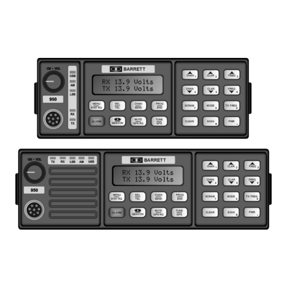
Barrett 900 series HF transceivers and receivers
BARRETT 930, 950 remote control ( trunk mount) HF transceivers
Head office:
Barrett Communications Pty Ltd
10 Port Kembla Drive, Bibra Lake WA 6163
P O Box 1214, Bibra Lake WA 6965
AUSTRALIA
Toll Free Tel: 1800 999 570
Tel: (61-8) 9 434 1700
Fax: (61-8) 9 418 6757
Technical manual
BARRETT 930, 950, 980 local control HF transceivers
BARRETT 950M HF transceiver module
BARRETT 950MR HF receiver
BARRETT 940 HF portable transceiver
©
BARRETT COMMUNICATIONS
© Barrett Communications
BCM90000/4
BARRETT 900 SERIES TRANSCEIVERS
European office
Barrett Europe Limited
19 Lenten Street
Alton, Hampshire
GU34 1HG
UNITED KINGDOM
Tel: (44) 1420 542254
Fax: (44) 1420 54337, P3
:
PAGE 1
Advertisement
Table of Contents


Need help?
Do you have a question about the 900 Series and is the answer not in the manual?
Questions and answers