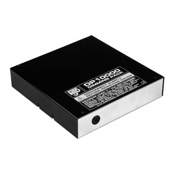
Summary of Contents for NJD Electronics NJ250 DP10000
- Page 1 NJ250 DP10000 4×10 A ANALOGUE DIMMING PACK • Individual 4-channel dimming • 2.3 kW power handling per channel • Terminal block input and output connectors • 0−10 V control inputs • Remote enable/disable Page 1...
-
Page 2: Product Safety
IMPORTANT Installer and Users please note: These instructions should be read carefully and left with the user of the product for future reference. BEFORE USE Inspect the product for any signs of damage. If the product is damaged, DO NOT use it, and contact your supplier immediately. PRODUCT SAFETY Do not use the appliance in locations where paint, petrol or other •... - Page 3 Connect the incoming mains supply (230 V) to the large terminal block using 6 mm cable: • Connect the incoming LIVE supply to the large terminal block labelled "LIVE". • Connect the incoming NEUTRAL supply to the large terminal block labelled "NEUTRAL"...
- Page 4 2300 W load may be connected to all four channels provided that the unit is operated so that all four channels are not switched on together at full power. • For a 32 A supply , the maximum total load is 7360 W which can be made up of: either: 1840 W watts on each of the four channels or: different loads on each channel so that the total does not exceed 7360 W (but not more than 2300 W on any one channel) or:...
- Page 5 If channels are to be used to their full capacity use 1mm wire. FUSING If connecting multiple loads to each output, reliability will be improved if each load is fitted with its own fuse, of an appropriate rating. In the case of a lamp failure, the lamp fuse will then blow, not the fuse in the power pack.
-
Page 6: Analogue Inputs
cables too close to sensitive audio circuits. Improved performance can be achieved as follows: • Each output channel should have its own separate neutral wire of the same length and thickness as the live wire • Each live output wire should be twisted together with its corresponding Neutral. -
Page 7: "Enable" Input
"ENABLE" INPUT The enable input allows the whole power pack to be enabled and disabled remotely. Note: If the enable input is not connected the power pack will not work. Permanently enabled If you require the DP10000 to be permanently enabled link the ENABLE input to the +10 V terminal. -
Page 8: Replacing Fuses
For longer cable runs, use 5-core screened cable, connecting the screen to the 0 V terminal. If interference still occurs (lamps flickering when mains nearby is switched on or off) then it may be helpful to connect the screen to mains earth. If the +15 V connection is not being used, then 5-core cable, or 4-core screened cable may be used. -
Page 9: Fault Finding
FAULT FINDING • All outputs permanently off - power indicator off Mains supply switched off • All outputs permanently off - power indicator on 10 V enable connection missing All low voltage inputs at 0 V Lighting controller not powered +15 V connection to lighting controller missing •... -
Page 10: Technical Specification
TECHNICAL SPECIFICATION Size: 215 x 205 x 45 mm Degree of protection: IP30 Weight: 2.1 kg Supply Voltage: 230 V ˜ 50 Hz Rated Insulation Voltage: 440 V AC Conditional Short Circuit current: I = 1.5 kA t (fuse rating) 300 A s per channel (Triac rating) -
Page 11: Disposal And Recycling
DISPOSAL AND RECYCLING You must not dispose of this appliance with domestic household waste. Most local authorities have specific collection system for appliances and disposal is free of charge to the end-user. When replacing an existing appliance with a similar new appliance your retailer may take the old appliance for disposal. -
Page 12: Service / Warranty
SERVICE WARRANTY Electrovision guarantees the product free from defects in materials and workmanship for a period of twelve months. Should this unit be operated under conditions other than those recommended, at voltages other than the voltage indicated on the unit, or any attempts made to service or modify the unit, then the warranty will be rendered void.

Need help?
Do you have a question about the NJ250 DP10000 and is the answer not in the manual?
Questions and answers