Advertisement
Quick Links
POWERFUL SOLUTIONS. GLOBAL FORCE.
L4182
Rev. B
Table of Contents:
Section
1.0 IMPORTANT RECEIVING INSTRUCTIONS . . . . . .1
2.0 SAFETY . . . . . . . . . . . . . . . . . . . . . . . . . . . . . . . . .1
INTERNATIONAL STANDARDS . . . . . . . . . . . . . . .2
4.0 PRODUCT DESCRIPTION . . . . . . . . . . . . . . . . . . .2
5.0 SETUP AND ASSEMBLY . . . . . . . . . . . . . . . . . . . .2
6.0 OPERATION . . . . . . . . . . . . . . . . . . . . . . . . . . . . . .4
7.0 TROUBLESHOOTING . . . . . . . . . . . . . . . . . . . . . .6
8.0 PRODUCT DATA . . . . . . . . . . . . . . . . . . . . . . . . . . .7
1.0 IMPORTANT RECEIVING INSTRUCTIONS
Visually inspect all components for shipping damage. Shipping
damage is not covered by warranty. If shipping damage is
found, notify carrier at once. The carrier is responsible for
all repair and replacement costs resulting from damage in
shipment.
2.0 SAFETY
2.1 Introduction
Read all instructions carefully. Follow all recommended safety
precautions to avoid personal injury as well as damage to the
product and/or damage to other property. Enerpac cannot be
responsible for any damage or injury from unsafe use, lack of
maintenance or incorrect operation. Do not remove warning
labels, tags, or decals. In the event any questions or concerns
arise, contact Enerpac or your local Enerpac distributor for
clarification.
If you have never been trained on high force tool safety,
consult your distributor or service center for a free Enerpac
safety course.
This manual follows a system of safety alert symbols, signal
words and safety messages to warn the user of specific
hazards. Failure to comply with these warnings could result
in death or serious personal injury, as well as damage to the
equipment or other property.
The Safety Alert Symbol appears throughout this
manual. It is used to alert you to potential physical
injury hazards. Pay close attention to Safety Alert
Symbols and obey all safety messages that follow this symbol
to avoid the possibility of death or serious personal injury.
Safety Alert Symbols are used in conjunction with certain
Signal Words that call attention to safety messages or property
damage messages and designate a degree or level of hazard
seriousness. The Signal Words used in this manual are
WARNING, CAUTION and NOTICE.
03/17
Page
Instruction Sheet
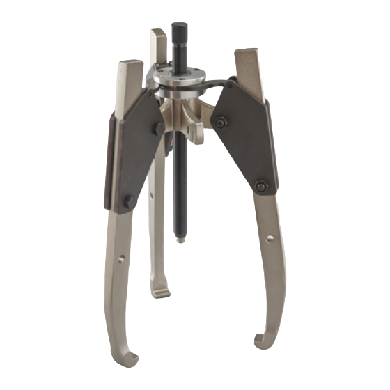
Mechanical Sync Grip Pullers
SGM-Series
Indicates a hazardous situation that, if not
WARNING
avoided, could result in death or serious
personal injury.
Indicates a hazardous situation that, if not
CAUTION
avoided, could result in minor or moderate
personal injury.
Indicates information considered important,
NOTICE
but not hazard related (e.g. messages
relating to property damage). Please note
that the Safety Alert Symbol will not be used
with this signal word.
2.2 Safety Precautions - Mechanical Sync Grip Pullers
Failure to observe and comply with the following
precautions could result in death or serious personal
injury. Property damage could also occur.
• Read and completely understand the safety precautions
and instructions in this manual before operating the puller or
preparing it for use.
• Wear appropriate personal protective equipment (PPE) such
as safety glasses and face shield. The operator must take
precautions against injury due to flying debris caused by
possible failure of the tool or workpiece.
• During operation, keep hands and fingers away from the
work area to avoid personal injury.
• Know the puller rated capacity before beginning any work.
• Do not use the puller in circumstances where a sudden
release of mechanical force could result in loss of balance,
causing damage or injury.
• Never attempt to pry the puller by inserting tools or other
objects between the jaws. This may cause center bolt
damage.
• It is impossible to predict the exact force needed for every
pulling situation. The amount of press fit and force of removal
can vary greatly between jobs. Set-up requirements along
with the size, shape and condition of the parts being pulled
1
WARNING
Advertisement

Subscribe to Our Youtube Channel
Related Manuals for Enerpac SGM Series


Summary of Contents for Enerpac SGM Series
-
Page 1: Table Of Contents
Failure to observe and comply with the following If you have never been trained on high force tool safety, precautions could result in death or serious personal consult your distributor or service center for a free Enerpac injury. Property damage could also occur. safety course. -
Page 2: Conformance To National And International Standards
• Immediately replace worn or damaged parts with genuine SGM20 can be assembled only in the three-jaw configuration. Enerpac parts. Enerpac parts are designed to fit properly See Figure 2 for jaw mounting details. and to withstand high loads. Non-Enerpac parts may break or cause the product to malfunction. - Page 3 Two-Jaw Configuration Three-Jaw Configuration (Models SGM01, SGM04, SGM07 and SGM10) (Models SGM01, SGM04, SGM07 and SGM10) Key: 1. Adjusting Rod with Square Head 2. Hex Nut 3. Plate 4. Jaw, Standard Length Jaw, Extended Reach (optional) 5. Capscrew 6. Strap 7.
-
Page 4: Operation
If there are any questions or concerns, contact the Enerpac Technical Service Department or your local Enerpac distributor. • Assemble the jaws on the puller body. Tighten mounting bolts and nuts. - Page 5 View A View B View D View C Jaws installed in the Minimal adjusting Acceptable adjusting Excessive adjusting highest mounting holes. rod protrusion. rod protrusion. rod protrusion. Figure 6, Jaw Mounting Positions and Adjusting Rod Height • For models SGM01, SGM04 and SGM07, if the end of the shaft is flat, install the point protector between the shaft end and the adjusting rod point.
-
Page 6: Troubleshooting
• Store the puller in a clean, dry and secure location. • If the puller requires repairs, refer to the Enerpac website for the repair parts sheet applicable to your puller model. -
Page 7: Product Data
8.0 PRODUCT DATA 8.1 General Specifications and Dimensions Refer to Section 8.2 for adjusting rod dimensions. Refer to Section 8.3 for jaw dimensions. Standard Length Jaws (all models) Extended Reach Long Jaws (Optional Accessory - SGM10 and SGM20 only) Capacity Maximum Reach Maximum Spread Weight... - Page 8 8.2 Specifications and Dimensions - Puller Adjusting Rod SGM01, SGM04, SGM07 SGM10, SGM20 Length Square Size Square Depth Thread Size Puller Model 4.88 0.47 0.55 M10 x 1.0 SGM01 6.97 0.63 0.79 M14 x 1.5 SGM04 SGM07 9.25 0.75 0.94 M18 x 1.5 12.64 0.87...
- Page 9 Notes:...
- Page 10 Notes:...
- Page 11 Notes:...
- Page 12 Enerpac Worldwide Locations e-mail: info@enerpac.com internet: www.enerpac.com Southeast Asia, Hong Kong Enerpac Integrated Solutions B.V. India Australia and New Zealand Actuant India Private Limited and Taiwan Spinelstraat 15, 7554 TS Hengelo Actuant Australia Ltd. Actuant Asia Pte Ltd. P.O. Box 421, 7550 AK Hengelo No.
Need help?
Do you have a question about the SGM Series and is the answer not in the manual?
Questions and answers