
Related Manuals for EUCHNER ECB-A-2K-A1-160397


Summary of Contents for EUCHNER ECB-A-2K-A1-160397
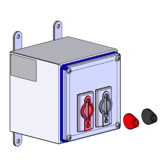
- Page 1 Operating Instructions Euchner Control Box ECB-A-2K-A1-160397 ECB-A-2K-A2-160398...
-
Page 2: Table Of Contents
Operating Instructions Euchner Control Box ECB-... Contents About this document ..................... 4 1.1. Scope ............................4 1.2. Target group ..........................4 1.3. Key to symbols ..........................4 1.4. Supplementary documents ......................4 Correct use ......................5 Description of the safety function ................7 3.1. - Page 3 System status table for the CES evaluation unit ........... 24 Technical data ....................25 11.1. Technical data for ECB-A-2K-A2-160398 ..................25 11.2. Technical data for ECB-A-2K-A1-160397 ..................26 Ordering information and accessories ..............27 12.1. Spare parts ..........................27 Inspection and service ..................27 Service ......................
-
Page 4: About This Document
Important! Always read all documents to gain a complete overview of safe installation, setup and use of the de- vice. The documents can be downloaded from www.euchner.com. For this purpose enter the doc. no. in the search box. (Translation of the original operating instructions) 2533580-02-03/20... -
Page 5: Correct Use
2. Correct use In combination with a control system, the Euchner Control Box allows dangerous machine movements to be performed as long as all valid unique, transponder-coded keys (CKS keys) are inserted. If at least one CKS key is removed during operation, the two safety contacts are switched off and a stop command is triggered. - Page 6 Operating Instructions Euchner Control Box ECB-... Important! Ì Information about safety switch CTP-LBI-AP-U-HA-AZ-SA-127798 is available in the operating in- structions (doc. no. 2136918). Ì If a data sheet is included with the product, the information on the data sheet applies.
-
Page 7: Description Of The Safety Function
Operating Instructions Euchner Control Box ECB-... 3. Description of the safety function The following applies to both ECB devices: Ì Reliable detection of a non-inserted CKS key. The uniquely coded CKS keys are tamper proof and safe to use: Ì... -
Page 8: Control Of Guard Locking For Safety Switch Ctp-Lbi-Ap
Ì Safety characteristics for the ECB-A1 device in combination with safety switch CTP-LBI-AP: category, Performance Level, (see chapter 11.2. Technical data for ECB-A-2K-A1-160397). 3.3. Control of guard locking for safety switch CTP-LBI-AP Control of guard locking in combination with the ECB device is not a safety function. -
Page 9: Exclusion Of Liability And Warranty
Prior to use, read the operating instructions and keep these in a safe place. Ensure the operating instructions are always available during mounting, setup and servicing. You should archive a printed copy of the operating instructions. You can download the operating instructions from www.euchner.com. 2533580-02-03/20 (Translation of the original operating instructions) -
Page 10: Function
Operating Instructions Euchner Control Box ECB-... 6. Function Important! The system can fulfill its safety function only if the users always carry their CKS keys with them when accessing the machine. When leaving the machine, they must ensure that there are no other persons in the machine. -
Page 11: Wiring Diagrams
Operating Instructions Euchner Control Box ECB-... 6.3. Wiring diagrams CKS key adapter, red CKS key adapter, black ECB-A-2K-A2-160398 Failsafe Figure 3: Wiring diagram for ECB-A2 device CKS key adapter, black CKS key adapter, red ECB-A-2K-A1-160397 CTP-LBI-AP-U-HA-AZ-SA-127798 Failsafe Figure 4: Wiring diagram for ECB-A1 device with safety switch CTP-LBI-AP... -
Page 12: Mounting
Operating Instructions Euchner Control Box ECB-... 7. Mounting CAUTION The ECB device or safety switch CTP-LBI-AP must not be bypassed (bridging of contacts), turned away, removed or otherwise rendered ineffective. Ì Observe EN ISO 14119:2013, section 7, for information about reducing the possibilities for by- passing an interlocking device. -
Page 13: Mounting The Housing Cover
Operating Instructions Euchner Control Box ECB-... 7.3. Mounting the housing cover 4x fixing screw Torx ISO 7380-2-M5X22 A2 T25 Tightening torque: 1.2 Nm Figure 7: Fastening the cover 7.4. Mounting safety switch CTP-LBI-AP NOTICE Mount safety switch CTP-LBI-AP according to the specifications in Operating Instructions Transpon- der-Coded Safety Switch CTP-LBI-AP Unicode/Multicode (see chapter 1.4. -
Page 14: Electrical Connection
Operating Instructions Euchner Control Box ECB-... 8. Electrical connection 8.1. Electrical connection of the ECB device WARNING In the event of a fault, loss of the safety function due to incorrect connection. Ì Monitoring outputs must not be used as safety outputs. -
Page 15: Safety In Case Of Faults
CAUTION Risk of damage to equipment or malfunctions as a result of incorrect connecting cables. Ì Use connection components and connecting cables from EUCHNER. NOTICE Observe the requirements for the connecting cables in Operating Instructions Transponder-Coded Safety Switch CTP-LBI-AP Unicode/Multicode (see chapter 1.4. Supplementary documents). -
Page 16: Cable Outlets When Using Angled Plugs
Operating Instructions Euchner Control Box ECB-... 8.7. Cable outlets when using angled plugs X2: connection for CTP-LBI-AP (only ECB-A1) X1: connection to PLC Euchner Control Box X2: connection for CTP-LBI-AP (only ECB-A1) X1: connection to PLC The following applies to the device installation orientation shown:... -
Page 17: Connector Assignment
Enable input for channel 2 X 1.7 Operating voltage, 0 V DC 0 V U Codiernase/ Coding lug X 1.8 n. c. Table 2: Pin assignment for ECB-A-2K-A1-160397 Connection to control system M12/8-pin Designation Function Control input of guard locking X 1.1 Male ange connector solenoid, 24 V DC... -
Page 18: Wiring Diagrams
Operating Instructions Euchner Control Box ECB-... 8.9. Wiring diagrams Figure 9: Wiring diagram for version ECB-A-2K-A2-160398 (Translation of the original operating instructions) 2533580-02-03/20... - Page 19 Operating Instructions Euchner Control Box ECB-... Figure 10: Wiring diagram for version ECB-A-2K-A1-160397, part 1 2533580-02-03/20 (Translation of the original operating instructions)
- Page 20 Operating Instructions Euchner Control Box ECB-... Figure 11: Wiring diagram for version ECB-A-2K-A1-160397, part 2 (Translation of the original operating instructions) 2533580-02-03/20...
-
Page 21: Setup
Operating Instructions Euchner Control Box ECB-... 9. Setup 9.1. Teaching-in a new CKS key Teach-in of CKS keys can be repeated any number of times. Observe the teach-in operation in accordance with section 9.1.2. Teach-in operation on the CES evaluation unit for this purpose. Faulty CKS keys can thus be replaced at any time. In the delivery state, the keys in the evaluation unit have already been taught-in. - Page 22 Operating Instructions Euchner Control Box ECB-... To trigger a teach-in operation, the user must perform the following actions in the stipulated order: 1. Prepare for teach-in operation - Switch off power supply U - Insert both keys into the key adapter. Observe the color assignment.
-
Page 23: Functional Check
Operating Instructions Euchner Control Box ECB-... 9.2. Functional check After a new CKS key has been taught-in, the safety function must be fully checked. Proceed as follows: WARNING Danger of fatal injury as a result of faults in installation and functional check. -
Page 24: System Status Table For The Ces Evaluation Unit
Operating Instructions Euchner Control Box ECB-... 10. System status table for the CES evaluation unit LED indicator Operating mode State STATE (green) (yellow) (red) Teach-in operation 1 Hz Teach-in operation Acknowledgment of completed teach-in operation Self-test, duration approx. 10 seconds, is performed after the application of the operating voltage 15 Hz... -
Page 25: Technical Data
Operating Instructions Euchner Control Box ECB-... 11. Technical data NOTICE If a data sheet is included with the product, the information on the data sheet applies. 11.1. Technical data for ECB-A-2K-A2-160398 Parameter Value Unit min. typ. max. Housing material Stainless steel 1.4301... -
Page 26: Technical Data For Ecb-A-2K-A1-160397
Operating Instructions Euchner Control Box ECB-... 11.2. Technical data for ECB-A-2K-A1-160397 Parameter Value Unit min. typ. max. Housing material Stainless steel 1.4301 Housing seal Silicone Safety class acc. to EN IEC 61558 Dimensions 160 x 160 x 150 Weight Approx. 2.5 Ambient temperature at U = 24 V DC... -
Page 27: Ordering Information And Accessories
12. Ordering information and accessories Tip! Suitable accessories, e.g. cables or assembly material, can be found at www.euchner.com. To order, enter the order number of your item in the search box and open the item view. Accessories that can be combined with the item are listed in “Accessories.”... -
Page 28: Declaration Of Conformity
Operating Instructions Euchner Control Box ECB-... 15. Declaration of conformity (Translation of the original operating instructions) 2533580-02-03/20... - Page 29 Operating Instructions Euchner Control Box ECB-... 2533580-02-03/20 (Translation of the original operating instructions)
- Page 30 Edition: 2533580-02-03/20 Title: Operating Instructions Euchner Control Box ECB-A-2K-A1-160397 ECB-A-2K-A2-160398 (Translation of the original operating instructions) Copyright: © EUCHNER GmbH + Co. KG, 03/2020 Subject to technical modifications; no responsibility is accept- ed for the accuracy of this information.
Need help?
Do you have a question about the ECB-A-2K-A1-160397 and is the answer not in the manual?
Questions and answers