
Related Manuals for nekos KATO RADIO 230V


Summary of Contents for nekos KATO RADIO 230V
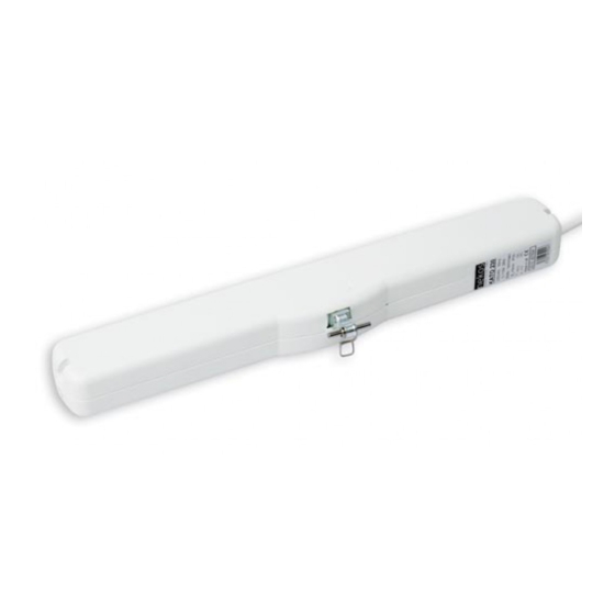
- Page 1 KATO RADIO HAIN OPERATED ACTUATOR ____ 300 N - T ORQUE RUCK 230V~ 50H LECTRICAL FEEDING INSTRUCTION MANUAL ENGLISH Page 1 Code 4420026 Edition no. 1 of 1 March 2006 Printed on 13/07/2006...
- Page 2 “presumed in conformity with directives” issued by the EU. nekos holds the technical file with all the documentation to show that our products have all been inspected to ensure compliance with directives conformity.
-
Page 3: Table Of Contents
CONTENTS ƒ ................... AFETY INDICATIONS ƒ ............ANUFACTURE AND REFER ENCE STANDARDS ƒ ....................CCESSORIES ƒ ....................ECHNICAL DATA ƒ .................. ABEL DATA AND MARKINGS ƒ ................... LECTRICAL SUPPLY ƒ... -
Page 4: Safety Indications
SAFETY INDICATIONS ATTENTION : PLEASE READ THE FOLLOWIN G SAFETY INDICATIONS CAREFULLY BEFORE ATTEMPTING INSTALLATION OF THIS APPLIANCE. THESE INDICATIONS WILL HELP TO AVOID CONTACT WITH ELECTRICAL CURRENT, INJURY AND OTHER ACCIDENTS. PLEASE KEEP THIS MANUAL FOR FUTURE CONSULTATION . The KATO RADIO chain operat ed actuator has been designed exclusively for moving windows. -
Page 5: Manufacture And Reference Standards
WARNING Risk of injury in the event that the window should fall on outward opening window frames. A safety system should be mounted onto the window to guard against falls. This system should be able to withstand at least three times the total weight of the window . -
Page 6: Technical Data
TECHNICAL DATA MODEL KATO RADIO 230V Pressure torque 300 N Traction torque 300 N Track runs (can be selected at any time) 100, 200, 300, 400 mm Voltage 230V~ 50 Hz Current consumption at nominal charge 0,115 A Charge absorbed at nominal load... -
Page 7: Remote Control Devices (Radio Operated Remote Control And Rain Sensor)
the feeder cable. The commands for are controlled by electrically OPEN CLOSE connected radio operated remot e control device on 433.92 MHz. REMOTE CONTROL DEVICES (Radio operated remote control and Rain sensor) The radio operated remote control device is the only device used for manually controlling the actuator. -
Page 8: Memorising Commands For The Radio Operated P2/Rrain Sensor
3. Press the button on the new radio control device to be assigned to the actuator. The activator pilot light will start to flash as soon as the key is released. 4. The pilot light should stop flashing. 5. Programming is now complete. All commands are ready for normal function. Memorising commands for the radio operated P2/R rain sensor The P2/R rain sensor commands all memorised motors within 60m out in the open area (walls, metal panels, iron cages etc all drastically reduce capacity). -
Page 9: Limit Switches At Opening
Limit switches at opening Four (4) positions can be selected for the limit switch of the outgoing chain. seen above, t o program, adjust t he two dip -switches no.3 and no.4. Programming is simple, immediate and can be carried out at any time by adjusting the two dip switches as indicated in the following table. -
Page 10: Assembly
ASSEMBLY These indications are intended for the attention of technicians and specialize d personnel. Basic job and safety techniques are therefore not included. All preparatory operations, assembly and electrical connections must be carried out by technical and specialized personnel to guarantee best performances and good function of the KATO RADIO chain operated actuator. -
Page 11: Assembly With Outward Opening Window
Assembly with outward opening window. Pencil in an “X” ove r the centre line of the window frame ( Fig. 2). Select the correct form of brackets ( Fig. 3). Attach the adhesive template to the window frame (fixed part) and line axis up with the centre line “X” Fig. -
Page 12: Assembly On Transom Window
Carry out a complete check of opening and closure of the window. Once the closure phase has been completed, check that the window frame is completely closed by checking the pressure on the weather strips . On re-entry the actuator limit switch functions automatically. -
Page 13: Assembly Of Actuator Onto Bay Or Outward Opening Window
Mount the actuator onto the brackets by inserting openings at each side onto correspondi ng pins on the brackets . Rotate the actuator 90°, bring the chain terminal up to the bracket and insert the pin into the opening on the bracket. -
Page 14: Electrical Connections
Mount the bracket for outward opening windows onto the moveable part of the frame in accordance with the markings indicated on the adhesive template . Complete assembly of the chain terminal with the rapid release hook inserted onto the provided pin Ø4x32 in median position (see fig. -
Page 15: Luminous Indications On Led
LUMINOUS INDICATIONS ON LED Before activating the actuator, famil iarise yourself with messages indicated by the red led opposite the lead. This will allow you to check that the machine is functioning properly or allow you to recognize possible irregularities. The led is only visible when the actuator has been turned on Status of LED Meaning... -
Page 16: Troubleshooting
TROUBLESHOOTING Please consult the following table for any eventual problems with function during installation or normal use : Problem Possible cause Solution Actuator doesn’t No electricity supply for Check state of safety work feeder. switch. Connecting cable not Check all electrical connected or wire not connections of gear motor. -
Page 17: Environmental Protection
ENVIRONMENTAL PROTECTION All materials used in the manufacture of this appliance are recyclable. We recommend tha t the device itself, and any accessories, packaging, etc. be sent to a centre for ecological recycling. WARRANTY The Manufacturer guarantees good machine function and undertakes to replace any defective parts due to bad quality materials or construction de fects in accordance with article 1490 of the Civil Code . -
Page 18: Pressure Calculation Formulas
Notes ………………………………………………………………………………………………………………………………………… ………………………………………………………………………………………………………………………………………… ………………………………………………………………………………………………………………………………………… ………………………………………………………………………………………………………………………………………… ………………………………………………………………………………………………………………………………………… ……………………………………………………………………………………………………………………………………… … ………………………………………………………………………………………………………………………………………… ………………………………………………………………………………………………………………………………………… ………………………………………………………………………………………………………………………………………… Page 18 Code 4420026 Edition no. 1 of 1 March 2006 Printed on 13/07/2006... -
Page 19: Declaration Of Conformity
36064 Mason Vicentino (VI) – ITALY Phone 0424 411011 – Fax 0424 411013 www.nekos.it info@nekos.it I, the undersigned, representative of the company NEKOS S.r.l., declares that the product defined below complies with the following directives : 73/23/CEE 89/336/CEE (Low tension d irective) - Page 20 NEKOS S.r.l. I - 36064 - MASON VICENTINO (VI) - Via Capitoni, 7/5 0424 411011 0424 411013 Phone (0039) Fax (0039) info@nekos.it - http://www.nekos.it Spett NEKOS S.r.l. Via Capitoni, 7/5 36064 MASON VICENTINO (VI) ITALY Page 20 Code 4420026 Edition no. 1 of 1...
Need help?
Do you have a question about the KATO RADIO 230V and is the answer not in the manual?
Questions and answers