
Subscribe to Our Youtube Channel
Related Manuals for Colormetrics P4500


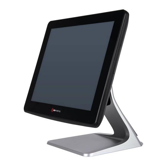
Summary of Contents for Colormetrics P4500
- Page 1 P4500 User Manual Version 1.0 Errors excepted; subject to change www.colormetrics.info...
-
Page 2: Copyright
COPYRIGHT SAFETY INSTRUCTIONS Copyright 2017 Colormetrics. All Rights Reserved. 1. Read these instructions carefully. Keep these instructions for future reference. 2. Please disconnect the equipment from AC outlet before cleaning. This manual, and the software and firmware described in it are copyrighted by their respective owners Don’t use liquid or spray detergents for cleaning. -
Page 3: Table Of Contents
MSR + iButton 6-4. USB 2nd Display 6-5. Configuration Utility of i-Button Reader MSR+RFID 6-6. VFD g. UPS Battery 7 BIOS/UTILITY SETUP 7-1. Advanced 7-2. Security 7-3. Power 7-4. Boot 7-5. Exit 8. LCD SURFACE CLEANING Colormetrics P4500 www.colormetrics.info www.colormetrics.info Colormetrics P4500... -
Page 4: System View 6 C
15" Display, VFD pole (optional) 2-2. Back View VFD Cover/8”/10.4” 2 Display (Optional) MSR/iButton/RFID HDD Cover (Optional) Please make sure the 19V DC is plugged in the right direction before plugging in DC jack. Colormetrics P4500 www.colormetrics.info www.colormetrics.info Colormetrics P4500... -
Page 5: Specification
2-3. Specification 2-4. Internal Layout M/B PCBA Model Ares755J Colormetrics P4500 Display Display Size 15" TFT LCD Resolution 1024 X 768 Brightness /Color 350 cd/㎡ , 16.7M colors Backlight Touch Panel Type 5 wire resistive or projected capacitive touch Processor CPU/ Chipset Intel®... -
Page 6: Pin Definition
USB D+ +3.3V +3.3V SPK1: Int. Speaker Pin Definition CN2: VFD connector Pin Definition Definition Definition Left Out + RTS# Left Out - DSR# Right Out- Right Out+ CTS# DTR# USB D- USB D+ Colormetrics P4500 www.colormetrics.info www.colormetrics.info Colormetrics P4500... -
Page 7: Rear I/O Interface
CN8: RJ11 (Cash Drawer) connector Pin Definition GREEN BLUE Definition C/D_OPEN# C/D Status +12V/+24V HSYNC VSYNC SPCLK CN6, CN7: 2-Layer USB3.0 pin Definition Definition Definition COM1, COM2, COM3: RJ45 Pin Definition Definition 5V/12V/Ring# DSR# DTR# RTS# CTS# Colormetrics P4500 www.colormetrics.info www.colormetrics.info Colormetrics P4500... -
Page 8: System Assembly & Disassembly
Slide the hard-drive bracket in an outward direction to remove it from the system Remove the 4 hard drive bracket screws Remove the 2 I/O board screws Remove the hard drive from the hard drive bracket Remove the 1 VFD screw Colormetrics P4500 www.colormetrics.info www.colormetrics.info Colormetrics P4500... -
Page 9: M.2 Ssd
Install the standoff to the location of M.2 2242 Remove the back cover Install the M.2 2242 SSD into the socket Install memory into the socket Push down on memory then fasten the screw 10. Push down on memory Colormetrics P4500 www.colormetrics.info www.colormetrics.info Colormetrics P4500... -
Page 10: Msr/Ibutton/Rfid
(note: display connector can only be connected to one device at a time) 3. Plug the MSR cable into the MSR connector 3. Install VFD with 2 screws / Install 8”/10.4” 2nd display with 2 screws 4. Reinstall the MSR cover with 2 screws Colormetrics P4500 www.colormetrics.info www.colormetrics.info Colormetrics P4500... - Page 11 Refer to page 66 to use the power menu to enable the 12V power and connect it to the 2nd 15‘‘ display. ☆ ☆ Refer to P.66 using the power menu to enable the 12V power to the COM port is connected to the 15” 2 display. Colormetrics P4500 www.colormetrics.info www.colormetrics.info Colormetrics P4500...
-
Page 12: 2D Barcode Scanner
1. Remove barcode scanner cover 2. Plug the barcode scanner cable into the barcode connector 2. Click “Next”. 3. Click “Next”. 3. Install the barcode scanner with 2 screws 4. Select “None”, Click “Next”. Colormetrics P4500 www.colormetrics.info www.colormetrics.info Colormetrics P4500... - Page 13 6. Select “Support Multi-Monitor System”, Click “Next”. 8. Click “Next”. 7. Click “Next”. 9. Click “Next”. Colormetrics P4500 www.colormetrics.info www.colormetrics.info Colormetrics P4500...
- Page 14 11. Would you do 4 point calibration now? Click “Yes”. (Resistive Touch only) 10. Select “Create a eGalaxTouch Utility shortcut on desktop”, Click “Next”. 12. Do 4 points aligrment to match display. 13. Calibration utility. Colormetrics P4500 www.colormetrics.info www.colormetrics.info Colormetrics P4500...
- Page 15 From Start/Programs, click MagSwipe folder Click MagSwipe Configuration Utility to launch the program. Select Reader Interface The reader to be configured should be connected. Select the corresponding connected reader interface and click the Continue button Colormetrics P4500 www.colormetrics.info www.colormetrics.info Colormetrics P4500...
- Page 16 Load From File The configuration data can be loaded into the configuration utility from a file that has been previously saved. Select this command, start a "File Open" dialog, which allows selection of the file. Colormetrics P4500 www.colormetrics.info www.colormetrics.info Colormetrics P4500...
- Page 17 The default setting will decoding card Close this dialog and return to the Home Menu Page. data with the card swiped in either the forward or the reverse direction. Colormetrics P4500 www.colormetrics.info www.colormetrics.info Colormetrics...
- Page 18 Choosing a longer inter-character delay causes the characters to be sent at a slower rate. data. These can be special characters for identifying a specific track. If the host system is not capable of receiving characters as fast as the reader can transmit, setting Colormetrics P4500 www.colormetrics.info www.colormetrics.info Colormetrics...
- Page 19 There are keyboard settings information on a magnetic stripe. MiniMag II will support following The reader can send the Start/End sentinel for a track, decoded without error. foreign language keyboard and function key output for PS/2 and USB HID Keyboard Interface. Colormetrics P4500 www.colormetrics.info www.colormetrics.info Colormetrics...
-
Page 20: Rfid
After you connect the device, the current reader configuration can be displayed by selecting this button. The configuration data of the connected reader will be displayed like in the example: Double-click to update driver. Colormetrics P4500 www.colormetrics.info www.colormetrics.info Colormetrics P4500... - Page 21 3. Select “Browse my computer for driver software.” 6. Install complete and then click “close” 4. Click Browse to select file called MP30U \Driver\FTDI\x64 And click Next. 7. Restart the computer 5. Install the driver Colormetrics P4500 www.colormetrics.info www.colormetrics.info Colormetrics P4500...
- Page 22 CD or a copy on hard drive. The GUI of software is shown in the picture below and ready to use. 2. Select “I have read and accept the license terms. And click Install.. Colormetrics P4500 www.colormetrics.info www.colormetrics.info Colormetrics...
- Page 23 The Windows User Account Control window opens (if enabled in the OS). 2. Click Yes. DisplayLink Core Software installs. The System Compatibility Check then runs. 4. Click Install (if the System Compatibility Check passes). Colormetrics P4500 www.colormetrics.info www.colormetrics.info Colormetrics P4500...
- Page 24 8. Reboot your SYSTEM to complete the installation. 6. Upon detection of a DisplayLink enabled device DisplayLink Graphics installs. ☆ ☆ Due to the Intel BayTrail J1900 CPU limitation, the DisplayLink driver can only be supported extend mode. Colormetrics P4500 www.colormetrics.info www.colormetrics.info Colormetrics P4500...
-
Page 25: Configuration Utility Of I-Button Reader
The steps below guide you how to install the Utility program. Insert the setup CD Run the Clientron iButton Utility.exe setup file that is located in the Software folder of CD Follow the wizard to complete the installation. 1. Setup Clientron iButton Utility.exe software Colormetrics P4500 www.colormetrics.info www.colormetrics.info Colormetrics P4500... - Page 26 The utility program will detect the connected reader. If detected, all the input text boxes will be enabled. If the reader has not been connected to PC yet, please connect the reader and then click Refresh to get connected. Colormetrics P4500 www.colormetrics.info www.colormetrics.info Colormetrics P4500...
-
Page 27: Vfd
4. “Get Setting from VFD” button to get all the settings from Clientron and it’ll refresh the “VFDset.exe” software. 5. Select “Character Type”/ “Command Mode”/ “Baud Rate Select”/ “pass thru Mode”. 3. To execute “VFDset.exe” for setting up communication between software and VFD module. Colormetrics P4500 www.colormetrics.info www.colormetrics.info Colormetrics P4500... - Page 28 5. Select “Character Type”/ “Command Mode”/ “Baud Rate Select”/ “pass thru Mode”. the all Message characters on AP. b. Hex mode Hex mode can define the character from 0x20h to0xFFh,the range 0x80~0XFF which depends on the code page table. Colormetrics P4500 www.colormetrics.info www.colormetrics.info Colormetrics P4500...
- Page 29 “Download O.K! Please restart!” message popped up. Please restart display for enable new setting 9. Click “Save” button To save user’s setting in file; for example, as shown in the picture below to save file name as “GOODLUCK” file set for Welcome Message. Colormetrics P4500 www.colormetrics.info www.colormetrics.info Colormetrics P4500...
-
Page 30: Bios/Utility Setup
Windows OS, these items are automatically updated whenever you make changes to the Windows Date and Time Properties utility. WARNING! Setting the wrong values in the sections below may cause the system to malfunction. Make sure that the settings made are compatible with the hardware. Colormetrics P4500 www.colormetrics.info www.colormetrics.info Colormetrics P4500... -
Page 31: Advanced
7-1-1. Boot Configuration 7-1. Advanced Use the Boot Configuration menu to select power-on state for Numlock. Use the Advanced menu to configure the system for basic operation through the following sub-menus: Colormetrics P4500 www.colormetrics.info www.colormetrics.info Colormetrics P4500... - Page 32 Video Configuration 7-1-2. Audio Configuration Use the Video Configuration menu to read Video configuration information and configure the Video Use the Audio Configuration menu to read Audio configuration information and configure the Audio settings settings Colormetrics P4500 www.colormetrics.info www.colormetrics.info Colormetrics P4500...
-
Page 33: Security
7-2. Security 7-1-4. SATA Configuration Use the Security menu to install or change the password Use the SATA Configuration menu to read SATA configuration information and configure the SATA settings Colormetrics P4500 www.colormetrics.info www.colormetrics.info Colormetrics P4500... -
Page 34: Power
Enable or disable system power on automatically after AC power restored Wake on LAN Enable or disable system wake by onboard LAN chip COM Voltage This item allows you to select off, 5V or 12V powered COM Colormetrics P4500 www.colormetrics.info www.colormetrics.info Colormetrics P4500... -
Page 35: Exit
3. What types of cleaners are acceptable? ☆ Water ☆ Vinegar (mixed with water) ☆ Isopropyl Alcohol NOTICE: The following cleaners are unacceptable: Acetone Ethyl alcohol Ethyl acid Ammonia Methyl chloride Colormetrics P4500 www.colormetrics.info www.colormetrics.info Colormetrics P4500...
Need help?
Do you have a question about the P4500 and is the answer not in the manual?
Questions and answers