True blue power TI250 Series Installation Manual And Operating Instructions
Static electrical power inverter
Hide thumbs
Also See for TI250 Series:
- Installation and operating instructions manual (15 pages) ,
- Installation manual and operating instructions (15 pages)
Table of Contents
Advertisement
Advertisement
Table of Contents

Related Manuals for True blue power TI250 Series

Summary of Contents for True blue power TI250 Series
- Page 1 Revision J • May 4, 2020...
- Page 2 This manual provides information intended for use by persons who, in accordance with current regulatory requirements, are qualified to install this equipment. If further information is required, please contact: True Blue Power c/o Mid-Continent Instrument Co., Inc. Attn: Customer Service Dept.
-
Page 3: Table Of Contents
TABLE OF CONTENTS SECTION 1 GENERAL DESCRIPTION 4 1.1 INTRODUCTION 4 1.2 TECHNICAL SPECIFICATIONS 5 SECTION 2 PRE-INSTALLATION CONSIDERATIONS 6 2.1 COOLING 6 2.2 EQUIPMENT LOCATION 6 2.3 ROUTING OF CABLES 6 2.4 LIMITATIONS 6 2.5 MODIFICATION 7 SECTION 3 INSTALLATION 8 ... - Page 4 REVISION HISTORY Date Detail Approved 12/10/2013 Initial release 02/11/2014 Revised Technical Specifications 05/27/2014 Revised Section 3.3.1, Wire Gauge Selection 01/02/2015 Added TI254 and TI256 models 05/11/2015 Added -4 Configuration 06/16/2015 Updated -4 Configuration specifications Update connector Pinout Table to agree with the input 01/06/2017 voltage in the Specification Table.
-
Page 5: Section 1 General Description
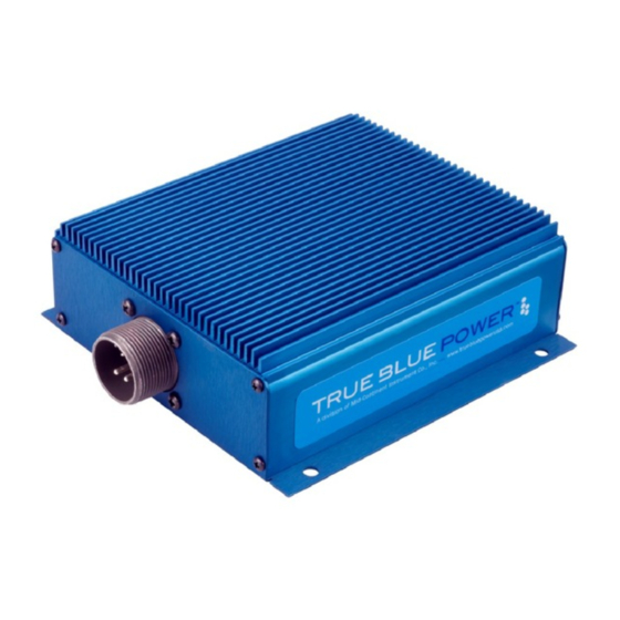
The TI250 Series has the same connector of legacy designs plus ground fault interrupter protection. The rugged extrusion that houses the unit is designed to help dissipate heat and provide mechanical strength against vibration or other possibilities of damage. -
Page 6: Technical Specifications
TECHNICAL SPECIFICATIONS Electrical Attributes Model Model Model TI256 Model TI256 TI250 TI254 Input Voltage 28VDC nominal; 20-36VDC 18-36VDC Input Current (full load) 10 amps nominal; 15 amps max 20A max Input Current (no load) 150 milliamps Input Current (ON/OFF = OFF) 50 milliamps Recommended Circuit Breaker 15 amps... -
Page 7: Section 2 Pre-Installation Considerations
SECTION 2 PRE-INSTALLATION CONSIDERATIONS COOLING The TI250 Series does not require external cooling or contain internal active cooling. Cooling of the unit occurs exclusively through passive conduction through the base or radiated cooling across the metal case. Additional cooling can be realized through convective effects of the environment (exposure to free moving air). -
Page 8: Modification
MODIFICATION This product has a nameplate that identifies the manufacturer, part number, description, certification(s) and technical specifications of the unit. It also includes the “MOD” or modification number representing notable changes in the hardware design of the unit. Modification (MOD) 0 is the initial release of the product and is identified on the nameplate by the lack of marking on the MOD numbers 1 through 9 (i.e. -
Page 9: Section 3 Installation
This section contains interconnect diagrams, mounting dimensions and other information pertaining to the installation of the TI250 Series Static Inverter. After installation of cabling and before installation of the equipment, ensure that power is applied only to the pins specified in the interconnect diagram. - Page 10 INVERTER AC OUPUT: AC Return – Used for powering devices where terrestrial/utility power designations are used, pin C can be connected as “Neutral”. AC Output – Used for powering devices where terrestrial/utility power designations are used, pin B can be connected as “Line” or “Hot”. Note: Use of a circuit breaker on the AC output is optional.
- Page 11 Connector Pinout 20-36VDC Input 20-36VDC Input 115VAC Output 115VAC Output AC Return AC Return DC Return DC Return Remote On/Off Fault Indication Fault Indication Remote On/Off Remote Return Reserved 20-36VDC Input DC Return 115VAC Output AC Return Figure 3.3 AC Return Remote On/Off DC Return 18-36VDC Input...
- Page 12 TI250 6430250-1 28VDC FAULT 1.5K 1W INVERTER ENABLE 110VAC OUTLETS CASE ATTACHED -OR- NOT ATTACHED TO AIRFRAME Figure 3.4B: Typical TI250 Aircraft Wiring Installation TI254 6430250-2 28VDC FAULT AIRCRAFT MONITORING 1.5K 1W SYSTEM INVERTER ALWAYS ENABLED 2.5A FIXED AIRCRAFT EQUIPMENT CASE ATTACHED -OR- NOT ATTACHED TO AIRFRAME Figure 3.4C: Typical Installation (400 Hz;...
- Page 13 TI250 6430250-1 28VDC AIRCRAFT CABIN ACCESSORIES SYSTEM 2.5A 110VAC OUTLET Optional Breaker CASE ATTACHED -OR- NOT ATTACHED TO AIRFRAME Figure 3.4D: Fully-Integrated Multi-Inverter Aircraft Cabin System TI256 6430250-3 28VDC FAULT AIRCRAFT MONITORING 1.5K 1W SYSTEM 26V 400Hz EQUIPMENT 2.5A 115V 400Hz EQUIPMENT CASE ATTACHED -OR- NOT ATTACHED TO AIRFRAME...
-
Page 14: Mounting
Refer to Section 2: Pre-Installation Considerations in regards to equipment location. The TI250 Series Static Inverter is designed for base mounting only. Four #10 mounting holes should be provided in the aircraft in accordance with Figure 3.5. Secure the unit with four #10 pan head Phillips screws, or equivalent. -
Page 15: Installation Caution
INSTALLATION CAUTION Do not connect the output of the TI250 Series Static Inverter to the output of any other inverter or damage will result. Under no circumstance allow the output of the inverter to be connected to ground utility AC power or damage will result. If more than 250 watts of power is required for an installation, a higher power inverter model such as the 500 watt Mid-Continent MD50 should be selected. -
Page 16: Section 4 Operation
SECTION 4 OPERATION ELECTRICAL PERFORMANCE The TI250 Series Static Inverter converts a direct current (DC) voltage input to a regulated VAC output; the output is controlled to an established frequency and represents a pure sine wave with minimal distortion. See Table 4.1 specific output and frequency. - Page 17 Short Circuit And Over-Current The TI250 Series Static Inverter is capable of surviving a short circuit or over-current event without permanent damage or effect to long-term reliability. The unit can provide over its rated power output up to 375 watts for over 30 minutes (until over-temperature shutdown occurs).
-
Page 18: Section 5 Conformance
No periodic scheduled maintenance or calibration is necessary for continued airworthiness of the TI250 Series Static Inverter. If the unit fails to perform to specifications, the unit must be removed and serviced by Mid-Continent Instruments and Avionics or their authorized designee.
Need help?
Do you have a question about the TI250 Series and is the answer not in the manual?
Questions and answers