Table of Contents
Advertisement
Quick Links
Advertisement
Table of Contents

Related Manuals for PR electronics 5105B


Summary of Contents for PR electronics 5105B
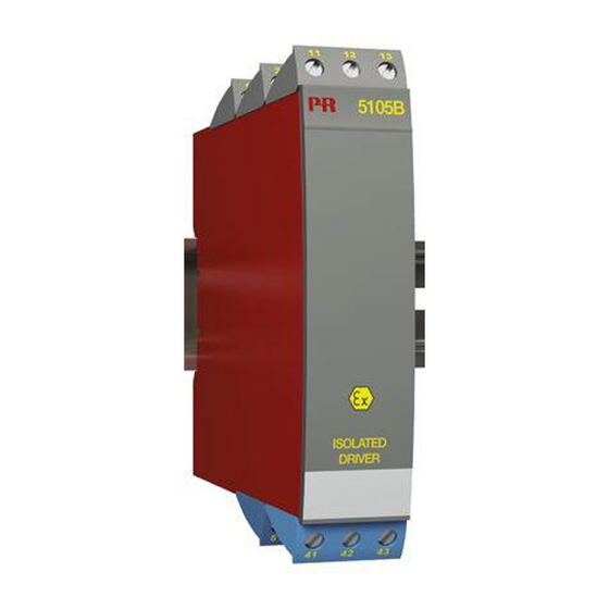
- Page 1 PERFORMANCE MADE SMARTER Product manual 5105B Ex-isolated driver T E M P E R AT U R E I . S . I N T E R FA C E S CO M M U N I C AT I O N I N T E R FA C E S...
- Page 2 6 Product Pillars to meet your every need Individually outstanding, unrivalled in combination With our innovative, patented technologies, we make signal conditioning smarter and simpler. Our portfolio is composed of six product areas, where we offer a wide range of analog and digital devices covering over a thousand applications in industrial and factory automation.
-
Page 3: Table Of Contents
Ex-isolated driver 5105B Table of contents Warning .................... -
Page 4: Warning
General mounting, wire connection and disconnection. Troubleshooting the device. VOLTAGE Repair of the device and replacement of circuit breakers must be done by PR electronics A/S only. Warning SYSTEM 5000 must be mounted on a DIN rail according to DIN 46277. -
Page 5: Safety Instructions
Should there be any doubt as to the correct handling of the device, please contact your local distributor or, alternatively, PR electronics A/S www.prelectronics.com Mounting and connection of the device should comply with national legislation for mounting of electric materials, i.e. wire cross section, protective fuse, and location. -
Page 6: How To Demount System 5000
How to demount system 5000 First, remember to demount the connectors with hazardous voltages. Picture 1: By lifting the bottom lock, the device is detached from the DIN rail. Picture 2: Then, by lifting the upper lock and pulling the front plate simultaneously the PCB is removed. - Page 7 Applications I / P Converter Input Supply Display Input Supply Current, mA Input Supply Voltage Input Supply 5105BV105-UK...
-
Page 8: Application
1 : 1 or signal conversion of analogue current / voltage signals. Technical characteristics • The 20 factory-calibrated measurement ranges in the 5105B can be selected by the internal DIP-switches without the need for a recalibration. Special measurement ranges can be delivered. •... -
Page 9: Order
Order Type Input Output Channels 5105B 0…20 mA Special Single 4…20 mA 0…20 mA Double 0…10 V 4…20 mA 2…10 V 0…1 V Special 0.2…1 V 0…10 V 2…10 V Electrical specifications Environmental conditions Operating temperature ....... . -20°C to +60°C Calibration temperature. - Page 10 Accuracy, the greater of the general and basic values: General values Input type Absolute accuracy Temperature coefficient ≤ ±0.1% of span ≤ ±0.01% of span / °C Basic values Input type Basic accuracy Temperature coefficient ≤ ±16 μA ≤ ±1.6 μA / °C Volt ≤...
- Page 11 Observed authority requirements EMC..........2014/30/EU LVD .
-
Page 12: Dip-Switch Programming
DIP-switch programming Factory-calibrated standard ranges Input: (channel 2, DP 3 and DP 4) Output: 0...20 mA 4...20 mA 0...10 V 2...10 V D P 1 D P 2 D P 1 D P 2 D P 1 D P 2 D P 1 D P 2 0...20 mA... -
Page 13: Connections
Connections Supply: Inputs: Current Voltage Current Voltage Outputs: Current Voltage Current Voltage 5105BV105-UK... -
Page 14: Block Diagram
24...230 VAC & 24...250 VDC Supply 1 2 3 4 Input +,V 0...20 2M Ω Output +, I and V Input +,I 10 Ω Input - 10 V 5105B Channel 1 Output -, I and V 5105B Channel 2 CH 2 5105BV105-UK... -
Page 15: Ul Control Drawing 5105Qu01
The sum of capacitance and inductance of cable and intrinsic safe equipment must be less or equal to Ca and La Voltage or current output 5105B 5105B Associated apparatus parameters Terminals 41 to 43 Terminals 51 to 53 Voc (Uo) 28 V Isc (Io) 93 mA 0.65 W... - Page 16 We are near you, all over the world Our trusted red boxes are supported wherever you are All our devices are backed by expert service and a 5-year business with a global reach. This means that we are warranty. With each product you purchase, you receive always nearby and know your local markets well.
- Page 17 Benefit today from PERFORMANCE MADE SMARTER PR electronics is the leading technology company specialized in making industrial process control safer, more reliable and more efficient. Since 1974, we have been dedicated to perfecting our core competence of innovating high precision technology with low power consumption.
Need help?
Do you have a question about the 5105B and is the answer not in the manual?
Questions and answers