Advertisement
Available languages
Available languages
Quick Links
Displays
Programmable displays with a wide se-
lection of inputs and outputs for display of temperature,
volume and weight, etc. Feature linearisation, scaling,
and difference measurement functions for programming
via PReset software.
Ex interfaces
Interfaces
for
analogue
®
signals as well as HART
signals between sensors / I/P
converters / frequency signals and control systems in Ex
zone 0, 1 & 2 and for some modules in zone 20, 21 & 22.
Isolation
Galvanic isolators for analogue and digital
signals as well as HART
®
signals. A wide product range
with both loop-powered and universal isolators featuring
linearisation, inversion, and scaling of output signals.
Temperature
A wide selection of transmitters for DIN
form B mounting and DIN rail modules with analogue
and digital bus communication ranging from application-
specifi c to universal transmitters.
Universal
PC or front programmable modules with
universal options for input, output and supply. This range
offers a number of advanced features such as process
calibration, linearisation and auto-diagnosis.
and
digital
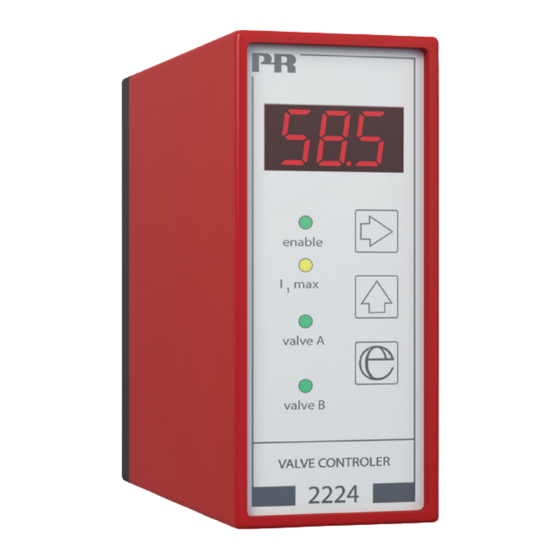
2 2 2 4
V a l v e C o n t r o l l e r
N o . 2 2 2 4 V 1 0 3 - I N ( 0 8 4 0 )
F r o m s e r . n o . 0 6 0 2 2 3 0 0 1
S I G N A L S T H E B E S T
Side 1
DK
Page 19
UK
Page 37
FR
Seite 55
DE
Advertisement
Chapters

Related Manuals for PR electronics 2224


Summary of Contents for PR electronics 2224
- Page 1 Displays Programmable displays with a wide se- lection of inputs and outputs for display of temperature, volume and weight, etc. Feature linearisation, scaling, and difference measurement functions for programming via PReset software. Ex interfaces Interfaces analogue digital ® signals as well as HART signals between sensors / I/P converters / frequency signals and control systems in Ex zone 0, 1 &...
-
Page 2: Table Of Contents
VENTILSTYRING TYPE 2224 INDHOLDSFORTEGNELSE EF-overensstemmelseserklæring ........Adskillelse af SYSTEM 2200 ..........Anvendelse ................. Teknisk karakteristik ............Indgang ................Udgang ................Bestillingsskema..............Elektriske specifikationer ........... Blokdiagram ............... Timing diagram ..............DIP-switchprogrammering ..........Fortrådningsdiagrammer for joystick / potentiometerindgang ........... 10 Fortrådningsdiagrammer for DC strømindgang ....11 Fortrådningsdiagrammer for DC spændingsindgang .. -
Page 3: Ef-Overensstemmelseserklæring
EF-OVERENSSTEMMELSESERKLÆRING ADSKILLELSE AF SYSTEM 2200 Som producent erklærer Billede 1. PR electronics A/S Modulets bagplade frigøres fra huset ved hjælp af en skruetrækker. Lerbakken 10 DK-8410 Rønde hermed at følgende produkt: Type: 2224 Navn: Ventilstyring er i overensstemmelse med følgende direktiver og standarder: EMC-direktivet 2004/1086/EF og senere tilføjelser... -
Page 4: Anvendelse
• Er yderst velegnet til joystick-regulering af A/B bevægelse. Teknisk karakteristik: • Ventilstyringen 2224 er en mikroprocessor-styret enhed, som indeholder ram- pefunktioner til blød start og stop og springfunktioner således, at dødbånd undgås ved start og ved skift mellem A & B ventil. -
Page 5: Elektriske Specifikationer
Elektriske specifikationer: BLOKDIAGRAM Specifikationsområde: -20°C til +60°C Fælles specifikationer: Forsyningsspænding ........9,6...14,4 eller 19,2...28,8 VDC Egetforbrug ..........2 W / 24 V 1,8 W / 12 V Kommunikation ........... Frontprogrammering Opdateringstid..........30 ms Temperaturkoefficient ........0,01% / °C Linearitetsfejl ..........0,2% EMC-immunitetspåvirkning ...... -
Page 6: Timing Diagram
TIMING-DIAGRAM Signal Funktion Funktion indgang: pos.: DP 1 DP 1 0...20 mA 2 - 3 1 2 3 4 5 6 7 8 1 2 3 4 5 6 7 8 DP 1 4...20 mA Ingen funktion 2 - 3 1 2 3 4 5 6 7 8 DP 1 DP 1... -
Page 7: Fortrådningsdiagrammer For Joystick / Potentiometerindgang
FORTRÅDNINGSDIAGRAMMER FOR FORTRÅDNINGSDIAGRAMMER FOR JOYSTICK- / POTENTIOMETERINDGANG DC STRØMINDGANG Dobbelt ventilstyring via Dobbelt ventilstyring med +/- 10 VDC referencespænding. 0...20 mA indgangssignal. DIP-switchprogrammering: DIP-switchprogrammering: Funktion 2. Funktion 1 eller Funktion 2. Dobblet ventilstyring via Enkelt ventilstyring med + 10 VDC referencespænding. 4...20 mA indgangssignal. -
Page 8: Fortrådningsdiagrammer For Dc Spændingsindgang
FORTRÅDNINGSDIAGRAMMER FOR DC TEKNISK BESKRIVELSE SPÆNDINGSINDGANG • For at hindre at programmering kan ske under drift, er der indlagt to sik- kerhedsforanstaltninger. Det korrekte password (030) skal indtastes i menuen Dobbelt ventilstyring med [PAS], og udgangen må ikke give signal (displayet skal vise 000). Dette opnås 0...1 VDC indgangssignal. -
Page 10: Rutediagram
0.0. Normal tilstand - displayet viser udgangsværdi i procent af I ventil . PROGRAMMERING / BETJENING Displayet går til denne tilstand ved power ON, eller hvis ingen taster har AF TRYKKNAPPER været aktiveret i en periode på 2 minutter. 1.0 VAL - Indtastning af password. 1.1 PAS - Programmeringsadgang. -
Page 11: Indstilles I % Af Indgangsspan
5.0 PAR - Indstilling af parametre for udgang. VALVE CONTROLLER 5.1 REV - Valg af direkte / inverteret udgang. 0 = direkte, 1 = inverteret. TYPE 2224 Lovlige valg er 0 eller 1. 5.2 DOD - Indstilling af dødbånd for f.eks. joystick. Indstilles i % af indgangsspan. -
Page 12: Ec Declaration Of Conformity
EC DECLARATION OF CONFORMITY HOW TO DISMANTLE SYSTEM 2200 As manufacturer Picture 1. PR electronics A/S The back panel of the module is detached from the housing by way Lerbakken 10 of a screwdriver. DK-8410 Rønde hereby declares that the following product:... -
Page 13: Applications
• Is highly suitable for joystick regulation of A/B movements. Technical characteristics: • The 2224 Valve Controller is a microprocessor-based unit containing ramp functions for soft start and stop and jump functions thus avoiding deadband at start and changes between A & B valves. -
Page 14: Electrical Specifications
Electrical specifications: BLOCK DIAGRAM Specifications range: -20°C to +60°C Common specifications: Supply voltage ..........9.6...14.4 or 19.2...28.8 VDC Internal consumption ........2 W / 24 V 1.8 W / 12 V Communication ........... Front-programmable Updating time ..........30 ms Temperature coefficient ....... 0.01%/°C Linearity error .......... -
Page 15: Timing Diagram
TIMING DIAGRAM Signal Function Function input: pos.: DP 1 DP 1 0...20 mA 2 - 3 1 2 3 4 5 6 7 8 1 2 3 4 5 6 7 8 DP 1 4...20 mA No function 2 - 3 1 2 3 4 5 6 7 8 DP 1 DP 1... -
Page 16: Wiring Diagrams For Joystick / Potentiometer Input
WIRING DIAGRAMS FOR JOYSTICK / WIRING DIAGRAMS FOR POTENTIOMETER INPUT DC CURRENT INPUT Double valve control (A/B Double valve control (A/B valves) from +/-10 VDC valves) from a 4...20 mA reference supply. input signal. DIP-switch programming: DIP-switch programming: Function 2. Function 1 or Function 2. -
Page 17: Wiring Diagrams For Dc Voltage Input
+Vsupply on terminal 3. input signal. DIP-switch programming: • The 2224 Valve Controller can be controlled by a joystick / potentiometer Function 1 or using the internal +10 V and -10 V supply, or a process current / voltage sig- Function 2. -
Page 19: Routing Diagram
0.0. DEFAULT - Output percentage value of I is displayed. PROGRAMMING / OPERATING valve At power ON, or if no keys have been activated for a period of 2 minutes, THE FUNCTION KEYS the display returns to default. DOCUMENTATION FOR ROUTING DIAGRAM 1.0 VAL - Enter password. - Page 20 REGULATEUR DE VANNE 5.1 REV - Selection of direct / inverted output. 0 = direct, 1 = inverted. TYPE 2224 Valid selections are 0 or 1. 5.2 DOD - Setting of deadband for e.g. joystick. The parameter is entered as a percentage of the input span.
-
Page 21: Déclaration De Conformité Ce
Lerbakken 10 DK-8410 Rønde déclare que le produit suivant : Type : 2224 Nom : Regulateur de vanne correspond aux directives et normes suivantes : La directive CEM (EMC) 2004/108/CE et les modifications subséquentes Figure 2. -
Page 22: Applications
• Les circuits de mesure et régulation interne assurent au courant moyen de ne • Le régulateur de vanne 2224 est idéal pour la régulation de mouvements A/B pas excéder la valeur entrée : Ivanne. -
Page 23: Spécifications Électriques
Spécifications électriques : SCHÉMA DE PRINCIPE Plage des spécifications : -20°C à +60°C Spécifications communes : Tension d’alimentation ........ 9,6...14,4 ou 19,2...28,8 Vcc Consommation interne ........ 2 W / 24 V 1,8 W / 12 V Configuration ..........Programmable en face avant Temps de réponse ........ -
Page 24: Diagramme De Fonctionnement
DIAGRAMME DE FONCTIONNEMENT Signal Fonction Fonction d’entrée : pos. : DP 1 DP 1 0...20 mA 2 - 3 1 2 3 4 5 6 7 8 1 2 3 4 5 6 7 8 DP 1 4...20 mA Pas de fonction 2 - 3 1 2 3 4 5 6 7 8 DP 1... - Page 25 DIAGRAMMS DE RACCORDEMENT POUR DIAGRAMMES DE RACCORDEMENT POUR ENTRÉE MANETTE / POTENTIOMÈTRE L’ENTRÉE COURANT CC Contrôle double par tension Contrôle double par un signal de référence de +/- 10 Vcc. d’entrée de 4...20 mA. Configuration des commuta- Configuration des commuta- teurs : teurs : Fonction 2.
-
Page 26: Description Technique
Cela est obtenu en coupant le + de la tension d’alimentation de la borne 3. Configuration des commuta- teurs : • Le PR-2224 peut être contrôlé par une manette / un potentiomètre en Fonction 1 ou utilisant l’alimentation interne de +10 V ou ±10 V, ou un signal courant / Fonction 2. -
Page 28: Diagramme De Programmation
0.0. Mise sous tension - La valeur de la I vanne . PROGRAMMATION / UTILISATION L’affichage prend cet état lors de la mise sous tension ou si aucune touche DES TOUCHES DE FONCTION n’est actionnée pendant deux minutes. DOCUMENTATION POUR LE DIAGRAMME DE PROGRAMMATION 1.0 VAL - Accès à... -
Page 29: Stant
VENTILSTEUERUNG 5.1 REV - Sélection de la sortie directe / inverse. 0 = Directe, 1 = Inverse. TYP 2224 Les sélections possibles sont 0 ou 1. 5.2 DOD - Réglage de la bande morte pour par ex. la manette. La valeur est réglée en % de la gamme d’entrée. -
Page 30: Eg-Konformitätserklärung
EG-KONFORMITÄTSERKLÄRUNG ZERLEGUNG DES SYSTEMS 2200 Als Hersteller bescheinigt Abbildung 1. PR electronics A/S Die hintere Abdeckplatte des Moduls wird vom Gehäuse mit Hilfe eines Lerbakken 10 Schraubendrehers gelöst. DK-8410 Rønde hiermit für das folgende Produkt: Typ: 2224 Name: Ventilsteuerung die Konformität mit folgenden Richtlinien und Normen: EMV Richtlinien 2004/108/EG und nachfolgende Änderungen... -
Page 31: Anwendung
Technische Merkmale: • Der interne Mess- und Regelkreislauf sichert, das der Mittelstrom nie den • Die Ventilsteuerung 2224 ist eine mikroprozessorgesteuerte Einheit, die eingetasteten Wert des I Ventils übersteigt. Rampenfunktionen für einen weichen Start und Stopp enthält, weiterhin •... -
Page 32: Elektrische Daten
Elektrische Daten: BLOCKDIAGRAMM Spezifikationsbereich: -20°C bis +60°C Gemeinsame Daten: Versorgungsspannung ......... 9,6...14,4 oder 21,2...28,8 VDC Eigenverbrauch ........... 2 W / 24 V 1,8 W / 12 V Kommunikation ........... Frontprogrammierung Aufdatierungszeit......... 30 ms. Temperaturkoeffizient ........0,01% / °C Linearitätsfehler ........... 0,2% Immunitätseinwirkung ......... -
Page 33: Zeitdiagramm
ZEITDIAGRAMM Signal- Funktion Funktion Eingang: Pos.: DP 1 DP 1 0...20 mA 2 - 3 1 2 3 4 5 6 7 8 1 2 3 4 5 6 7 8 DP 1 4...20 mA Keine Funktion 2 - 3 1 2 3 4 5 6 7 8 DP 1 DP 1... -
Page 34: Verdrahtungsdiagramme Für Joystick/Potentiometereingang
VERDRAHTUNGSDIAGRAMME FÜR VERDRAHTUNGSDIAGRAMME FÜR DC- JOYSTICK- / POTENTIOMETEREINGANG STROMEINGANG Zweifache Ventilsteuerung Zweifache Ventilsteuerung mit durch eine +/- 10 VDC einem 4...20 mA Eingangssignal. Referenzspannung DIP-Schalterprogrammierung: DIP-Schalterprogrammierung: Funktion 1 oder Funktion 2. Funktion 2. Zweifache Ventilsteuerung Einfache Ventilsteuerung mit durch eine + 10 VDC einem 4...20 mA Eingangssignal. -
Page 35: Verdrahtungsdiagramme Für Dc Spannungseingang
VERDRAHTUNGSDIAGRAMME FÜR DC- TECHNISCHE BESCHREIBUNG SPANNUNGSEINGANG • Zwei Sicherheitsmaßnahmen sind eingelegen um Programmierung während des Betriebs zu verhindern. Das korrekte Passwort (030) muss ins Menü [PAS] einge Zweifache Ventilsteuerung mit geben werden und der Ausgang muss kein Signal abgeben (das Display muss einem Eingangssignal von 0...1 000 zeigen). -
Page 37: Schleifendiagramm
0.0. Normalzustand - Das Display zeigt den Ausgangswert von I Ventil in PROGRAMMIERUNG / BEDIENUNG Prozent an. DER DRUCKTASTEN Das Display geht in diesen Zustand beim Einschalten der Spannung, oder wenn keine Taste innerhalb einer Periode von 2 Minuten aktiviert DOKUMENTATION ZUM SCHLEIFENDIAGRAMM worden ist. -
Page 38: Stant
5.0 PAR - Parametereinstellung für den Ausgang. 5.1 REV - Wahl von direktem / invertiertem Ausgang. 0 = direkt, 1 = invertiert. Zulässige Wahlmöglichkeiten 0 oder 1. 5.2 DOD -Einstellung des Todbandes für z.B. den Joystick. Die Einstellung geschieht in % vom Eingangsbereich. Zulässige Wahlmöglichkeiten 0...99,9%. - Page 39 Subsidiaries PR electronics A/S tilbyder et bredt program af analoge og digi- France tale signalbehandlingsmoduler til industriel automation. Vores PR electronics Sarl Zac du Chêne, Activillage sales@prelectronics.fr kompetenceområder omfatter: Isolation, Displays, Ex-interfaces, 4, allée des Sorbiers tel. +33 (0) 4 72 14 06 07 Temperatur samt Universal-moduler.
Need help?
Do you have a question about the 2224 and is the answer not in the manual?
Questions and answers