Table of Contents
Advertisement
Quick Links
Advertisement
Table of Contents

Related Manuals for PR electronics 2224


Summary of Contents for PR electronics 2224
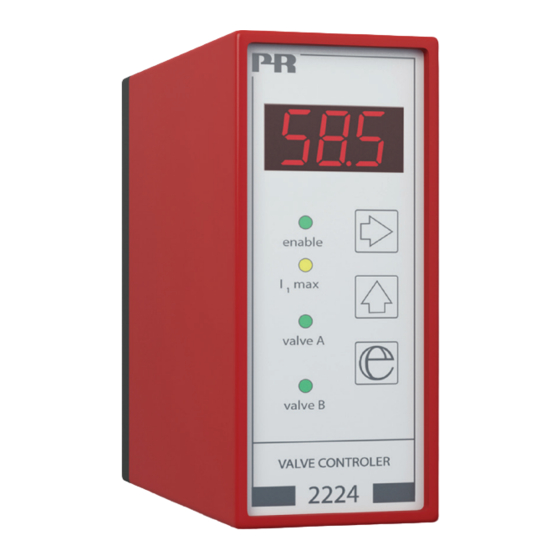
- Page 1 PERFORMANCE MADE SMARTER Product Manual 2224 Valve controller T E M P E R AT U R E I . S . I N T E R FA C E S CO M M U N I C AT I O N I N T E R FA C E S...
- Page 2 6 Product Pillars to meet your every need Individually outstanding, unrivalled in combination With our innovative, patented technologies, we make signal conditioning smarter and simpler. Our portfolio is composed of six product areas, where we offer a wide range of analog and digital devices covering over a thousand applications in industrial and factory automation.
-
Page 3: Table Of Contents
Valve controller 2224 Contents How to dismantle system 2200 ................ -
Page 4: How To Dismantle System 2200
How to dismantle system 2200 Picture 1: The back panel of the device is detached from the housing by way of a screwdriver. Picture 2: After this, the back panel can be pulled out together with the PCB, but please notice the position of the PCB as there is a number of different positions in the house. -
Page 5: Applications
Is highly suitable for joystick regulation of A/B movements. Technical characteristics • The 2224 Valve Controller is a microprocessor-based unit containing ramp functions for soft start and stop and jump functions thus avoiding deadband at start and changes between A & B valves. •... -
Page 6: Order
Order Type Input Supply Option 2224 0...20 mA 12 V Single valve (A) 4...20 mA 24 V Double valve (A/B) 0...1 V 0.2...1 V 0...10 V 2...10 V ±10 V potentiometer 0...10 V potentiometer Electrical specifications Environmental conditions Operating temperature ....... . -20°C to +60°C Humidity. -
Page 7: Block Diagram
Observed authority requirements EMC..........2014/30/EU EAC . -
Page 8: Timing Diagram
Timing diagram Input, function 2 100% deadband Output, mean current Imax Imax 100% jump Imax value ramp 100% Imax Digital input, +V sup. DIP-switch programming Input signal and function are chosen via the DIP-switch setting. Function 1: Single and double valve control. By double valve control, A valve is chosen by applying +Vsupply to terminal 2. Function 2: Double valve control with automatic change between A and B valves (no signal on terminal 2). - Page 9 Signal Function Function input: pos.: D P 1 D P 1 0...20 mA 2 - 3 O f f O f f 1 2 3 4 5 6 7 8 1 2 3 4 5 6 7 8 D P 1 4...20 mA No function 2 - 3...
-
Page 10: Wiring Diagrams For Joystick / Potentiometer Input
Wiring diagrams for joystick / potentiometer input Double valve control (A/B valves) from +/-10 VDC supply + +10 V reference supply. DIP-switch programming: supply gnd - 10 V Function 2. B valve + Input + 10 K A valve + +V supply = I max 1 DP 1 +V supply = enable... -
Page 11: Wiring Diagrams For Dc Current Input
Wiring diagrams for DC current input Double valve control (A/B valves) from a 4...20 mA supply + input signal. DIP-switch programming: +V sup. = A supply gnd Function 1 or Function 2. A or B valve B valve + Input + 50 ohm A valve + Input -... -
Page 12: Wiring Diagrams For Dc Voltage Input
Wiring diagrams for DC voltage input Double valve control (A/B valves) from a 0...1 VDC supply + input signal. DIP-switch programming: +V sup. = A supply gnd Function 1 or Function 2. A or B valve B valve + Input + A valve + Input - +V supply = I max 1... -
Page 13: Technical Description
• The 2224 Valve Controller can be controlled by a joystick / potentiometer using the internal +10 V and -10 V supply, or a process current / voltage signal. For process signals the differential amplifier (DP1 switch 6 off) will reduce disturbances from noisy signals. -
Page 14: Routing Diagram
Routing diagram Programming At power ON, or if no keys have been activated for a Memory Power ON period of 2 minutes, the display returns to main menu 0.0. Main menu 0.0. Go to entry menu / Leave menu without changes. Next digit or point. -
Page 15: Configuration / Operating The Function Keys
Configuration / operating the function keys Documentation for routing diagram General The configuration is menu-controlled. The main menus are numbered in level 0 (x.0), and the submenus are numbered in level 1 (x.1 to x.4). Each submenu has an accompanying entry menu. The menus are structured in such a way that the menus most frequently used are closer to the default menu 0.0. - Page 16 4.0 RAN - Setting of ramp parameters 4.1 ON - Selection of on/off ramp 1 = ramp enable, 0 = ramp disable. Valid selections are 0 or 1. 4.2 UP - Setting of ramp time up The ramp time is set in seconds. Valid selections are 0...10 s.
- Page 17 We are near you, all over the world Our trusted red boxes are supported wherever you are All our devices are backed by expert service and a 5-year with a global reach. This means that we are always nearby warranty. With each product you purchase, you receive and know your local markets well.
- Page 18 Benefit today from PERFORMANCE MADE SMARTER PR electronics is the leading technology company specialized in making industrial process control safer, more reliable and more efficient. Since 1974, we have been dedicated to perfecting our core competence of innovating high precision technology with low power consumption.
Need help?
Do you have a question about the 2224 and is the answer not in the manual?
Questions and answers