Table of Contents
Advertisement
Quick Links
Advertisement
Table of Contents

Related Manuals for ITC COMPACT V 2000CP


Summary of Contents for ITC COMPACT V 2000CP
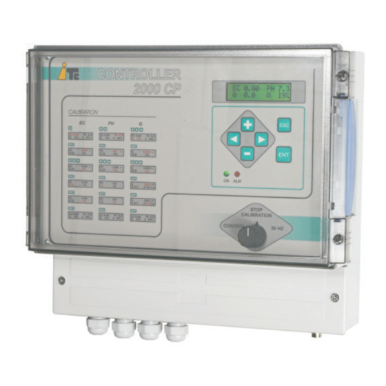
- Page 1 COMPACT V EC, PH, ORP, FLOW CONTROLLER ENGLISH...
- Page 2 SAFETY RULES SAFETY RULES To avoid personal or enviromental damages and to guarantee a proper To avoid personal or enviromental damages and to guarantee a proper operation of the equipment, the staff in charge of the installation, set up and operation of the equipment, the staff in charge of the installation, set up and maintenance of the equipment must follow the instructions of this manual, maintenance of the equipment must follow the instructions of this manual,...
-
Page 3: Table Of Contents
INDEX INDEX 1.- GENERAL DESCRIPTION 1.- GENERAL DESCRIPTION 1.1 General description 1.1 General description 1.2 Description of front part 1.2 Description of front part 1.3 Descriotion ofl display 1.3 Descriotion ofl display 2.-CARRIAGE AND MAINTENANCE 2.-CARRIAGE AND MAINTENANCE 3.- TECHNICAL FEATURES 3.- TECHNICAL FEATURES 4.-FUNCTIONEMENT 4.-FUNCTIONEMENT... -
Page 4: General Description 1.-General Description
1.-GENERAL DESCRIPTION 1.-GENERAL DESCRIPTION COMPACT V allows to control the injection of the heads of a dosing pump COMPACT V allows to control the injection of the heads of a dosing pump through a frequency variator. through a frequency variator. Injection control through PROPORTIONALITY Injection control through PROPORTIONALITY Control of the injection of a dosing pump through a frequency variator, in order to... -
Page 5: Description Of Front Part 05
4.-DESCRIPTION OF FRONT PART 4.-DESCRIPTION OF FRONT PART DISPLAY DISPLAY EC 1.50 EC 1.50 PH 6.3 PH 6.3 Q 25.3 Q 25.3 KEY TO INCREASE KEY TO INCREASE ESCAPE KEY TO ESCAPE KEY TO VALUE VALUE GET OUT FROM GET OUT FROM MENU WITHOUT MENU WITHOUT CONFIRM... -
Page 6: Carriage And Maintenance 2.-Carriage And Maintenance
2.- CARRIAGE AND MAINTENANCE 2.- CARRIAGE AND MAINTENANCE The original packing is prepared so that carriage and storing of the product do not The original packing is prepared so that carriage and storing of the product do not cause any damage to the product, as long as this is done far from heat sources and cause any damage to the product, as long as this is done far from heat sources and in dry, ventilated spaces. -
Page 7: Functionement 4.-Functionement
EC: 1.40 mS EC: 1.40 mS Value of the conductivity buffer supplied by ITC. If another buffer is to be used, the Value of the conductivity buffer supplied by ITC. If another buffer is to be used, the value of the new buffer will have to be introduced. - Page 8 EXT: 4-20 mA EXT: 4-20 mA Selection of outside outlet, 4-20 mA or 0-10V. Selection of outside outlet, 4-20 mA or 0-10V. T Q = 0 : 5 s T Q = 0 : 5 s Minimum time to activate the Q=0 alarm (zero flow), in case it is activated. Minimum time to activate the Q=0 alarm (zero flow), in case it is activated.
-
Page 9: 4.2 Gauging
4.2 GAUGING 4.2 GAUGING GAUGING THE CONDUCTIVITY PROBE GAUGING THE CONDUCTIVITY PROBE PH N.N PH N.N PUSH PUSH WILL APPEAR WILL APPEAR EC N.NN EC N.NN EC N.NN EC N.NN Flashing Flashing PUSH PUSH WILL APPEAR WILL APPEAR N.NN N.NN N.NN N.NN Flashing... -
Page 10: Gauging Of The Ph / Orp (Rx) Probe - Gauging Of The Ph / Orp (Rx) Probe 10
GAUGING OF THE PH / RX PROBE GAUGING OF THE PH / RX PROBE PH N.N PH N.N PUSH PUSH WILL APPEAR WILL APPEAR EC N.NN EC N.NN PH N.N PH N.N Flashing Flashing PUSH PUSH WILL APPEAR WILL APPEAR N.NN N.NN N.NN... -
Page 11: Gauging Of Flowmeter And The Injection Flow - Gauging Of Flowmeter And The Injection Flow 11
GAUGING OF FLOWMETER AND THE GAUGING OF FLOWMETER AND THE INJECTION FLOW INJECTION FLOW PH N.N PH N.N PUSH PUSH WILL APPEAR WILL APPEAR EC N.NN EC N.NN Q N.N Q N.N Flashing Flashing N.NN% N.NN% N.NN% N.NN% PUSH PUSH WILL APPEAR WILL APPEAR Flashing... - Page 12 4.3 SET POINTS AND REGULATION 4.3 SET POINTS AND REGULATION CONDUCTIVITY SET POINT AND REGULATION CONDUCTIVITY SET POINT AND REGULATION PH N.N PH N.N EC N.NN EC N.NN PUSH PUSH WILL APPEAR WILL APPEAR EC N.NN EC N.NN Flashing Flashing N.NN N.NN N.NN...
-
Page 13: Ph / Orp (Rx) Setpoint / Regulation - Ph / Orp (Rx) Setpoint / Regulation 13
PH / ORP (RX) SET POINT AND REGULATION PH / ORP (RX) SET POINT AND REGULATION PH N.N PH N.N EC N.NN EC N.NN PUSH PUSH WILL APPEAR WILL APPEAR PH. N.N PH. N.N Flashing Flashing N.NN N.NN PUSH PUSH WILL APPEAR WILL APPEAR Flashing... -
Page 14: Porportionality Value / Regulation - Porportionality Value / Regulation 14
PROPOTIONALITY VALUE AND REGULATION PROPOTIONALITY VALUE AND REGULATION Q. N.N Q. N.N PH N.N PH N.N EC N.NN EC N.NN PUSH PUSH WILL APPEAR WILL APPEAR Flashing Flashing N.NN% N.NN% N.NN% N.NN% PUSH PUSH WILL APPEAR WILL APPEAR Flashing Flashing TO INCREASE OR DECREASE THE PROPORTIONAL VALUE TO INCREASE OR DECREASE THE PROPORTIONAL VALUE PUSH... -
Page 15: Alarms Conductivity Alarms Conductivity Alarms
4.4 ALARMS 4.4 ALARMS CONDUCTIVITY ALARMS CONDUCTIVITY ALARMS PH N.N PH N.N PUSH PUSH WILL APPEAR WILL APPEAR EC N.NN EC N.NN EC N.NN EC N.NN Flashing Flashing PUSH PUSH WILL APPEAR WILL APPEAR N.NN N.NN N.NN N.NN Flashing Flashing PUSH PUSH WILL APPEAR... -
Page 16: Ph / Orp (Rx) Alarms - Ph / Orp (Rx) Alarms 16
PH / RX ALARMS PH / RX ALARMS PH N.N PH N.N PUSH PUSH WILL APPEAR WILL APPEAR EC N.NN EC N.NN PH N.N PH N.N Flashing Flashing PUSH PUSH WILL APPEAR WILL APPEAR Flashing Flashing N.NN N.NN PUSH PUSH WILL APPEAR WILL APPEAR Flashing... -
Page 17: Flow Alarms Flow Alarms
FLOW ALARMS FLOW ALARMS PH N.N PH N.N EC N.NN EC N.NN PH N.N PH N.N PUSH PUSH WILL APPEAR WILL APPEAR Flashing Flashing N.NN% N.NN% N.NN % N.NN % PUSH PUSH WILL APPEAR WILL APPEAR Flashing Flashing PUSH PUSH WILL APPEAR WILL APPEAR N.NN... -
Page 18: Choosing Automatic Or Hand Regulation 18
4.5 CHOOSING AUTOMATIC (A) OR MANUAL (M) 4.5 CHOOSING AUTOMATIC (A) OR MANUAL (M) REGULATION REGULATION PH N.N PH N.N EC N.NN EC N.NN PUSH PUSH WILL APPEAR WILL APPEAR PUSH PUSH TO CHOOSE : TO CHOOSE : A: AUTOMATIC REGULATION A: AUTOMATIC REGULATION M: MANUAL REGULATION M: MANUAL REGULATION... -
Page 19: Selection Of Visualition Of The Outgoing Signal 19
4.7 SELECTION OF VISUALIZATION OF THE 4.7 SELECTION OF VISUALIZATION OF THE OUTGOING SIGNAL OUTGOING SIGNAL 4 - 20 mA: INVERTER SIGNAL 4 - 20 mA: INVERTER SIGNAL (% : only COMPACT S) (% : only COMPACT S) PH N.N PH N.N EC N.NN EC N.NN... -
Page 20: Installation 5.- Installation 20
5 . - I N S TA L L AT I O N To install this pump it is advisable to choose places protected from water, away from heat sources and with air renewal. INVERTER COMPACT V KASUGA CHARGE STOP KVFH 3PH-200V-0.75kW DANGER... - Page 21 FLOWMETER Instant flowmeter. To set it up follow the instructions contained in the relevant Handbook. C O N N E C T O R C L A M P F O R FLOWMETER 1“ ¼ Connector clamp with flowmeter adapter. PH / RX ELECTRODE To set it up follow instructions contained in the relevant Handbook.
- Page 22 MULTIFERTIC MULTIFERTIC To set it up follow the instructions To set it up follow the instructions contained in the relevant contained in the relevant Handbook, keeping in mind that Handbook, keeping in mind that the frequency variator will work the frequency variator will work as a motor protection.
- Page 23 WIRING DIAGRAM WIRING DIAGRAM FLOW FLOW 220 V AC 220 V AC VENT VENT ALARM ALARM (24 V AC OUTPUT) (24 V AC OUTPUT) IRRIGATION IRRIGATION TIMER TIMER (24V AC INPUT) (24V AC INPUT) 4-20mA 4-20mA (U,V,W, (U,V,W, 220 V AC-III 220 V AC-III 220 V AC - I 220 V AC - I...
-
Page 24: Start Up 6.-Start Up
6.-START UP 6.-START UP INJECTION CONTROL THROUGH PROPORCIONALITY INJECTION CONTROL THROUGH PROPORCIONALITY WATER WATER INJECTION INJECTION FLOWMETER FLOWMETER COMPACT V COMPACT V FLOW FLOW FLOW FLOW USUARIO USUARIO NOMINAL NOMINAL PUMP PUMP PROPORTION PROPORTION FLOW FLOW (a 50 Hz) (a 50 Hz) The maximum water flow together with the maximum flow of the dosing The maximum water flow together with the maximum flow of the dosing Pump (see table of the flow increases through to work to 60 Hz, on page 10),... - Page 25 COMPACT V IN COMPACT V IN FIX ALL THE COMPONENTS (chapter 5 pag 20), leaving out of the pipe the FIX ALL THE COMPONENTS (chapter 5 pag 20), leaving out of the pipe the conductivity and PH / RX detector. conductivity and PH / RX detector.
- Page 26 INJECTION CONTROL THROUGH CONDUCTIVITY INJECTION CONTROL THROUGH CONDUCTIVITY EC ELECTRODE EC ELECTRODE INJECTION INJECTION INVERTER INVERTER COMPACT V COMPACT V FLOW FLOW USER USER SET POINT SET POINT The regulation of the injection flw is made through a PI control. This sort of The regulation of the injection flw is made through a PI control.
- Page 27 COMPACT V IN COMPACT V IN • • FIX ALL THE COMPONENTS (chapter 5 pag 20), leaving out of the pipe the FIX ALL THE COMPONENTS (chapter 5 pag 20), leaving out of the pipe the conductivity and PH / RX detector. conductivity and PH / RX detector.
- Page 28 COMPACT V IN COMPACT V IN • • THE DOSING PUMP WILL START UP. OBSERVE THE DELAY TIME OF THE DOSING PUMP WILL START UP. OBSERVE THE DELAY TIME OF THE INSTALLATION: The time which goes between starting the dosing THE INSTALLATION: The time which goes between starting the dosing pump and the change in the conductivity reading produced by this injection.
-
Page 29: Maintenance 7.- Maintenance
7.- MAINTENANCE 7.- MAINTENANCE A 9 C 1 A 9 C 1 33516 33516 33155 33155 S. PH PH2 S. PH PH2 CONTROL CONTROL AL. PH/EC AL. PH/EC ALM. Q=0 ALM. Q=0 +4.20 mA +4.20 mA 33605 33605 34601(soft) 34601(soft) 33162 33162 42350... - Page 30 List of parts List of parts CODE CODE DESCRIPTION DESCRIPTION UNIT UNIT 33-036 33-036 Relay board Con2-v6 assembly Relay board Con2-v6 assembly 33153 33153 Cable ser c + ( c 6p) nº 1 Cable ser c + ( c 6p) nº 1 33154 33154 Cable flow 270mm c+( c3p )
- Page 31 EC CONFORMITY DECLARATION EC CONFORMITY DECLARATION I.T.C S.L.. I.T.C S.L.. Mar Adriàtic, 1 Vallès, 26 Polígono Torre del Rector Polígono Industrial Can Bernades-Subirà 08130 Santa Perpètua de Mogoda 08130 Santa Perpètua de Mogoda Declares that all models COMPACT V products, identified by a serial number and Declares that all models COMPACT V products, identified by a serial number and year of manufacture, strictly fulfill low voltages directives 73/23/CE and year of manufacture, strictly fulfill low voltages directives 73/23/CE and...
- Page 32 Original manual Ed:30/04/2019 - EN C/ Vallès, 26 Pol. Ind. Can Bernades - Subirà P.O. Box 60 08130 Santa Perpètua de Mogoda BARCELONA Tel. 93 544 30 40 Fax 93 544 31 61 e-mail: itc@itc.es www.itc-dosing-pumps.com...
Need help?
Do you have a question about the COMPACT V 2000CP and is the answer not in the manual?
Questions and answers