Advertisement
Quick Links
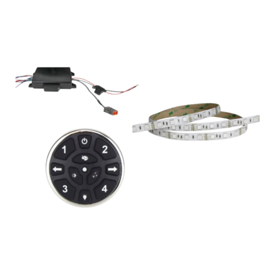
PARTS / TOOLS NEEDED:
VersiControl RGB
Smart System
Safety Instructions
• Disconnect power before installing, adding or changing any component.
• To avoid a hazard to children, account for all parts and destroy all packing materials.
• Do not install any luminaire assembly closer than 6" from any combustible materials.
• Positive (+) outputs require a fuse if the attached wire leads are not rated to handle the max current.
• This device complies with part 15 of the FCC rules. Operation is subject to the following two conditions:
- This device may not cause harmful interference
- This device must accept any interferences received, including interference that may cause undesired operation
1.
INSTALL: Determine the installation location for your control module. Make sure to consider the size of the module (7.5"L x 5"W x 1.5"H)
when determining your location. Note, it will require room for access and for wiring. Screw the controller in place using four M5 stainless
steel screws (not provided) sized appropriately for the substrate material used. Make sure when mounted, that the Bluetooth antenna is
not obstructed by metal objects.
7.5"
2.
CONNECT CONTROL PAD: If using the control pad (optional), insert
the connector on the control pad into the connector on the
module. Refer to control pad installation instructions for more
detailed information.
Phone: 616-396-1355 • www.itc-us.com • sales@itc-us.com • DOC#: 710-00025 Rev F • 09/20/17
VersiControl RGBW Smart System Install Instructions
Smart Pad
RGB Lighting
(Optional)
(Varies)
Bluetooth Antenna
For warranty information please visit www.itc-us.com
3030 Corporate Grove Dr. • Hudsonville • MI • 49426
(Part #'s: 22500-RGB-XX & 22500-RGBW-XX)
Mounting Screws x 4
(not provided)
5"
3.
ZONE WIRE CONNECTIONS: Refer to the diagram below for refer-
ence when wiring the system in step 4. Note, there can be 16 or
20 zone wires coming out of the controller. Each wire has been
individually placed on the grommet of the assembly.
ZONE 2
+
+
ZONE 1
Butt Splices
(not provided)
ZONE 4
R
G
B
W
W
B
G
R
W
B
G
R
R
G
B
W
ZONE 3
Power Drill
1.5"
+
+
Advertisement

Related Manuals for ITC VersiControl 22500-RGBW Series


Summary of Contents for ITC VersiControl 22500-RGBW Series
- Page 1 ZONE 2 ZONE 4 ZONE 1 ZONE 3 For warranty information please visit www.itc-us.com 3030 Corporate Grove Dr. • Hudsonville • MI • 49426 Phone: 616-396-1355 • www.itc-us.com • sales@itc-us.com • DOC#: 710-00025 Rev F • 09/20/17...
- Page 2 CAN (-) Zone 4 - (Max 8A) *Mating Connector: Deutsch DTM04-6P (+) White/Red Green 22500-RGBW-XX Blue White 3030 Corporate Grove Dr. • Hudsonville • MI • 49426 Phone: 616-396-1355 • www.itc-us.com • sales@itc-us.com • DOC#: 710-00025 Rev F • 09/20/17...
- Page 3 By default, only zones one and two are turned off. There is no effect on zones three and four. You can adjust which zones are turned off via a CAN interface display system. 3030 Corporate Grove Dr. • Hudsonville • MI • 49426 Phone: 616-396-1355 • www.itc-us.com • sales@itc-us.com • DOC#: 710-00025 Rev F • 09/20/17...
Need help?
Do you have a question about the VersiControl 22500-RGBW Series and is the answer not in the manual?
Questions and answers
I have a 22500-rgbw I have touch screen I hit the on Button display shows on and then kicks off right away have no lights
If the ITC 22500-RGBW Series touchscreen turns on and then immediately turns off with no lights, it could be due to the disable line (pin 4 of the 6-pin Deutsch connector) receiving input voltage (5–24 volts). When this happens, zones one and two are turned off by default. If no other zones are configured or active, no lights will turn on.
This answer is automatically generated