
Subscribe to Our Youtube Channel
Related Manuals for Bubble Boat Bubble No 1


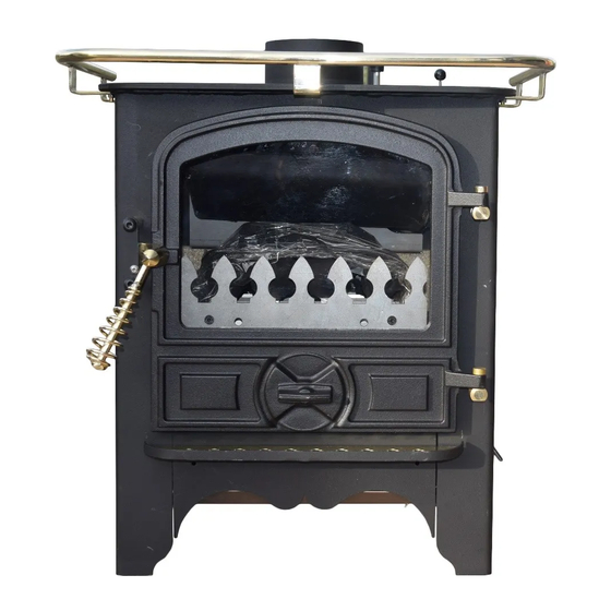
Summary of Contents for Bubble Boat Bubble No 1
- Page 1 INSTALLATION & GENERAL INSTRUCTIONS Silent Simplicity just for you! MARINE OIL STOVES © ISSUE 15 @ 22-06-18 www.harworthheating.co.uk...
- Page 2 7. DISTANCES FROM NON COMBUSTIBLES (APPLIANCES) 8. DISTANCES FROM COMBUSTIBLES (FLUE PIPES) 9. ILLUSTRATIONS FIG 1. STOVE DISTANCE FROM COMBUSTIBLES FIG 2 BUBBLE MK1 FABRICATED DECK FLANGE LAYOUT FIG 3 TYPICAL OIL FEED LAYOUT FIG 4 TYPICAL PUMBING LAYOUTS 10. STOVE DIMENSIONS...
- Page 3 APPLIANCES. with air in a vaporizing pot located in the bottom of the stove. Boat Bubble No 1 AND HALF POD, Dry Small and Large Boiler Appliances Once the appliance has been ignited, oil goes into the pot at a steady and controlled rate via a gravity feed Boat Bubble No 2 Dry Small and Large Boiler which is metered by the OIL CONTROL VALVE;...
- Page 4 Where applicable, the door glass may require light There are unusually strong cross winds. • cleaning occasionally depending upon the continuous If down draughting occurs turn the appliance off running time of the stove. until the winds subside and do not attempt to re- Appliances must be securely bolted down to resist ignite the appliance until it has completely cooled impact or collision and must be level in both directions.
- Page 5 Bubble appliances must not be fitted if the Any combustible materials within the specified maximum angle of trim exceeds 0.75 deg forward distances from the appliances must be protected by a to aft or port to starboard.
- Page 6 If the bubble stove is fitted up to the first bulkhead should be fitted. it will be necessary to fit the isolation valve outside the cabin or saloon of the boat.
- Page 7 There are two different types of burner fitted to The sensing phial may be visible through the bottom of Bubble appliances. the fender, to mask it, paint it with matt black paint The FB style burner fitted to the B1 Half Pod, B1 available from our sales desk.
- Page 8 Lighting into the base of the Pot Turn the oil off. On the first light up you may find this option better, Cut a small piece of firelighter and stab it onto the as it is possible to see the oil trickle in to the pot spike.
- Page 9 To see a bubble stove running correctly see the following link https://www.youtube.com/watch?v=UqdQLFp3HkQ &...
- Page 10 THE HIGH FIRE SETTING WILL HAVE TO BE OMMISSIONING THE HIGH AND LOW FIRE OCOMEF ADJUSTED IN LINE WITH THE AVAILABLE URNERS Corner Stove, Corner Pod and Back Cabin Cooker. GENNERATED CHIMNEY VACUUM IE Note that Back cabin Cookers are pre commissioned THE FLUE PIPE MUST BE A MINIMUM OF 1.8 at the factory and do not need adjusting.
- Page 11 Use fireproof, rockwool infill behind the fireplace such as spray foam. panels to protect any combustible insulation materials Stove Type ABOVE SIDES. BACK FRONT HEARTH Non Combustible Material B1 HALF POD and 150 FROM 300 to allow 30MM THICK x 100 projection OVEN VERSION HEAT SHIELD door opening.
- Page 12 1. STOVE DISTANCE FROM COMBUSTIBLES 2 BUBBLE MK1 FABRICATED DECK FLANGE LAYOUT Note that there is mk3 system which is now available and detailed on our web site. DECK FLANGE FASTENERS FLEXIBLE FIRE CEMENT TRIM TIMBER GLASS FIBRE ROPE FIRESTOP SPACER...
- Page 13 DRA IN DO WN EXPANSIO N VESSEL C ALO RIFYER SIZED TO SUIT KIT 7 7 - 0 7 - 0 2 0 DRA IN C O C K C O PYRIG HT BUBBLE PRO DUC TS 2 0 1 3...
- Page 14 Drg 2 Drg 3 EX PA N SI O N V E SSE L SC H EM A TIC 2 P UMP SYSTEM A A V 1 EX PA N SI O N V E SSE L A N D FIL L IN G L O O P p o t a b l e w a t e r USIN G L A RG E BO IL ER B UB BLE O IL STO V E 7 7 - 0 7 - 0 1 7...
- Page 15 10-2 CORNER STOVE CORNER PIE POD DIMENSIONS Note that the Corner Pie Pod has the same footprint dimensions but the vertical height is 840mm. 10-3 B2 STOVE DIMENSIONS Note that the B2 Pie Pod has the same footprint dimensions but the vertical height is 830mm.
- Page 16 10-4 BACK CABIN COOKER DIMENSIONS...
- Page 17 © HARWORTH HEATING LTD 30.6.98 reliability issues reported back to Harworth This publication may not be copied by any means, without written permission Heating or Bubble Products, the installing engineer from the authors. These products are subject to continuous development and improvement and it...
- Page 18 Boat installation work comes under the control of: - The Boat Safety Scheme. This scheme provides statutory requirements and associated EN / BS Standards for most aspects of installation work on boats. Further information and a copy of the requirements can be obtained from:- www.boatsafetyscheme.com Where guidance for oil fired appliances is not readily...
- Page 19 INSTALLATION & GENERAL INSTRUCTIONS Silent Simplicity just for you! MARINE OIL STOVES © ISSUE 15 @ 22-06-18 www.harworthheating.co.uk...
- Page 20 7. DISTANCES FROM NON COMBUSTIBLES (APPLIANCES) 8. DISTANCES FROM COMBUSTIBLES (FLUE PIPES) 9. ILLUSTRATIONS FIG 1. STOVE DISTANCE FROM COMBUSTIBLES FIG 2 BUBBLE MK1 FABRICATED DECK FLANGE LAYOUT FIG 3 TYPICAL OIL FEED LAYOUT FIG 4 TYPICAL PUMBING LAYOUTS 10. STOVE DIMENSIONS...
- Page 21 APPLIANCES. with air in a vaporizing pot located in the bottom of the stove. Boat Bubble No 1 AND HALF POD, Dry Small and Large Boiler Appliances Once the appliance has been ignited, oil goes into the pot at a steady and controlled rate via a gravity feed Boat Bubble No 2 Dry Small and Large Boiler which is metered by the OIL CONTROL VALVE;...
- Page 22 Where applicable, the door glass may require light There are unusually strong cross winds. • cleaning occasionally depending upon the continuous If down draughting occurs turn the appliance off running time of the stove. until the winds subside and do not attempt to re- Appliances must be securely bolted down to resist ignite the appliance until it has completely cooled impact or collision and must be level in both directions.
- Page 23 Bubble appliances must not be fitted if the Any combustible materials within the specified maximum angle of trim exceeds 0.75 deg forward distances from the appliances must be protected by a to aft or port to starboard.
- Page 24 If the bubble stove is fitted up to the first bulkhead should be fitted. it will be necessary to fit the isolation valve outside the cabin or saloon of the boat.
- Page 25 There are two different types of burner fitted to The sensing phial may be visible through the bottom of Bubble appliances. the fender, to mask it, paint it with matt black paint The FB style burner fitted to the B1 Half Pod, B1 available from our sales desk.
- Page 26 Lighting into the base of the Pot Turn the oil off. On the first light up you may find this option better, Cut a small piece of firelighter and stab it onto the as it is possible to see the oil trickle in to the pot spike.
- Page 27 To see a bubble stove running correctly see the following link https://www.youtube.com/watch?v=UqdQLFp3HkQ &...
- Page 28 THE HIGH FIRE SETTING WILL HAVE TO BE OMMISSIONING THE HIGH AND LOW FIRE OCOMEF ADJUSTED IN LINE WITH THE AVAILABLE URNERS Corner Stove, Corner Pod and Back Cabin Cooker. GENNERATED CHIMNEY VACUUM IE Note that Back cabin Cookers are pre commissioned THE FLUE PIPE MUST BE A MINIMUM OF 1.8 at the factory and do not need adjusting.
- Page 29 Use fireproof, rockwool infill behind the fireplace such as spray foam. panels to protect any combustible insulation materials Stove Type ABOVE SIDES. BACK FRONT HEARTH Non Combustible Material B1 HALF POD and 150 FROM 300 to allow 30MM THICK x 100 projection OVEN VERSION HEAT SHIELD door opening.
-
Page 30: Flexible Fire Cement
1. STOVE DISTANCE FROM COMBUSTIBLES 2 BUBBLE MK1 FABRICATED DECK FLANGE LAYOUT Note that there is mk3 system which is now available and detailed on our web site. DECK FLANGE FASTENERS FLEXIBLE FIRE CEMENT TRIM TIMBER GLASS FIBRE ROPE FIRESTOP SPACER... - Page 31 DRA IN DO WN EXPANSIO N VESSEL C ALO RIFYER SIZED TO SUIT KIT 7 7 - 0 7 - 0 2 0 DRA IN C O C K C O PYRIG HT BUBBLE PRO DUC TS 2 0 1 3...
- Page 32 Drg 2 Drg 3 EX PA N SI O N V E SSE L SC H EM A TIC 2 P UMP SYSTEM A A V 1 EX PA N SI O N V E SSE L A N D FIL L IN G L O O P p o t a b l e w a t e r USIN G L A RG E BO IL ER B UB BLE O IL STO V E 7 7 - 0 7 - 0 1 7...
- Page 33 10-2 CORNER STOVE CORNER PIE POD DIMENSIONS Note that the Corner Pie Pod has the same footprint dimensions but the vertical height is 840mm. 10-3 B2 STOVE DIMENSIONS Note that the B2 Pie Pod has the same footprint dimensions but the vertical height is 830mm.
- Page 34 10-4 BACK CABIN COOKER DIMENSIONS...
- Page 35 © HARWORTH HEATING LTD 30.6.98 reliability issues reported back to Harworth This publication may not be copied by any means, without written permission Heating or Bubble Products, the installing engineer from the authors. These products are subject to continuous development and improvement and it...
- Page 36 Boat installation work comes under the control of: - The Boat Safety Scheme. This scheme provides statutory requirements and associated EN / BS Standards for most aspects of installation work on boats. Further information and a copy of the requirements can be obtained from:- www.boatsafetyscheme.com Where guidance for oil fired appliances is not readily...
- Page 37 INSTALLATION & GENERAL INSTRUCTIONS Silent Simplicity just for you! MARINE OIL STOVES © ISSUE 15 @ 22-06-18 www.harworthheating.co.uk...
- Page 38 7. DISTANCES FROM NON COMBUSTIBLES (APPLIANCES) 8. DISTANCES FROM COMBUSTIBLES (FLUE PIPES) 9. ILLUSTRATIONS FIG 1. STOVE DISTANCE FROM COMBUSTIBLES FIG 2 BUBBLE MK1 FABRICATED DECK FLANGE LAYOUT FIG 3 TYPICAL OIL FEED LAYOUT FIG 4 TYPICAL PUMBING LAYOUTS 10. STOVE DIMENSIONS...
- Page 39 APPLIANCES. with air in a vaporizing pot located in the bottom of the stove. Boat Bubble No 1 AND HALF POD, Dry Small and Large Boiler Appliances Once the appliance has been ignited, oil goes into the pot at a steady and controlled rate via a gravity feed Boat Bubble No 2 Dry Small and Large Boiler which is metered by the OIL CONTROL VALVE;...
- Page 40 Where applicable, the door glass may require light There are unusually strong cross winds. • cleaning occasionally depending upon the continuous If down draughting occurs turn the appliance off running time of the stove. until the winds subside and do not attempt to re- Appliances must be securely bolted down to resist ignite the appliance until it has completely cooled impact or collision and must be level in both directions.
- Page 41 Bubble appliances must not be fitted if the Any combustible materials within the specified maximum angle of trim exceeds 0.75 deg forward distances from the appliances must be protected by a to aft or port to starboard.
- Page 42 If the bubble stove is fitted up to the first bulkhead should be fitted. it will be necessary to fit the isolation valve outside the cabin or saloon of the boat.
- Page 43 There are two different types of burner fitted to The sensing phial may be visible through the bottom of Bubble appliances. the fender, to mask it, paint it with matt black paint The FB style burner fitted to the B1 Half Pod, B1 available from our sales desk.
- Page 44 Lighting into the base of the Pot Turn the oil off. On the first light up you may find this option better, Cut a small piece of firelighter and stab it onto the as it is possible to see the oil trickle in to the pot spike.
- Page 45 To see a bubble stove running correctly see the following link https://www.youtube.com/watch?v=UqdQLFp3HkQ &...
- Page 46 THE HIGH FIRE SETTING WILL HAVE TO BE OMMISSIONING THE HIGH AND LOW FIRE OCOMEF ADJUSTED IN LINE WITH THE AVAILABLE URNERS Corner Stove, Corner Pod and Back Cabin Cooker. GENNERATED CHIMNEY VACUUM IE Note that Back cabin Cookers are pre commissioned THE FLUE PIPE MUST BE A MINIMUM OF 1.8 at the factory and do not need adjusting.
- Page 47 Use fireproof, rockwool infill behind the fireplace such as spray foam. panels to protect any combustible insulation materials Stove Type ABOVE SIDES. BACK FRONT HEARTH Non Combustible Material B1 HALF POD and 150 FROM 300 to allow 30MM THICK x 100 projection OVEN VERSION HEAT SHIELD door opening.
- Page 48 1. STOVE DISTANCE FROM COMBUSTIBLES 2 BUBBLE MK1 FABRICATED DECK FLANGE LAYOUT Note that there is mk3 system which is now available and detailed on our web site. DECK FLANGE FASTENERS FLEXIBLE FIRE CEMENT TRIM TIMBER GLASS FIBRE ROPE FIRESTOP SPACER...
- Page 49 DRA IN DO WN EXPANSIO N VESSEL C ALO RIFYER SIZED TO SUIT KIT 7 7 - 0 7 - 0 2 0 DRA IN C O C K C O PYRIG HT BUBBLE PRO DUC TS 2 0 1 3...
- Page 50 Drg 2 Drg 3 EX PA N SI O N V E SSE L SC H EM A TIC 2 P UMP SYSTEM A A V 1 EX PA N SI O N V E SSE L A N D FIL L IN G L O O P p o t a b l e w a t e r USIN G L A RG E BO IL ER B UB BLE O IL STO V E 7 7 - 0 7 - 0 1 7...
- Page 51 10-2 CORNER STOVE CORNER PIE POD DIMENSIONS Note that the Corner Pie Pod has the same footprint dimensions but the vertical height is 840mm. 10-3 B2 STOVE DIMENSIONS Note that the B2 Pie Pod has the same footprint dimensions but the vertical height is 830mm.
- Page 52 10-4 BACK CABIN COOKER DIMENSIONS...
- Page 53 © HARWORTH HEATING LTD 30.6.98 reliability issues reported back to Harworth This publication may not be copied by any means, without written permission Heating or Bubble Products, the installing engineer from the authors. These products are subject to continuous development and improvement and it...
- Page 54 Boat installation work comes under the control of: - The Boat Safety Scheme. This scheme provides statutory requirements and associated EN / BS Standards for most aspects of installation work on boats. Further information and a copy of the requirements can be obtained from:- www.boatsafetyscheme.com Where guidance for oil fired appliances is not readily...
- Page 55 INSTALLATION & GENERAL INSTRUCTIONS Silent Simplicity just for you! MARINE OIL STOVES © ISSUE 15 @ 22-06-18 www.harworthheating.co.uk...
- Page 56 7. DISTANCES FROM NON COMBUSTIBLES (APPLIANCES) 8. DISTANCES FROM COMBUSTIBLES (FLUE PIPES) 9. ILLUSTRATIONS FIG 1. STOVE DISTANCE FROM COMBUSTIBLES FIG 2 BUBBLE MK1 FABRICATED DECK FLANGE LAYOUT FIG 3 TYPICAL OIL FEED LAYOUT FIG 4 TYPICAL PUMBING LAYOUTS 10. STOVE DIMENSIONS...
- Page 57 APPLIANCES. with air in a vaporizing pot located in the bottom of the stove. Boat Bubble No 1 AND HALF POD, Dry Small and Large Boiler Appliances Once the appliance has been ignited, oil goes into the pot at a steady and controlled rate via a gravity feed Boat Bubble No 2 Dry Small and Large Boiler which is metered by the OIL CONTROL VALVE;...
- Page 58 Where applicable, the door glass may require light There are unusually strong cross winds. • cleaning occasionally depending upon the continuous If down draughting occurs turn the appliance off running time of the stove. until the winds subside and do not attempt to re- Appliances must be securely bolted down to resist ignite the appliance until it has completely cooled impact or collision and must be level in both directions.
- Page 59 Bubble appliances must not be fitted if the Any combustible materials within the specified maximum angle of trim exceeds 0.75 deg forward distances from the appliances must be protected by a to aft or port to starboard.
- Page 60 If the bubble stove is fitted up to the first bulkhead should be fitted. it will be necessary to fit the isolation valve outside the cabin or saloon of the boat.
- Page 61 There are two different types of burner fitted to The sensing phial may be visible through the bottom of Bubble appliances. the fender, to mask it, paint it with matt black paint The FB style burner fitted to the B1 Half Pod, B1 available from our sales desk.
- Page 62 Lighting into the base of the Pot Turn the oil off. On the first light up you may find this option better, Cut a small piece of firelighter and stab it onto the as it is possible to see the oil trickle in to the pot spike.
- Page 63 To see a bubble stove running correctly see the following link https://www.youtube.com/watch?v=UqdQLFp3HkQ &...
- Page 64 THE HIGH FIRE SETTING WILL HAVE TO BE OMMISSIONING THE HIGH AND LOW FIRE OCOMEF ADJUSTED IN LINE WITH THE AVAILABLE URNERS Corner Stove, Corner Pod and Back Cabin Cooker. GENNERATED CHIMNEY VACUUM IE Note that Back cabin Cookers are pre commissioned THE FLUE PIPE MUST BE A MINIMUM OF 1.8 at the factory and do not need adjusting.
- Page 65 Use fireproof, rockwool infill behind the fireplace such as spray foam. panels to protect any combustible insulation materials Stove Type ABOVE SIDES. BACK FRONT HEARTH Non Combustible Material B1 HALF POD and 150 FROM 300 to allow 30MM THICK x 100 projection OVEN VERSION HEAT SHIELD door opening.
- Page 66 1. STOVE DISTANCE FROM COMBUSTIBLES 2 BUBBLE MK1 FABRICATED DECK FLANGE LAYOUT Note that there is mk3 system which is now available and detailed on our web site. DECK FLANGE FASTENERS FLEXIBLE FIRE CEMENT TRIM TIMBER GLASS FIBRE ROPE FIRESTOP SPACER...
- Page 67 DRA IN DO WN EXPANSIO N VESSEL C ALO RIFYER SIZED TO SUIT KIT 7 7 - 0 7 - 0 2 0 DRA IN C O C K C O PYRIG HT BUBBLE PRO DUC TS 2 0 1 3...
- Page 68 Drg 2 Drg 3 EX PA N SI O N V E SSE L SC H EM A TIC 2 P UMP SYSTEM A A V 1 EX PA N SI O N V E SSE L A N D FIL L IN G L O O P p o t a b l e w a t e r USIN G L A RG E BO IL ER B UB BLE O IL STO V E 7 7 - 0 7 - 0 1 7...
- Page 69 10-2 CORNER STOVE CORNER PIE POD DIMENSIONS Note that the Corner Pie Pod has the same footprint dimensions but the vertical height is 840mm. 10-3 B2 STOVE DIMENSIONS Note that the B2 Pie Pod has the same footprint dimensions but the vertical height is 830mm.
- Page 70 10-4 BACK CABIN COOKER DIMENSIONS...
- Page 71 © HARWORTH HEATING LTD 30.6.98 reliability issues reported back to Harworth This publication may not be copied by any means, without written permission Heating or Bubble Products, the installing engineer from the authors. These products are subject to continuous development and improvement and it...
- Page 72 Boat installation work comes under the control of: - The Boat Safety Scheme. This scheme provides statutory requirements and associated EN / BS Standards for most aspects of installation work on boats. Further information and a copy of the requirements can be obtained from:- www.boatsafetyscheme.com Where guidance for oil fired appliances is not readily...
- Page 73 INSTALLATION & GENERAL INSTRUCTIONS Silent Simplicity just for you! MARINE OIL STOVES © ISSUE 15 @ 22-06-18 www.harworthheating.co.uk...
- Page 74 7. DISTANCES FROM NON COMBUSTIBLES (APPLIANCES) 8. DISTANCES FROM COMBUSTIBLES (FLUE PIPES) 9. ILLUSTRATIONS FIG 1. STOVE DISTANCE FROM COMBUSTIBLES FIG 2 BUBBLE MK1 FABRICATED DECK FLANGE LAYOUT FIG 3 TYPICAL OIL FEED LAYOUT FIG 4 TYPICAL PUMBING LAYOUTS 10. STOVE DIMENSIONS...
- Page 75 APPLIANCES. with air in a vaporizing pot located in the bottom of the stove. Boat Bubble No 1 AND HALF POD, Dry Small and Large Boiler Appliances Once the appliance has been ignited, oil goes into the pot at a steady and controlled rate via a gravity feed Boat Bubble No 2 Dry Small and Large Boiler which is metered by the OIL CONTROL VALVE;...
- Page 76 Where applicable, the door glass may require light There are unusually strong cross winds. • cleaning occasionally depending upon the continuous If down draughting occurs turn the appliance off running time of the stove. until the winds subside and do not attempt to re- Appliances must be securely bolted down to resist ignite the appliance until it has completely cooled impact or collision and must be level in both directions.
- Page 77 Bubble appliances must not be fitted if the Any combustible materials within the specified maximum angle of trim exceeds 0.75 deg forward distances from the appliances must be protected by a to aft or port to starboard.
- Page 78 If the bubble stove is fitted up to the first bulkhead should be fitted. it will be necessary to fit the isolation valve outside the cabin or saloon of the boat.
- Page 79 There are two different types of burner fitted to The sensing phial may be visible through the bottom of Bubble appliances. the fender, to mask it, paint it with matt black paint The FB style burner fitted to the B1 Half Pod, B1 available from our sales desk.
- Page 80 Lighting into the base of the Pot Turn the oil off. On the first light up you may find this option better, Cut a small piece of firelighter and stab it onto the as it is possible to see the oil trickle in to the pot spike.
- Page 81 To see a bubble stove running correctly see the following link https://www.youtube.com/watch?v=UqdQLFp3HkQ &...
- Page 82 THE HIGH FIRE SETTING WILL HAVE TO BE OMMISSIONING THE HIGH AND LOW FIRE OCOMEF ADJUSTED IN LINE WITH THE AVAILABLE URNERS Corner Stove, Corner Pod and Back Cabin Cooker. GENNERATED CHIMNEY VACUUM IE Note that Back cabin Cookers are pre commissioned THE FLUE PIPE MUST BE A MINIMUM OF 1.8 at the factory and do not need adjusting.
- Page 83 Use fireproof, rockwool infill behind the fireplace such as spray foam. panels to protect any combustible insulation materials Stove Type ABOVE SIDES. BACK FRONT HEARTH Non Combustible Material B1 HALF POD and 150 FROM 300 to allow 30MM THICK x 100 projection OVEN VERSION HEAT SHIELD door opening.
- Page 84 1. STOVE DISTANCE FROM COMBUSTIBLES 2 BUBBLE MK1 FABRICATED DECK FLANGE LAYOUT Note that there is mk3 system which is now available and detailed on our web site. DECK FLANGE FASTENERS FLEXIBLE FIRE CEMENT TRIM TIMBER GLASS FIBRE ROPE FIRESTOP SPACER...
- Page 85 DRA IN DO WN EXPANSIO N VESSEL C ALO RIFYER SIZED TO SUIT KIT 7 7 - 0 7 - 0 2 0 DRA IN C O C K C O PYRIG HT BUBBLE PRO DUC TS 2 0 1 3...
- Page 86 Drg 2 Drg 3 EX PA N SI O N V E SSE L SC H EM A TIC 2 P UMP SYSTEM A A V 1 EX PA N SI O N V E SSE L A N D FIL L IN G L O O P p o t a b l e w a t e r USIN G L A RG E BO IL ER B UB BLE O IL STO V E 7 7 - 0 7 - 0 1 7...
- Page 87 10-2 CORNER STOVE CORNER PIE POD DIMENSIONS Note that the Corner Pie Pod has the same footprint dimensions but the vertical height is 840mm. 10-3 B2 STOVE DIMENSIONS Note that the B2 Pie Pod has the same footprint dimensions but the vertical height is 830mm.
- Page 88 10-4 BACK CABIN COOKER DIMENSIONS...
- Page 89 © HARWORTH HEATING LTD 30.6.98 reliability issues reported back to Harworth This publication may not be copied by any means, without written permission Heating or Bubble Products, the installing engineer from the authors. These products are subject to continuous development and improvement and it...
- Page 90 Boat installation work comes under the control of: - The Boat Safety Scheme. This scheme provides statutory requirements and associated EN / BS Standards for most aspects of installation work on boats. Further information and a copy of the requirements can be obtained from:- www.boatsafetyscheme.com Where guidance for oil fired appliances is not readily...
- Page 91 INSTALLATION & GENERAL INSTRUCTIONS Silent Simplicity just for you! MARINE OIL STOVES © ISSUE 15 @ 22-06-18 www.harworthheating.co.uk...
- Page 92 7. DISTANCES FROM NON COMBUSTIBLES (APPLIANCES) 8. DISTANCES FROM COMBUSTIBLES (FLUE PIPES) 9. ILLUSTRATIONS FIG 1. STOVE DISTANCE FROM COMBUSTIBLES FIG 2 BUBBLE MK1 FABRICATED DECK FLANGE LAYOUT FIG 3 TYPICAL OIL FEED LAYOUT FIG 4 TYPICAL PUMBING LAYOUTS 10. STOVE DIMENSIONS...
- Page 93 APPLIANCES. with air in a vaporizing pot located in the bottom of the stove. Boat Bubble No 1 AND HALF POD, Dry Small and Large Boiler Appliances Once the appliance has been ignited, oil goes into the pot at a steady and controlled rate via a gravity feed Boat Bubble No 2 Dry Small and Large Boiler which is metered by the OIL CONTROL VALVE;...
- Page 94 Where applicable, the door glass may require light There are unusually strong cross winds. • cleaning occasionally depending upon the continuous If down draughting occurs turn the appliance off running time of the stove. until the winds subside and do not attempt to re- Appliances must be securely bolted down to resist ignite the appliance until it has completely cooled impact or collision and must be level in both directions.
- Page 95 Bubble appliances must not be fitted if the Any combustible materials within the specified maximum angle of trim exceeds 0.75 deg forward distances from the appliances must be protected by a to aft or port to starboard.
- Page 96 If the bubble stove is fitted up to the first bulkhead should be fitted. it will be necessary to fit the isolation valve outside the cabin or saloon of the boat.
- Page 97 There are two different types of burner fitted to The sensing phial may be visible through the bottom of Bubble appliances. the fender, to mask it, paint it with matt black paint The FB style burner fitted to the B1 Half Pod, B1 available from our sales desk.
- Page 98 Lighting into the base of the Pot Turn the oil off. On the first light up you may find this option better, Cut a small piece of firelighter and stab it onto the as it is possible to see the oil trickle in to the pot spike.
- Page 99 To see a bubble stove running correctly see the following link https://www.youtube.com/watch?v=UqdQLFp3HkQ &...
- Page 100 THE HIGH FIRE SETTING WILL HAVE TO BE OMMISSIONING THE HIGH AND LOW FIRE OCOMEF ADJUSTED IN LINE WITH THE AVAILABLE URNERS Corner Stove, Corner Pod and Back Cabin Cooker. GENNERATED CHIMNEY VACUUM IE Note that Back cabin Cookers are pre commissioned THE FLUE PIPE MUST BE A MINIMUM OF 1.8 at the factory and do not need adjusting.
- Page 101 Use fireproof, rockwool infill behind the fireplace such as spray foam. panels to protect any combustible insulation materials Stove Type ABOVE SIDES. BACK FRONT HEARTH Non Combustible Material B1 HALF POD and 150 FROM 300 to allow 30MM THICK x 100 projection OVEN VERSION HEAT SHIELD door opening.
- Page 102 1. STOVE DISTANCE FROM COMBUSTIBLES 2 BUBBLE MK1 FABRICATED DECK FLANGE LAYOUT Note that there is mk3 system which is now available and detailed on our web site. DECK FLANGE FASTENERS FLEXIBLE FIRE CEMENT TRIM TIMBER GLASS FIBRE ROPE FIRESTOP SPACER...
- Page 103 DRA IN DO WN EXPANSIO N VESSEL C ALO RIFYER SIZED TO SUIT KIT 7 7 - 0 7 - 0 2 0 DRA IN C O C K C O PYRIG HT BUBBLE PRO DUC TS 2 0 1 3...
- Page 104 Drg 2 Drg 3 EX PA N SI O N V E SSE L SC H EM A TIC 2 P UMP SYSTEM A A V 1 EX PA N SI O N V E SSE L A N D FIL L IN G L O O P p o t a b l e w a t e r USIN G L A RG E BO IL ER B UB BLE O IL STO V E 7 7 - 0 7 - 0 1 7...
- Page 105 10-2 CORNER STOVE CORNER PIE POD DIMENSIONS Note that the Corner Pie Pod has the same footprint dimensions but the vertical height is 840mm. 10-3 B2 STOVE DIMENSIONS Note that the B2 Pie Pod has the same footprint dimensions but the vertical height is 830mm.
- Page 106 10-4 BACK CABIN COOKER DIMENSIONS...
- Page 107 © HARWORTH HEATING LTD 30.6.98 reliability issues reported back to Harworth This publication may not be copied by any means, without written permission Heating or Bubble Products, the installing engineer from the authors. These products are subject to continuous development and improvement and it...
- Page 108 Boat installation work comes under the control of: - The Boat Safety Scheme. This scheme provides statutory requirements and associated EN / BS Standards for most aspects of installation work on boats. Further information and a copy of the requirements can be obtained from:- www.boatsafetyscheme.com Where guidance for oil fired appliances is not readily...
- Page 109 INSTALLATION & GENERAL INSTRUCTIONS Silent Simplicity just for you! MARINE OIL STOVES © ISSUE 15 @ 22-06-18 www.harworthheating.co.uk...
- Page 110 7. DISTANCES FROM NON COMBUSTIBLES (APPLIANCES) 8. DISTANCES FROM COMBUSTIBLES (FLUE PIPES) 9. ILLUSTRATIONS FIG 1. STOVE DISTANCE FROM COMBUSTIBLES FIG 2 BUBBLE MK1 FABRICATED DECK FLANGE LAYOUT FIG 3 TYPICAL OIL FEED LAYOUT FIG 4 TYPICAL PUMBING LAYOUTS 10. STOVE DIMENSIONS...
- Page 111 APPLIANCES. with air in a vaporizing pot located in the bottom of the stove. Boat Bubble No 1 AND HALF POD, Dry Small and Large Boiler Appliances Once the appliance has been ignited, oil goes into the pot at a steady and controlled rate via a gravity feed Boat Bubble No 2 Dry Small and Large Boiler which is metered by the OIL CONTROL VALVE;...
- Page 112 Where applicable, the door glass may require light There are unusually strong cross winds. • cleaning occasionally depending upon the continuous If down draughting occurs turn the appliance off running time of the stove. until the winds subside and do not attempt to re- Appliances must be securely bolted down to resist ignite the appliance until it has completely cooled impact or collision and must be level in both directions.
- Page 113 Bubble appliances must not be fitted if the Any combustible materials within the specified maximum angle of trim exceeds 0.75 deg forward distances from the appliances must be protected by a to aft or port to starboard.
- Page 114 If the bubble stove is fitted up to the first bulkhead should be fitted. it will be necessary to fit the isolation valve outside the cabin or saloon of the boat.
- Page 115 There are two different types of burner fitted to The sensing phial may be visible through the bottom of Bubble appliances. the fender, to mask it, paint it with matt black paint The FB style burner fitted to the B1 Half Pod, B1 available from our sales desk.
- Page 116 Lighting into the base of the Pot Turn the oil off. On the first light up you may find this option better, Cut a small piece of firelighter and stab it onto the as it is possible to see the oil trickle in to the pot spike.
- Page 117 To see a bubble stove running correctly see the following link https://www.youtube.com/watch?v=UqdQLFp3HkQ &...
- Page 118 THE HIGH FIRE SETTING WILL HAVE TO BE OMMISSIONING THE HIGH AND LOW FIRE OCOMEF ADJUSTED IN LINE WITH THE AVAILABLE URNERS Corner Stove, Corner Pod and Back Cabin Cooker. GENNERATED CHIMNEY VACUUM IE Note that Back cabin Cookers are pre commissioned THE FLUE PIPE MUST BE A MINIMUM OF 1.8 at the factory and do not need adjusting.
- Page 119 Use fireproof, rockwool infill behind the fireplace such as spray foam. panels to protect any combustible insulation materials Stove Type ABOVE SIDES. BACK FRONT HEARTH Non Combustible Material B1 HALF POD and 150 FROM 300 to allow 30MM THICK x 100 projection OVEN VERSION HEAT SHIELD door opening.
- Page 120 1. STOVE DISTANCE FROM COMBUSTIBLES 2 BUBBLE MK1 FABRICATED DECK FLANGE LAYOUT Note that there is mk3 system which is now available and detailed on our web site. DECK FLANGE FASTENERS FLEXIBLE FIRE CEMENT TRIM TIMBER GLASS FIBRE ROPE FIRESTOP SPACER...
- Page 121 DRA IN DO WN EXPANSIO N VESSEL C ALO RIFYER SIZED TO SUIT KIT 7 7 - 0 7 - 0 2 0 DRA IN C O C K C O PYRIG HT BUBBLE PRO DUC TS 2 0 1 3...
- Page 122 Drg 2 Drg 3 EX PA N SI O N V E SSE L SC H EM A TIC 2 P UMP SYSTEM A A V 1 EX PA N SI O N V E SSE L A N D FIL L IN G L O O P p o t a b l e w a t e r USIN G L A RG E BO IL ER B UB BLE O IL STO V E 7 7 - 0 7 - 0 1 7...
- Page 123 10-2 CORNER STOVE CORNER PIE POD DIMENSIONS Note that the Corner Pie Pod has the same footprint dimensions but the vertical height is 840mm. 10-3 B2 STOVE DIMENSIONS Note that the B2 Pie Pod has the same footprint dimensions but the vertical height is 830mm.
- Page 124 10-4 BACK CABIN COOKER DIMENSIONS...
- Page 125 © HARWORTH HEATING LTD 30.6.98 reliability issues reported back to Harworth This publication may not be copied by any means, without written permission Heating or Bubble Products, the installing engineer from the authors. These products are subject to continuous development and improvement and it...
- Page 126 Boat installation work comes under the control of: - The Boat Safety Scheme. This scheme provides statutory requirements and associated EN / BS Standards for most aspects of installation work on boats. Further information and a copy of the requirements can be obtained from:- www.boatsafetyscheme.com Where guidance for oil fired appliances is not readily...
- Page 127 INSTALLATION & GENERAL INSTRUCTIONS Silent Simplicity just for you! MARINE OIL STOVES © ISSUE 15 @ 22-06-18 www.harworthheating.co.uk...
- Page 128 7. DISTANCES FROM NON COMBUSTIBLES (APPLIANCES) 8. DISTANCES FROM COMBUSTIBLES (FLUE PIPES) 9. ILLUSTRATIONS FIG 1. STOVE DISTANCE FROM COMBUSTIBLES FIG 2 BUBBLE MK1 FABRICATED DECK FLANGE LAYOUT FIG 3 TYPICAL OIL FEED LAYOUT FIG 4 TYPICAL PUMBING LAYOUTS 10. STOVE DIMENSIONS...
- Page 129 APPLIANCES. with air in a vaporizing pot located in the bottom of the stove. Boat Bubble No 1 AND HALF POD, Dry Small and Large Boiler Appliances Once the appliance has been ignited, oil goes into the pot at a steady and controlled rate via a gravity feed Boat Bubble No 2 Dry Small and Large Boiler which is metered by the OIL CONTROL VALVE;...
- Page 130 Where applicable, the door glass may require light There are unusually strong cross winds. • cleaning occasionally depending upon the continuous If down draughting occurs turn the appliance off running time of the stove. until the winds subside and do not attempt to re- Appliances must be securely bolted down to resist ignite the appliance until it has completely cooled impact or collision and must be level in both directions.
- Page 131 Bubble appliances must not be fitted if the Any combustible materials within the specified maximum angle of trim exceeds 0.75 deg forward distances from the appliances must be protected by a to aft or port to starboard.
- Page 132 If the bubble stove is fitted up to the first bulkhead should be fitted. it will be necessary to fit the isolation valve outside the cabin or saloon of the boat.
- Page 133 There are two different types of burner fitted to The sensing phial may be visible through the bottom of Bubble appliances. the fender, to mask it, paint it with matt black paint The FB style burner fitted to the B1 Half Pod, B1 available from our sales desk.
- Page 134 Lighting into the base of the Pot Turn the oil off. On the first light up you may find this option better, Cut a small piece of firelighter and stab it onto the as it is possible to see the oil trickle in to the pot spike.
- Page 135 To see a bubble stove running correctly see the following link https://www.youtube.com/watch?v=UqdQLFp3HkQ &...
- Page 136 THE HIGH FIRE SETTING WILL HAVE TO BE OMMISSIONING THE HIGH AND LOW FIRE OCOMEF ADJUSTED IN LINE WITH THE AVAILABLE URNERS Corner Stove, Corner Pod and Back Cabin Cooker. GENNERATED CHIMNEY VACUUM IE Note that Back cabin Cookers are pre commissioned THE FLUE PIPE MUST BE A MINIMUM OF 1.8 at the factory and do not need adjusting.
- Page 137 Use fireproof, rockwool infill behind the fireplace such as spray foam. panels to protect any combustible insulation materials Stove Type ABOVE SIDES. BACK FRONT HEARTH Non Combustible Material B1 HALF POD and 150 FROM 300 to allow 30MM THICK x 100 projection OVEN VERSION HEAT SHIELD door opening.
- Page 138 1. STOVE DISTANCE FROM COMBUSTIBLES 2 BUBBLE MK1 FABRICATED DECK FLANGE LAYOUT Note that there is mk3 system which is now available and detailed on our web site. DECK FLANGE FASTENERS FLEXIBLE FIRE CEMENT TRIM TIMBER GLASS FIBRE ROPE FIRESTOP SPACER...
- Page 139 DRA IN DO WN EXPANSIO N VESSEL C ALO RIFYER SIZED TO SUIT KIT 7 7 - 0 7 - 0 2 0 DRA IN C O C K C O PYRIG HT BUBBLE PRO DUC TS 2 0 1 3...
- Page 140 Drg 2 Drg 3 EX PA N SI O N V E SSE L SC H EM A TIC 2 P UMP SYSTEM A A V 1 EX PA N SI O N V E SSE L A N D FIL L IN G L O O P p o t a b l e w a t e r USIN G L A RG E BO IL ER B UB BLE O IL STO V E 7 7 - 0 7 - 0 1 7...
- Page 141 10-2 CORNER STOVE CORNER PIE POD DIMENSIONS Note that the Corner Pie Pod has the same footprint dimensions but the vertical height is 840mm. 10-3 B2 STOVE DIMENSIONS Note that the B2 Pie Pod has the same footprint dimensions but the vertical height is 830mm.
- Page 142 10-4 BACK CABIN COOKER DIMENSIONS...
- Page 143 © HARWORTH HEATING LTD 30.6.98 reliability issues reported back to Harworth This publication may not be copied by any means, without written permission Heating or Bubble Products, the installing engineer from the authors. These products are subject to continuous development and improvement and it...
- Page 144 Boat installation work comes under the control of: - The Boat Safety Scheme. This scheme provides statutory requirements and associated EN / BS Standards for most aspects of installation work on boats. Further information and a copy of the requirements can be obtained from:- www.boatsafetyscheme.com Where guidance for oil fired appliances is not readily...
- Page 145 INSTALLATION & GENERAL INSTRUCTIONS Silent Simplicity just for you! MARINE OIL STOVES © ISSUE 15 @ 22-06-18 www.harworthheating.co.uk...
- Page 146 7. DISTANCES FROM NON COMBUSTIBLES (APPLIANCES) 8. DISTANCES FROM COMBUSTIBLES (FLUE PIPES) 9. ILLUSTRATIONS FIG 1. STOVE DISTANCE FROM COMBUSTIBLES FIG 2 BUBBLE MK1 FABRICATED DECK FLANGE LAYOUT FIG 3 TYPICAL OIL FEED LAYOUT FIG 4 TYPICAL PUMBING LAYOUTS 10. STOVE DIMENSIONS...
- Page 147 APPLIANCES. with air in a vaporizing pot located in the bottom of the stove. Boat Bubble No 1 AND HALF POD, Dry Small and Large Boiler Appliances Once the appliance has been ignited, oil goes into the pot at a steady and controlled rate via a gravity feed Boat Bubble No 2 Dry Small and Large Boiler which is metered by the OIL CONTROL VALVE;...
- Page 148 Where applicable, the door glass may require light There are unusually strong cross winds. • cleaning occasionally depending upon the continuous If down draughting occurs turn the appliance off running time of the stove. until the winds subside and do not attempt to re- Appliances must be securely bolted down to resist ignite the appliance until it has completely cooled impact or collision and must be level in both directions.
- Page 149 Bubble appliances must not be fitted if the Any combustible materials within the specified maximum angle of trim exceeds 0.75 deg forward distances from the appliances must be protected by a to aft or port to starboard.
- Page 150 If the bubble stove is fitted up to the first bulkhead should be fitted. it will be necessary to fit the isolation valve outside the cabin or saloon of the boat.
- Page 151 There are two different types of burner fitted to The sensing phial may be visible through the bottom of Bubble appliances. the fender, to mask it, paint it with matt black paint The FB style burner fitted to the B1 Half Pod, B1 available from our sales desk.
- Page 152 Lighting into the base of the Pot Turn the oil off. On the first light up you may find this option better, Cut a small piece of firelighter and stab it onto the as it is possible to see the oil trickle in to the pot spike.
- Page 153 To see a bubble stove running correctly see the following link https://www.youtube.com/watch?v=UqdQLFp3HkQ &...
- Page 154 THE HIGH FIRE SETTING WILL HAVE TO BE OMMISSIONING THE HIGH AND LOW FIRE OCOMEF ADJUSTED IN LINE WITH THE AVAILABLE URNERS Corner Stove, Corner Pod and Back Cabin Cooker. GENNERATED CHIMNEY VACUUM IE Note that Back cabin Cookers are pre commissioned THE FLUE PIPE MUST BE A MINIMUM OF 1.8 at the factory and do not need adjusting.
- Page 155 Use fireproof, rockwool infill behind the fireplace such as spray foam. panels to protect any combustible insulation materials Stove Type ABOVE SIDES. BACK FRONT HEARTH Non Combustible Material B1 HALF POD and 150 FROM 300 to allow 30MM THICK x 100 projection OVEN VERSION HEAT SHIELD door opening.
- Page 156 1. STOVE DISTANCE FROM COMBUSTIBLES 2 BUBBLE MK1 FABRICATED DECK FLANGE LAYOUT Note that there is mk3 system which is now available and detailed on our web site. DECK FLANGE FASTENERS FLEXIBLE FIRE CEMENT TRIM TIMBER GLASS FIBRE ROPE FIRESTOP SPACER...
- Page 157 DRA IN DO WN EXPANSIO N VESSEL C ALO RIFYER SIZED TO SUIT KIT 7 7 - 0 7 - 0 2 0 DRA IN C O C K C O PYRIG HT BUBBLE PRO DUC TS 2 0 1 3...
- Page 158 Drg 2 Drg 3 EX PA N SI O N V E SSE L SC H EM A TIC 2 P UMP SYSTEM A A V 1 EX PA N SI O N V E SSE L A N D FIL L IN G L O O P p o t a b l e w a t e r USIN G L A RG E BO IL ER B UB BLE O IL STO V E 7 7 - 0 7 - 0 1 7...
- Page 159 10-2 CORNER STOVE CORNER PIE POD DIMENSIONS Note that the Corner Pie Pod has the same footprint dimensions but the vertical height is 840mm. 10-3 B2 STOVE DIMENSIONS Note that the B2 Pie Pod has the same footprint dimensions but the vertical height is 830mm.
- Page 160 10-4 BACK CABIN COOKER DIMENSIONS...
- Page 161 © HARWORTH HEATING LTD 30.6.98 reliability issues reported back to Harworth This publication may not be copied by any means, without written permission Heating or Bubble Products, the installing engineer from the authors. These products are subject to continuous development and improvement and it...
- Page 162 Boat installation work comes under the control of: - The Boat Safety Scheme. This scheme provides statutory requirements and associated EN / BS Standards for most aspects of installation work on boats. Further information and a copy of the requirements can be obtained from:- www.boatsafetyscheme.com Where guidance for oil fired appliances is not readily...
- Page 163 INSTALLATION & GENERAL INSTRUCTIONS Silent Simplicity just for you! MARINE OIL STOVES © ISSUE 15 @ 22-06-18 www.harworthheating.co.uk...
- Page 164 7. DISTANCES FROM NON COMBUSTIBLES (APPLIANCES) 8. DISTANCES FROM COMBUSTIBLES (FLUE PIPES) 9. ILLUSTRATIONS FIG 1. STOVE DISTANCE FROM COMBUSTIBLES FIG 2 BUBBLE MK1 FABRICATED DECK FLANGE LAYOUT FIG 3 TYPICAL OIL FEED LAYOUT FIG 4 TYPICAL PUMBING LAYOUTS 10. STOVE DIMENSIONS...
- Page 165 APPLIANCES. with air in a vaporizing pot located in the bottom of the stove. Boat Bubble No 1 AND HALF POD, Dry Small and Large Boiler Appliances Once the appliance has been ignited, oil goes into the pot at a steady and controlled rate via a gravity feed Boat Bubble No 2 Dry Small and Large Boiler which is metered by the OIL CONTROL VALVE;...
- Page 166 Where applicable, the door glass may require light There are unusually strong cross winds. • cleaning occasionally depending upon the continuous If down draughting occurs turn the appliance off running time of the stove. until the winds subside and do not attempt to re- Appliances must be securely bolted down to resist ignite the appliance until it has completely cooled impact or collision and must be level in both directions.
- Page 167 Bubble appliances must not be fitted if the Any combustible materials within the specified maximum angle of trim exceeds 0.75 deg forward distances from the appliances must be protected by a to aft or port to starboard.
- Page 168 If the bubble stove is fitted up to the first bulkhead should be fitted. it will be necessary to fit the isolation valve outside the cabin or saloon of the boat.
- Page 169 There are two different types of burner fitted to The sensing phial may be visible through the bottom of Bubble appliances. the fender, to mask it, paint it with matt black paint The FB style burner fitted to the B1 Half Pod, B1 available from our sales desk.
- Page 170 Lighting into the base of the Pot Turn the oil off. On the first light up you may find this option better, Cut a small piece of firelighter and stab it onto the as it is possible to see the oil trickle in to the pot spike.
- Page 171 To see a bubble stove running correctly see the following link https://www.youtube.com/watch?v=UqdQLFp3HkQ &...
- Page 172 THE HIGH FIRE SETTING WILL HAVE TO BE OMMISSIONING THE HIGH AND LOW FIRE OCOMEF ADJUSTED IN LINE WITH THE AVAILABLE URNERS Corner Stove, Corner Pod and Back Cabin Cooker. GENNERATED CHIMNEY VACUUM IE Note that Back cabin Cookers are pre commissioned THE FLUE PIPE MUST BE A MINIMUM OF 1.8 at the factory and do not need adjusting.
- Page 173 Use fireproof, rockwool infill behind the fireplace such as spray foam. panels to protect any combustible insulation materials Stove Type ABOVE SIDES. BACK FRONT HEARTH Non Combustible Material B1 HALF POD and 150 FROM 300 to allow 30MM THICK x 100 projection OVEN VERSION HEAT SHIELD door opening.
- Page 174 1. STOVE DISTANCE FROM COMBUSTIBLES 2 BUBBLE MK1 FABRICATED DECK FLANGE LAYOUT Note that there is mk3 system which is now available and detailed on our web site. DECK FLANGE FASTENERS FLEXIBLE FIRE CEMENT TRIM TIMBER GLASS FIBRE ROPE FIRESTOP SPACER...
- Page 175 DRA IN DO WN EXPANSIO N VESSEL C ALO RIFYER SIZED TO SUIT KIT 7 7 - 0 7 - 0 2 0 DRA IN C O C K C O PYRIG HT BUBBLE PRO DUC TS 2 0 1 3...
- Page 176 Drg 2 Drg 3 EX PA N SI O N V E SSE L SC H EM A TIC 2 P UMP SYSTEM A A V 1 EX PA N SI O N V E SSE L A N D FIL L IN G L O O P p o t a b l e w a t e r USIN G L A RG E BO IL ER B UB BLE O IL STO V E 7 7 - 0 7 - 0 1 7...
- Page 177 10-2 CORNER STOVE CORNER PIE POD DIMENSIONS Note that the Corner Pie Pod has the same footprint dimensions but the vertical height is 840mm. 10-3 B2 STOVE DIMENSIONS Note that the B2 Pie Pod has the same footprint dimensions but the vertical height is 830mm.
- Page 178 10-4 BACK CABIN COOKER DIMENSIONS...
- Page 179 © HARWORTH HEATING LTD 30.6.98 reliability issues reported back to Harworth This publication may not be copied by any means, without written permission Heating or Bubble Products, the installing engineer from the authors. These products are subject to continuous development and improvement and it...
- Page 180 Boat installation work comes under the control of: - The Boat Safety Scheme. This scheme provides statutory requirements and associated EN / BS Standards for most aspects of installation work on boats. Further information and a copy of the requirements can be obtained from:- www.boatsafetyscheme.com Where guidance for oil fired appliances is not readily...
Need help?
Do you have a question about the Boat Bubble No 1 and is the answer not in the manual?
Questions and answers