
Related Manuals for Portwell ROBO-6911VG2AR


Summary of Contents for Portwell ROBO-6911VG2AR
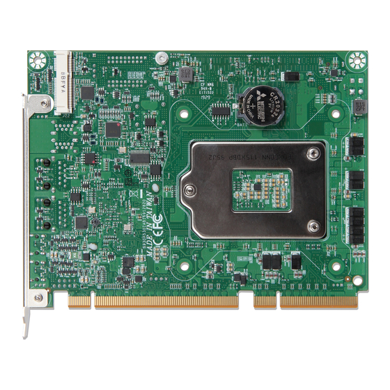
- Page 1 ROBO-6911VG2AR ROBO‐6911VG2AR Half size PICMG 1.3 Single Host Board Version 1.0 Copyright © Portwell 2017 ROBO-6911VG2AR User's Guide...
- Page 2 ROBO-6911VG2AR Revision History R1.0 Preliminary Copyright © Portwell 2017 ROBO-6911VG2AR User's Guide...
-
Page 3: Table Of Contents
5.3 Installing the Single Board Computer ....................................40 5.3.1 Chipset Component Driver ......................................40 5.3.2 Intel® HD Graphics 530 ......................................41 5.3.3 Intel LAN I210AT/I219LM Gigabit Ethernet Controller ..............................41 6 BIOS Setup Items ............................................. 42 6.1 Introduction ............................................42 Copyright © Portwell 2017 ROBO-6911VG2AR User's Guide... - Page 4 6.2.5 Save & Exit ..........................................82 7 Troubleshooting ............................................84 7.1Hardware Quick Installation ......................................84 7.2 BIOS Setting ............................................ 86 7.3 FAQ ............................................. 87 8 Portwell Software Service......................................... 93 9 Industry Specifications ..........................................94 Copyright © Portwell 2017 ROBO-6911VG2AR User's Guide...
- Page 5 Portwell provides no warranty with regard to this user’s guide or any other information contained herein and hereby expressly disclaims any implied warranties of merchantability or fitness for any particular purpose with regard to any of the foregoing. Portwell assumes no liability for any damages incurred directly or indirectly from any technical or typographical errors or omissions contained herein or for discrepancies between the product and the user’s guide.
- Page 6 Warranty”). Portwell may in its sole discretion modify its Limited Warranty at any time and from time to time. Beginning on the date of shipment to its direct customer and continuing for the published warranty period, Portwell represents that the products are new and warrants that each product failing to function properly under normal use, due to a defect in materials or workmanship or due to non conformance to the agreed upon specifications, will be repaired or exchanged, at Portwell’s option and expense.
- Page 7 Caution: Do not just hold any single side of the SBC; hold evenly on both sides! Heavy processor cooler may bend the SBC when SBC being held just on one side. The bending may cause soldering or components damaged. Copyright © Portwell 2017 ROBO-6911VG2AR User's Guide...
- Page 8 Caution: Suggest your S.I or vendor to use a metal bracket to hold/fix the desktop or server grade SBC to avoid the vibration damage during transportation. Heavy processor cooler may bend the SBC when systems are during transportation without any holder. Example: 4U chassis : Use L type mental or plastic or rubber bracket to hold SBC. Copyright © Portwell 2017 ROBO-6911VG2AR User's Guide...
- Page 9 ROBO-6911VG2AR 2U or 1U chassis: a mental bracket on the bottom of chassis to balance and support SBC from bending. Copyright © Portwell 2017 ROBO-6911VG2AR User's Guide...
-
Page 10: Introduction
Intel GbE LAN ports. It also provide one mSATA socket for storage use. For the industries who already have install based systems, ROBO-6911VG2AR not only provides a way to upgrade to use the latest Intel processors, but also supporting legacy elements such as VGA, Serial ports. -
Page 11: Specifications
Audio Interface: Mic-In / Line-Out / Line-in (on-board header) ◆ Supports dual 10/100/1000 Mbps Ethernet port (s) via PCI Express x1 interface by Intel WGI219LM and ◆ Ethernet WGI210AT controller Dual RJ45 connector on bracket ◆ High Drive GPIO ◆ Copyright © Portwell 2017 ROBO-6911VG2AR User's Guide... -
Page 12: Supported Operating Systems
◆ Board size: 167.64mm x 126.39mm, 6.6" (L) x 4.98" (W) ◆ 2.1 Supported Operating Systems The ROBO-6911VG2AR supports the following operating systems. Windows 7 support (Sky Lake only) Windows 8.1 / WEI 8.1 support Windows 10 full support Kernel.org Distribution Copyright ©... -
Page 13: Mechanical Dimensions
ROBO-6911VG2AR 2.2 Mechanical Dimensions Copyright © Portwell 2017 ROBO-6911VG2AR User's Guide... -
Page 14: Power Consumption
ROBO-6911VG2AR 2.3 Power Consumption CPU Type Intel® Xeon® CPU E3-1268L v5@2.40GHz SBC BIOS Portwell,Inc.ROBO-6911VG2AR TEST BIOS (60523T00) Memory Transcend DDR4 ECC SO-DIMM 2133 16GB*2 VGA Card Intel® HD Graphics 530 VGA Driver Intel® HD Graphics 530,Version:20.19.15.4312 LAN Card#1 Intel® Ethernet Connection(2) I219-LM LAN Driver#1 Intel®... -
Page 15: Environmental Specifications
System+ Device +3.3V 0.84A 0.73A 0.72A USB2.0 Loading Test 4.96V/ 470mA USB3.0 Loading Test 4.97V/ 980mA 2.4 Environmental Specifications Storage Temperature : -20~80°C Operation Temperature : 0~60°C Storage Humidity : 5~90% Operation Humidity: 10~90% Copyright © Portwell 2017 ROBO-6911VG2AR User's Guide... - Page 16 ROBO-6911VG2AR Block Diagram Copyright © Portwell 2017 ROBO-6911VG2AR User's Guide...
-
Page 17: Hardware Configuration
ROBO-6911VG2AR 3 Hardware Configuration 3.1 Jumpers and Connectors This chapter indicates jumpers’, headers’ and connectors’ locations. Users may find useful information related to hardware settings in this chapter. Component side Copyright © Portwell 2017 ROBO-6911VG2AR User's Guide... - Page 18 ROBO-6911VG2AR Solder side Copyright © Portwell 2017 ROBO-6911VG2AR User's Guide...
-
Page 19: Jumpers Settings
3.2 Jumpers Settings For users to customize ROBO-6911VG2AR’s features. In the following sections, Short means covering a jumper cap over jumper pins; Open or N/C (Not Connected) means removing a jumper cap from jumper pins. Users can refer to Figure 1 for the Jumper allocations. - Page 20 VGA Port Video Cable Connector BH5Px2/2mm Display Port Video Jack Molex 047272 CPU FAN Power Connector HEADER 4Px1 Audio Input/Output Connector PH5Px2(-pin10)/2.54mm mSATA Solid State Drive Socket AS0B226-S90Q Foxconn J1: Power Button Pin No. Signal Description PWRBTN Copyright © Portwell 2017 ROBO-6911VG2AR User's Guide...
- Page 21 ROBO-6911VG2AR JP1: System Reset Pin No. Signal Description RSTBTN JP2: System Buzzer Pin No. Signal Description SPEAKER (+) SPEAKER ( - ) Copyright © Portwell 2017 ROBO-6911VG2AR User's Guide...
- Page 22 ROBO-6911VG2AR JP3: Power LED Pin No. Signal Description PWR_LED (+) PWR_LED ( - ) JP4: SATA LED Pin No. Signal Description SATA_LED (+) SATA_LED ( - ) Copyright © Portwell 2017 ROBO-6911VG2AR User's Guide...
- Page 23 JP5: CMOS Clear Pin No. Function Normal Operation ★ 1-2 Short 2-3 Short Clear CMOS JP6: AT & ATX Mode Select Pin No. Function 1-2 Short ATX simulate AT Mode ATX Mode ★ 2-3 Short Copyright © Portwell 2017 ROBO-6911VG2AR User's Guide...
- Page 24 2x8 PCI Express (Support Two slot) 3-4, Open 1-2, Open 1x16 PCI Express (Support One slot) 3-4, Open Note: ROBO-6911VG2AR can support one PCIEx16 or two PCIEx8 or one PCIEx8 + two PCIEx4. Copyright © Portwell 2017 ROBO-6911VG2AR User's Guide...
- Page 25 ROBO-6911VG2AR J3: SMBus Connector Pin No. Signal Description SMBus_CLK Ground SMBus_DAT Copyright © Portwell 2017 ROBO-6911VG2AR User's Guide...
- Page 26 ROBO-6911VG2AR J4/J5/J6/J7: SATA Connector(6Gb/s) Pin No. Signal Description GND1 GND2 GND3 Copyright © Portwell 2017 ROBO-6911VG2AR User's Guide...
- Page 27 ROBO-6911VG2AR J8: ATX 4Pin 12V Power Connector Pin No. Function Ground Ground +12V +12V Copyright © Portwell 2017 ROBO-6911VG2AR User's Guide...
- Page 28 ROBO-6911VG2AR J10: External USB2 Dual Port Cable Connector PIN No. Signal Description PIN No. Signal Description 5V Dual 5V Dual USB2_DN8 USB2_DN9 USB2_DP8 USB2_DP9 Ground Ground Key( no pin ) Copyright © Portwell 2017 ROBO-6911VG2AR User's Guide...
- Page 29 ROBO-6911VG2AR J11: LPC PORT 80 Debug Port Connector PIN No. Signal Description PIN No. Signal Description LAD0 VCC3 LAD1 PLT_REST LAD2 LFRAME# LAD3 Key( no pin ) Ground Copyright © Portwell 2017 ROBO-6911VG2AR User's Guide...
- Page 30 J12: Internal USB3 Dual Port Cable Connector PIN No. Signal Description PIN No. Signal Description 5V Dual USB3_RX1_DN USB3_RX1_DP Ground USB3_TX1_DN USB3_TX1_DP Ground USB2_DN2 USB2_DP2 Ground USB2_DP3 USB2_DN3 Ground USB3_TX2_DP USB3_TX2_DN Ground USB3_RX2_DP USB3_RX2_DN 5V Dual Copyright © Portwell 2017 ROBO-6911VG2AR User's Guide...
- Page 31 J13: DVI Port Cable Connector PIN No. Signal Description PIN No. Signal Description Ground Ground DVI_D2_DP DVI_D3_DP DVI_D2_DN DVI_D3_DN Ground Ground DVI_D1_DP DVI_POWER (+5V) DVI_D1_DN DVI_POWER (+5V) Ground DVI_HPD_N DVI_D0_DP DVI_DDC_CLK DVI_D0_DN DVI_DDC_DATA Ground Ground Copyright © Portwell 2017 ROBO-6911VG2AR User's Guide...
- Page 32 ROBO-6911VG2AR J14: COM1 Box Header PIN No. Signal Description PIN No. Signal Description DCD# RXD# TXD# DTR# Ground DSR# RTS# CTS# Copyright © Portwell 2017 ROBO-6911VG2AR User's Guide...
- Page 33 ROBO-6911VG2AR J19: VGA Box Header PIN No. Signal Description PIN No. Signal Description DDC_CLK Green Ground Blue DDC_DATA V_SYNC Ground H_SYNC Copyright © Portwell 2017 ROBO-6911VG2AR User's Guide...
- Page 34 ROBO-6911VG2AR J21: CPU Fan Connector Pin No. Signal Description Ground +12V Detect Fan RPM speed Fan Speed control Copyright © Portwell 2017 ROBO-6911VG2AR User's Guide...
- Page 35 J22: Audio MIC/Line-in/Line-out Connector PIN No. Signal Description PIN No. Signal Description Analog Ground Line-in Left Channel Analog Ground Line-in Right Channel Analog Ground Line-out Left Channel Analog Ground Line-out Right Channel Key( no pin ) Copyright © Portwell 2017 ROBO-6911VG2AR User's Guide...
-
Page 36: Signal Descriptions
#Define WDTMIN 0x07 //WDT Timer Counter Register (Minute) #Define WDTSEC 0x08 //WDT Timer Counter Register (Second) VOID Write_EC_SRAM(UINT8 Offset,UINT8 Value){ IoWrite8(0xE300+Offset,Value); Byte Read_EC_SRAM(UINT8 Offset){ IoRead8(0xE300+offset,Value); return Value; void WDT() // Enable WDT 30sec Copyright © Portwell 2017 ROBO-6911VG2AR User's Guide... - Page 37 Write_EC_SRAM(WDTCFG,0x01); //Bit0: WDT Enable, BIT1: 0:Second Mode // Enable WDT 5min Write_EC_SRAM(WDTSEC,5); Write_EC_SRAM(WDTCFG,0x03); //Bit0: WDT Enable, BIT1: 1:Minute Mode // Enable WDT 10min, 20sec Write_EC_SRAM(WDTSEC,20); Write_EC_SRAM(WDTSEC,10); Write_EC_SRAM(WDTCFG,0x03); //Bit0: WDT Enable, BIT1: 1:Minute Mode Copyright © Portwell 2017 ROBO-6911VG2AR User's Guide...
-
Page 38: Gpio Signal
ROBO-6911VG2AR 4.2 GPIO Signal ROBO-6911VG2AR series don’t support GPIO function. Copyright © Portwell 2017 ROBO-6911VG2AR User's Guide... -
Page 39: System Resources
Intel® C236 Chipset (Intel® GL82C236 PCH) 5.2 Main Memory ROBO-6911VG2AR provides 2 x 260-pin SODIMM sockets which supports DDR4 ECC/non-ECC memory. The maximum memory can be up to 32GB. Memory clock and related settings can be detected by BIOS via SPD interface. -
Page 40: Installing The Single Board Computer
To overcome this compatibility issue, for Windows Operating Systems such as Windows 8, please install its INF before any of other Drivers are installed. You can find very easily this chipset component driver in ROBO-6911VG2AR CD-title Copyright ©... -
Page 41: Intel® Hd Graphics 530
5.3.2 Intel® HD Graphics 530 ROBO-6911VG2AR has integrated Intel® HD Graphics 530 which supports DirectX 12、OpenCL 2.0、OpenGL 4.4. It is the most advanced design to gain an outstanding graphic performance. ROBO-6911VG2AR supports VGA, DVI-D and DP display output. This combination makes ROBO-6911VG2AR an excellent performance hardware. -
Page 42: Bios Setup Items
The following section describes the BIOS setup program. The BIOS setup program can be used to view and change the BIOS settings for the module. Only experienced users should change the default BIOS settings. Copyright © Portwell 2017 ROBO-6911VG2AR User's Guide... -
Page 43: Bios Setup
The BIOS setup program provides a General Help screen. The menu can be easily called up from any menu by pressing <F1>. The Help screen lists all the possible keys to use and the selections for the highlighted item. Press <Esc> to exit the Help Screen. Copyright © Portwell 2017 ROBO-6911VG2AR User's Guide... -
Page 44: Main
ROBO-6911VG2AR 6.2.1 Main Use this menu for basic system configurations, such as time, date etc. Copyright © Portwell 2017 ROBO-6911VG2AR User's Guide... - Page 45 The date format is <Day>, <Month> <Date> <Year>. Use [+] or [-] to configure system Date. System Date The time format is <Hour> <Minute> <Second>. Use [+] or [-] to configure system Time. System Time Copyright © Portwell 2017 ROBO-6911VG2AR User's Guide...
-
Page 46: Configuration
ROBO-6911VG2AR 6.2.2 Configuration Use this menu to set up the items of special enhanced features Copyright © Portwell 2017 ROBO-6911VG2AR User's Guide... - Page 47 ROBO-6911VG2AR CPU Configuration CPU Configuration Parameters Copyright © Portwell 2017 ROBO-6911VG2AR User's Guide...
- Page 48 Intel® Speed Step™ Allows more than two frequency ranges to be supported. ★ Enabled, Disabled Turbo Mode Turbo Mode. ★ Enabled, Disabled CPU C states Enable or disable CPU C states ★ Disabled, Enabled Copyright © Portwell 2017 ROBO-6911VG2AR User's Guide...
- Page 49 ROBO-6911VG2AR Chipset Configuration Configuration Chipset feature Copyright © Portwell 2017 ROBO-6911VG2AR User's Guide...
- Page 50 Disabled = HAD will be unconditionally disabled ★ Enabled, Disabled Enabled = HAD will be unconditionally Enabled Port 80h Redirection Control where the port 80h cycles are sent. ★ LPC Bus, PCIE Bus Copyright © Portwell 2017 ROBO-6911VG2AR User's Guide...
- Page 51 ROBO-6911VG2AR AMT Configuration Configure Active Management Technology Parameters Copyright © Portwell 2017 ROBO-6911VG2AR User's Guide...
- Page 52 ★ Disabled, Enabled (Enabled) This option just controls the BIOS extension execution. If enabled, this requires additional firmware in the SPI device Un-Configure ME OEMFlag Bit 15: Un-Configure ME without password. ★ Disabled, Enabled Copyright © Portwell 2017 ROBO-6911VG2AR User's Guide...
- Page 53 ROBO-6911VG2AR LAN Configuration Configuration on Board LAN device configuration. Copyright © Portwell 2017 ROBO-6911VG2AR User's Guide...
- Page 54 Enable or disable integrated LAN to wake the system. (The Wake On LAN cannot be disabled if Wake on LAN I210-AT ★ Disabled, Enabled ME is on at Sx state.) Launch Legacy PXE Rom Launch Legacy PXE Rom. [Disable] Not launch Rom, [Enable] Force launch Rom ★ Disable, Enable Copyright © Portwell 2017 ROBO-6911VG2AR User's Guide...
- Page 55 ROBO-6911VG2AR Graphics Configuration Configuration Graphics Settings Copyright © Portwell 2017 ROBO-6911VG2AR User's Guide...
- Page 56 Secondary boot display selection will appear base on your selection. VGA Display Port,DVI,VGA modes will be supported only on primary display. ★ Disabled,Display Secondary IGFX Boot Display Select Secondary Display Device Port,DVI,VGA Copyright © Portwell 2017 ROBO-6911VG2AR User's Guide...
- Page 57 ROBO-6911VG2AR PCI/PCIE Configuration PCI, PCI-X and PCI Express Settings. Copyright © Portwell 2017 ROBO-6911VG2AR User's Guide...
- Page 58 ROBO-6911VG2AR PCI Express Root Port 5 PCI Express Root Port 5 Copyright © Portwell 2017 ROBO-6911VG2AR User's Guide...
- Page 59 Force L0s – Force all links to L0s State ★ Disabled, L0s, L1, L0sL1, ASPM Support AUTO-BIOS auto configure Auto DISABLE – Disables ASPM PCIe Speed Select PCI Express port speed ★ Auto, Gen1, Gen2, Gen3 Copyright © Portwell 2017 ROBO-6911VG2AR User's Guide...
- Page 60 ROBO-6911VG2AR SATA Configuration SATA Device Options Settings Copyright © Portwell 2017 ROBO-6911VG2AR User's Guide...
- Page 61 ★ Disabled, Enabled External SATA External SATA Support. ★ Disabled, Enabled ★ Hard Disk Drive, Solid State SATA Device Type Indentify the SATA port is connected to Solid State Drive or Hard Disk Drive. Drive Copyright © Portwell 2017 ROBO-6911VG2AR User's Guide...
- Page 62 ROBO-6911VG2AR USB Configuration USB Configuration Parameters. Copyright © Portwell 2017 ROBO-6911VG2AR User's Guide...
- Page 63 Mass Storage device emulation type. ‘AUTO’ enumerates devices according to their media ★ Auto, Floppy, Forced FDD, Mass Storage Devices format. Optical drives are emulated as ‘CDROM’, drives with no media will be emulated Hard Disk, CD-ROM according to a drive type. Copyright © Portwell 2017 ROBO-6911VG2AR User's Guide...
- Page 64 ROBO-6911VG2AR PCH USB Configuration PCH USB Configuration Copyright © Portwell 2017 ROBO-6911VG2AR User's Guide...
- Page 65 Selectively Enable/Disable the corresponding USB port from reporting a Device ★ Disabled, Select Per-Pin (Select Per-Pin) Connection to the controller. USB HS Physical Connector #0 - #9 Enable/Disable USB Port. ★ Enabled, Disabled Copyright © Portwell 2017 ROBO-6911VG2AR User's Guide...
- Page 66 ROBO-6911VG2AR Power Control Configuration System Power Control Configuration Parameters Copyright © Portwell 2017 ROBO-6911VG2AR User's Guide...
- Page 67 Wake up day 1-31 like the system to wake up Wake up Time(HH: mm: ss) Use [Enter], [TAB] to select field, HH: 0-23, mm: 0-59, ss: 0-59 HH: 0-23, mm: 0-59, ss: 0-59 Copyright © Portwell 2017 ROBO-6911VG2AR User's Guide...
- Page 68 Description Options Watch Dog Timer Enable/Disable Watch Dog Timer ★ Disabled, Enabled (Enabled) Timer Unit Select Timer count unit of WDT ★ Second, Minute Timer value Set WDT Timer value seconds/minutes ★ 20 Copyright © Portwell 2017 ROBO-6911VG2AR User's Guide...
- Page 69 ROBO-6911VG2AR Serial Port 1 Configuration Set Parameters of Serial Port 1 (COM1) Copyright © Portwell 2017 ROBO-6911VG2AR User's Guide...
- Page 70 RS-232/422/485 Control Option Serial Port 1 RS-232/422/485 Control Option RS-485 HALF DUPLEX, RS-485/422 FULL DUPLEX ★ IO=3F8h; IRQ=4, Auto, IO=3F8h; IRQ=3,4,5,6,7,9,10,11,12 Change Settings Select an optimal settings for Super IO Device IO=2F8h; IRQ=3,4,5,6,7,9,10,11,12 IO=3E8h; IRQ=3,4,5,6,7,9,10,11,12 IO=2E8h; IRQ=3,4,5,6,7,9,10,11,12 Copyright © Portwell 2017 ROBO-6911VG2AR User's Guide...
- Page 71 ROBO-6911VG2AR H/W Monitor Configuration Monitor hardware status Copyright © Portwell 2017 ROBO-6911VG2AR User's Guide...
- Page 72 Smart System Fan Function Enable or Disable Smart System Fan ★ Disabled, Enabled (Enabled) System Start Target Temp System Start Fan Target Temperature. System Full Target Temp System Full Fan Fan Target Temperature. Copyright © Portwell 2017 ROBO-6911VG2AR User's Guide...
- Page 73 ROBO-6911VG2AR Serial Port Console Redirection Serial Port Console Redirection Copyright © Portwell 2017 ROBO-6911VG2AR User's Guide...
- Page 74 ROBO-6911VG2AR Feature Description Options Console Redirection Console Redirection Enable or Disable. ★ Disabled, Enabled (Enabled) Copyright © Portwell 2017 ROBO-6911VG2AR User's Guide...
- Page 75 ROBO-6911VG2AR COM 0 Serial Port Console Redirection Settings COM0 Serial Port console Redirection settings Copyright © Portwell 2017 ROBO-6911VG2AR User's Guide...
- Page 76 ‘stop’ signal can be sent to stop the data flow. Once Flow Control ★ None, Hardware RTS/CTS the buffers are empty, a ‘start’ signal can be sent to re-start the flow. Hardware flow control uses two wires to send start/stop signals. Copyright © Portwell 2017 ROBO-6911VG2AR User's Guide...
- Page 77 The settings specify if BootLoader is selected then Legacy console redirection is Redirection After BIOS POST disabled before booting to legacy OS. Default value is Always Enable which ★ Always Enable, BootLoader means Legacy console Redirection is enabled for Legacy OS. Copyright © Portwell 2017 ROBO-6911VG2AR User's Guide...
-
Page 78: Security
ROBO-6911VG2AR 6.2.3 Security This section lets you set security passwords to control access to the system at boot time and/or when entering the BIOS setup program. Copyright © Portwell 2017 ROBO-6911VG2AR User's Guide... - Page 79 Password Check Mode ★ Setup, Power on [Power on] check password on every time system power on. Administrator Password Set Administrator Password ★ No default setting 1st-5th HDD Security HDD Security Configuration for selected drive. Copyright © Portwell 2017 ROBO-6911VG2AR User's Guide...
-
Page 80: Boot
ROBO-6911VG2AR 6.2.4 Boot Use this menu to specify the priority of boot devices. Copyright © Portwell 2017 ROBO-6911VG2AR User's Guide... - Page 81 Summary Screen Support Enabled/Disabled ★ Disabled, Enabled Boot option filter This option controls Legacy/UEFI ROMs priority ★ Legacy only, UEFI only Hard Drive BBS Priorities Set the order of the legacy devices in this group Copyright © Portwell 2017 ROBO-6911VG2AR User's Guide...
-
Page 82: Save & Exit
ROBO-6911VG2AR 6.2.5 Save & Exit Copyright © Portwell 2017 ROBO-6911VG2AR User's Guide... - Page 83 UEFI: Built-in EFI Shell Reset the system after saving the changes. (Boot option filter: UEFI only) Attempts to Launch EFI Shell application (Shell.efi) from one of the available Launch EFI Shell from filesystem device filesystem devices. Copyright © Portwell 2017 ROBO-6911VG2AR User's Guide...
-
Page 84: Troubleshooting
7 Troubleshooting This chapter provides a few useful tips to quickly get ROBO-6911VG2AR running with success. As basic hardware installation has been addressed in Chapter 2, this chapter will focus on system integration issues, in terms of BIOS setting, and OS diagnostics. - Page 85 ROBO-6911VG2AR ROBO-6911VG2AR can support four(J4/J5/J6/J7) SATA interface (SATAIII, 6.0Gb/s) and one mSATA(J24) interface on board; The SATA interface shall support 1.5Gb/ 3.0Gb & 6.0Gb operation per the SATA specification. Copyright © Portwell 2017 ROBO-6911VG2AR User's Guide...
-
Page 86: Bios Setting
BIOS setup. This will force your BIOS setting back to the initial factory configurations. It is recommended to do this so you can be sure the system is running with the BIOS setting that Portwell has highly endorsed. As a matter of fact, users can load the default BIOS setting at any time when system appears to be unstable in boot up sequence. -
Page 87: Faq
Question: I forgot my password of system BIOS, what am I supposed to do? Answer: You can switch off your power supply then find the JP5 on the ROBO-6911VG2AR SBC to set it from 1-2 short to 2-3 short and wait 5 seconds to clean your password then set it back to 1-2 short to switch on your power supply. - Page 88 ROBO-6911VG2AR Question: How to update the BIOS file of ROBO-6911VG2AR? Answer: 1. Please visit web site of Portwell download center as below hyperlink http://www.portwell.com.tw/support/download_center.php Registering an account in advance is a must. (The E-Mail box should be an existing Company email address that you check regularly.) http://www.portwell.com.tw/member/newmember.php...
- Page 89 If you have other additional technical information or request which is not covered in this manual, please fill in the technical request form as below hyperlink. http://www.portwell.com.tw/support/problem_report.php We will do our best to provide a suggestion or solution for you. Thanks Copyright © Portwell 2017 ROBO-6911VG2AR User's Guide...
- Page 90 B. Click the Windows Start button, and click Windows7 USB/DVD Download Tool to execute. C. Choosing the ISO file, type the name and path of your Windows ISO file, or click Browse and select the file from the open dialog box. Click Next. Copyright © Portwell 2017 ROBO-6911VG2AR User's Guide...
- Page 91 Please navigate to the USB3_Fix folder in the cmd shell, and type in the following commands in this order to update the boot.wim file: (1) dism /mount-wim /wimfile:boot.wim /index:2 /mountdir:mount (2) dism /image:mount /add-driver:"usb3" /recurse Copyright © Portwell 2017 ROBO-6911VG2AR User's Guide...
- Page 92 7. Please copy both two file back to the \source of the root of your USB bootable device. Then you can install the Win7 O/S which has been included the USB3.0 driver by USB bootable device. Copyright © Portwell 2017 ROBO-6911VG2AR User's Guide...
-
Page 93: Portwell Software Service
Portwell. Portwell BIOS web Tool (PBT) The Portwell BIOS web Tool (PBT) is a brand new on-line utility which innovated by Portwell. PBT now is available for Portwell's premiere customers who are able to add customized BIOS logo change BIOS default settings on American Megatrends (AMI) BIOS. -
Page 94: Industry Specifications
ROBO-6911VG2AR 9 Industry Specifications The list below provides links to industry specifications that apply to Portwell modules. Low Pin Count Interface Specification, Revision 1.0 (LPC) http://www.intel.com/design/chipsets/industry/lpc.htm Universal Serial Bus (USB) Specification, Revision 2.0 http://www.usb.org/home PCI Specification, Revision 2.3 https://www.pcisig.com/specifications Serial ATA Specification, Revision 3.0 http://www.serialata.org/...
Need help?
Do you have a question about the ROBO-6911VG2AR and is the answer not in the manual?
Questions and answers