Table of Contents
Advertisement
Advertisement
Table of Contents

Related Manuals for Esaote O-scan Series


Summary of Contents for Esaote O-scan Series
- Page 3 O-scan User Manual 350004900 Rev. 07 Esaote S.p.A. Genoa...
-
Page 4: Manufacturer's Address
Edition April 2020 Guarantee The information in this document are the exclusive property of Esaote S.p.A. and are reserved. Reproduction or distribution in any form is strictly prohibited. All rights reserved. Translations of this document are strictly prohibited without prior authorization from Esaote S.p.A. - Page 5 10 rue de Temara CS 40343 78105 Saint Germain en Laye Cedex France Tel. +33 1 82048950 Fax +33 1 34512420 info@esaote.fr ESAOTE BIOMEDICA DEUTSCHLAND GmbH Max-Planck-Str 27a 50858 Köln Germany Tel. +49 223 46885600 Fax +49 223 49679628 info@esaote.de...
- Page 6 1004 Buenos Aires - Argentina Tel. +54 11 4326 1832 Fax +54 11 4328 1245 info@esaote.com.ar ESAOTE HEALTHCARE DO BRASIL Rua Dr. Tomàs Carvalhal 711 CEP 04006-001 San Paulo - Brasil Tel. +55 11 2789 0400 Fax +55 11 2789 0432 edson.lopes@esaote.com...
- Page 7 135 Bonham Strand, Sheung Wan, Hong Kong - China Tel. +852 25458386 Fax +852 25433068 esaote@esaotechina.com SHENZEN ESAOTE MEDICAL TECHNOLOGY CO. LTD. 1st Floor, icoEsaote B2 Shenzhen Digital Technology Park Xinnan 7 Lu, Gaoxin Kejiyuan South Area, Nanshan Dist., 518057 Shenzhen - People’s Republic of China...
- Page 8 Therefore, in the event of malfunctions, defective performance of the equipment, or inadequate instructions, which may constitute a hazard to the patient or operator, the user must notify ESAOTE S.p.A., associate company or authorized distributor in writing, providing the information as specified in the form below.
- Page 9 • • • 350004900 Rev. 07 7 / 10 • • •...
- Page 10 • • • 8 / 10 • • •...
- Page 11 93/42/EEC and subsequent amendments, original owners, in the event of equipment transfer to third parties, are requested to notify ESAOTE S.p.A., associate company or authorized distributor of the said transfer by means of the following form, duly compiled, or written notification with the same data as specified in the form.
- Page 12 • • • 10 / 10 • • •...
- Page 13 INDEX • • • • • • Chapter 1 - Essential prescribing information Description of the system ....... 1 New Information .
- Page 14 Operating Mode ........15 Personnel and patient exposure to the acoustic noise .
- Page 15 Chapter 4 - Installation Structural Requirements of the Installation Area ....1 Electromagnetic requirements in the installation environment ..2 Electromagnetic compatibility (EMC) ....2 Recommended distences between RF communication systems and O-scan .
- Page 16 Imaging system ....... . . 13 Magnetic System ....... . 14 Special purpose gradient system .
- Page 17 Chapter 8 - Coils Dual Phased Array Coils ....... 1 Description of DPA Knee Coil 1 .
- Page 18 Cushions and insulating straps ......2 Patient Positioning Procedure ......2 Chapter 13 - Foot - Ankle Region Examinations Usable coils .
- Page 19 Control panel ........1 Real time positioning .
- Page 20 • • • 8 / 8 • • •...
-
Page 21: Essential Prescribing Information
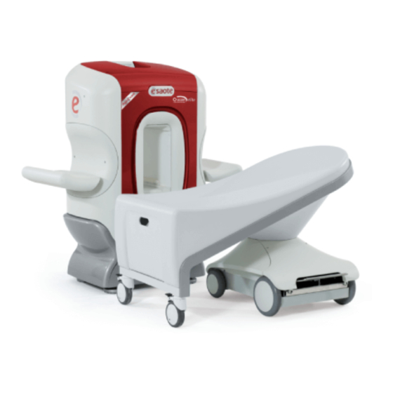
HAPTER Essential prescribing information • • • • • • W a r n i n g Federal law restricts this device to sale, distribution and use by or on the order of a physician. The device is limited by Federal law to investigational use for indications not in the Intended Use/Indications statement. - Page 22 fig. 1.1 - The O-scan system Important Information The user manual has been divided into three parts (System and Patient Positioning User Manual, Image Quality and Sequences Manual, User Interface Manual). These combined provide all instructions necessary for safe and efficient use of the system. All information included in the user manual refer to the O-scan system and its configurations O-scan eXP and O-scan Premium.
-
Page 23: Intended Use
Intended Use O-scan is a Magnetic Resonance (MR) system that produces transversal, sagittal, coronal and oblique section images of limbs and joints. It is designed for imaging portions of the arm, including hand, wrist, forearm, and elbow, but excluding the upper part of the arm and portions of the leg, including foot, ankle, calf, and knee, but excluding the thigh. - Page 24 To avoid degradation of image quality or lost time for re-establishing magnet temperature, do not disconnect the main power supply to the system except for emergency stops, maintenance or other necessary procedures. Allow only Esaote-authorized service personnel to perform maintenance, modification and repair procedures on O-scan systems. • •...
- Page 25 LCD TFT Monitor User Manual supplied with the product • CD/DVD drive User Manual supplied with the product The original language of all the O-scan User Manuals is Italian. Esaote S.p.A. has had these manuals translated into English, German, Spanish and Portuguese.
-
Page 26: Special Terms
Cautions throughout the entire manual. The term “Service”, when used in the O-scan manual, always refers to the service personnel authorized by Esaote S.p.A.. Special Terms The purpose of this section is to provide a list of “special terms” frequently... - Page 27 EER - Acronym for Early Enhancement Rate indicating the capture speed of the contrast bolus. EFFECTIVENESS - Accuracy and completeness with which the operator reaches set objectives. EFFICIENCY - Resources used in relation to the accuracy and completeness with which the operator reaches set objectives. FERROMAGNETIC - A large positive magnetic susceptibility in a substance, such as iron.
- Page 28 INHOMOGENEITY - Degree of a lack of homogeneity. For example, the fractional deviation of the local magnetic field from the average value of the field. LONGITUDINAL MAGNETIZATION - Component of the macroscopic magnetization vector along the static magnetic field. LOWER LIMB - Includes foot, ankle, calf, and knee, but which excludes the thigh.
- Page 29 NOT SAFE FOR USE IN M.R. ENVIRONMENT - This indicates that a device generates known risks in all M.R. environments. The icon has a black text on a white background with a red border, and the text has a red strike-through line; alternatively it may be shown in white and black.
- Page 30 RESPONSIBLE ORGANIZATION - Organizational aspects of safety are the task of the RESPONSIBLE ORGANIZATION. This task includes adequate training of staff, rules of access to the MR SYSTEM, qualification of staff for decisions that are related to safety, definition of medical responsibility and specific requirements for personnel following from that responsibility when the PATIENT is in or near the MR SYSTEM.
- Page 31 TESLA - The unit of measure of the magnetic field. TRANSVERSE MAGNETIZATION Component macroscopic magnetization vector at right angles to the static magnetic field. UPPER LIMB - Includes hand, wrist, forearm and elbow, but which excludes the arm. USER – Any person or entity that owns or controls a O-scan system, or is responsible for the maintenance, safe, effective and appropriate use of that system.
- Page 32 • • • 8 / 8 Chapter 2 • • •...
-
Page 33: Instructions For Safe Use
MR equipment and the safety of patients, MR worker and others. C a u t i o n This product may only be used with original Esaote S.p.A. accessories or accessories distributed by Esaote authorized third-parties. C a u t i o n... -
Page 34: Operator Profile
Safe and efficient use of O-scan requires patient examinations to be supervised and performed by qualified personnel, who are licensed and certified by appropriate local, state, or federal authorities. Esaote provides on-site training, by Esaote representatives, or by authorized third-party personnel, following system installation or major system modifications. -
Page 35: Use Environment
• The audio visual condition to allow routine monitoring and medical supervision of the patient. Use environment The use environment is intended as the actual conditions and settings in which users interact with the medical device. O-scan is designed to be used: in public or private hospital environments medical studios... -
Page 36: Peripheral Equipment
W a r n i n g Do not allow any persons, who have the conditions and characteristics for which exposure to the O-scan magnetic and RF fields is contraindicated, to enter the 0.5 mT restricted area. W a r n i n g Users are advised to affix the warning and prohibition labels provided with the equipment on all of the doors of the O-scan examination room. - Page 37 Before using the peripheral equipment, the user must ensure electrical insulation of conductive materials, except for those that must guarantee electrical contact with the patient (e.g. ECG electrodes). Also the conductive material of the peripheral equipment should be thermally insulated if it comes into contact with the patient. Never use ECG electrodes after the expiry date specified by the manufacturer.
- Page 38 W a r n i n g All metal objects must be kept clear of the 0.5 mT controlled access area limit. Ferromagnetic objects can become projectiles that may cause serious injury to patients, operators and others. Artifacts Large, moving ferromagnetic objects, for example a stretcher, may disturb the uniformity of the magnetic field, causing artifacts to appear in the displayed image.
- Page 39 In this case, the user should contact Esaote-authorized service personnel for assistance. W a r n i n g Artifacts on images can be caused by loss in efficiency of the shielding elements and possible magnetic compensation.
- Page 40 • Gradient Echo 10, to assess susceptibility of the system to electromagnetic disturbance caused by peripheral equipment. The parameters are: TE = 10 ms, TR = 500 ms, FOV = 200*200, acquisition matrix = 256*256, number of slices = 11, slice thickness = 5 mm, gap = 0 mm, number of excitations = 6.
- Page 41 Pre-screening of patients The user must make a careful evaluation of the risks associated with the personal and clinical history of patients, their psychological and physical conditions and profession before performing an examination using the O-scan system. The evaluation should identify any contraindications that would preclude the examination and any special precautions that should be taken before or during the examination.
- Page 42 SPECIAL PRECAUTIONS: PATIENTS WITH METAL OBJECTS IN THE BODY The M.R. examination requires special precautions: patients with surgical clips (haemostatic clips) other ferromagnetic implants labeled as MR Conditional for patients with implanted prosthetic heart valves labeled as MR Conditional for patients with non-ferromagnetic metal implants labeled as MR Conditional for patients who due to their professional activity or personal history (e.g.
- Page 43 C a u t i o n Ferromagnetic and non-ferromagnetic metal implants may cause artifacts. The physician must be made aware of the implants in order to correctly evaluate the possible artifacts and avoid an incorrect interpretation of the images. W a r n i n g Never examine patients suspected of having microscopic metal fragments in the eyes and prohibit entry of the latter in the controlled...
- Page 44 W a r n i n g Pregnant women and newborn babies must be examined by the supervising physician before entry in the controlled access area, to evaluate the benefits of magnetic resonance with respect to alternative procedures. The safety of magnetic resonance imaging for newborn babies, infants, embryos, and fetuses has not been demonstrated.
- Page 45 Pre-screening of MR Personnel The user must make a careful evaluation of the risks associated with the personal and clinical history of MR personnel, their psychological and physical conditions and professional tasks assigned before entering the controlled access area. The evaluation should identify any contraindications that would preclude personnel access controlled...
- Page 46 W a r n i n g The O-scan magnet is a permanent magnet and its static magnetic field cannot be de-activated in an emergency. Never use resuscitation devices such as defibrillators, oxygen tanks, etc., within the controlled access area. Remove the patient from the influence of the magnet, following the procedure described in the chapter “Positioning Protocols”...
-
Page 47: Operating Mode
Operating Mode The O-scan operating mode for all supported sequences is the Normal Operating Mode as defined by the EN 60601-2-33 and subsequent amendments. This means that the values of static magnetic field, gradient output and SAR measured on the O-scan system do not exceed the limits specified by the standard for Normal Operating Mode and consequently no specific information or measurements are displayed on the system user interface. -
Page 48: Excessive Noise
Personnel and patient exposure to the acoustic noise Excessive Noise The weighted sound pressure level (LAeq, 1 h) generated by the O-scan system, measured according to paragraph 26 of standard EN 60601-2-33, is below 99 dB(A). The non-weighted sound pressure level (Lp) generated by the O-scan system, measured according... - Page 49 Personnel and patient exposure to the static magnetic field The issues related to safety to be considered as regards MR worker and patient exposure to the static magnetic field, are the biological effects, projectile effects, safety and compatibility of implanted medical devices and the compatibility of the peripheral equipment.
- Page 50 MR personnel Exposure to the static magnetic field can be minimised by staying away from the magnet and avoiding rapid movements of the head while in the static magnetic field. It is generally accepted that no published evidence supporting the occurrence of cumulative and/or long-term effects after exposure to EMF emitted by the MR systems exists.
- Page 51 fig. 3.1 - Top view • • • 350004900 Rev. 07 19 / 48 • • •...
- Page 52 fig. 3.2 - Side view • • • 20 / 48 Chapter 3 • • •...
- Page 53 fig. 3.3 - Front view A t t e n t i o n The measured magnetic flux density may vary from the contour plots due to factors such as concentrating effects of nearby ferrous objects and ambient fields, including the earth's magnetic field. •...
- Page 54 Main magnetic field and main magnetic field gradient In the position in which the spatial gradient of the main magnetic field is maximum, the force exerted on a ferromagnetic object saturated by the spatial gradient of the main magnetic field is maximum. In the position in which the result of amplitude of the main magnetic field and spatial gradient of the main magnetic field is maximum, the force exerted on a diamagnetic or paramagnetic object, or a ferromagnetic...
- Page 55 fig. 3.4 - Regions of maximum magnetic field and magnetic field gradient The values measured in the defined regions are as follows: Maximum main magnetic field: B0 = 1.1027 mT Maximum spatial gradient of main magnetic field: 9,2398 T/m Maximum result: (B0) x (spatial gradient B0) = 10.1887 mT Personnel and patient exposure to the time-varying magnetic field A time-varying magnetic field induces an electric field E according to Faraday's Law.
- Page 56 Patient The field intensity increases on approach to the side walls of the gantry, where the gradient coils are located, and therefore - during examinations of larger size patients - it is necessary to minimize the dB/dt influence on parts of the body not being examined, but that are close to the gantry walls during the examination.
- Page 57 fig. 3.5 - Spatial distribution of the magnetic field gradient along the Z axis fig. 3.6 - Spatial distribution of the magnetic field gradient along the Z axis: detail showing correspondence with system covers Exposure of the operator falls below the action values of: 0.1 mT –...
- Page 58 MR personnel and patient exposure to the RF magnetic field Heating is a major consequence of exposure to the RF frequencies used in M.R. Many biological effects of acute exposure to radio frequency are consistent with responses to induced heating that results from rises in tissue or body temperature of about 1°...
- Page 59 fig. 3.7 - B normalized with respect to value at isocenter Conformance to the directive 2013/35/EC requires that SAR values do not exceed a threshold, defined as the exposure limit value, of 10 W/kg for the head and trunk and 20 W/kg for the limbs. The exposure limit value for parts of the body with the O-scan system is less than or equal to 8.1 W/kg (as reported in the paragraph “Operating mode”...
- Page 60 It is generally accepted that no published evidence supporting the occurrence of cumulative and/or long-term effects after exposure to EMF emitted by the MR systems exists. MR personnel and patient exposure to contact currents Contact current is the current produced when a person comes into contact with conductor with...
- Page 61 parts of the body in contact with the surface of the transmission coil:for this purpose, use the insulating strap to avoid contact from body part and the gantry surface presence of electric cables inside the gantry presence of garments containing threads or metal components inside the gantry presence of damp clothing presence of metal objects such as watches, coins, keys, etc.
- Page 62 Special Precautions for Patient Positioning When used properly for examinations within the scope of its intended use, O-scan can be used safely and effectively for most patients. However, the compact design of the system implies a number of dimensional restrictions that may limit or exclude the possibility of patient examinations.
- Page 63 W a r n i n g To avoid possible misinterpretation of images, it is the User's responsibility to verify that the anatomy to be examined is correctly positioned in the center of homogeneity region of the magnet, by using the Scout sequence, and observing the initial scans. W a r n i n g Because of displayed image constraints, O-scan is not recommended for use in evaluation of diffuse pathologies that may extend beyond...
- Page 64 Precautions against Mechanical Hazards In compliance with standard EN 60601-1 and subsequent amendments, all parts of the O-scan system are mechanically stable. It is advisable, however to take some precautions. Patient seat (see chapter 6 in this document) W a r n i n g The maximum load capacity for the patient seat is 150 kg.
- Page 65 The device for cinematic examinations of the knee is not designed to accommodate the seated patient and/or operator. Precautions against Electric Shock All installation, maintenance or repair procedures must be carried out by Esaote authorized service personnel. • • •...
- Page 66 If the equipment operates abnormally in any way, switch off the console and the main power supply so that the thermostat is also disconnected. Contact Esaote authorized service personnel and provide as much information about the irregularity as possible. Service personnel will call for inspection and any necessary repairs.
- Page 67 Fire and Explosion Precautions The precautions to be adopted in the event of fire and/or explosion must be discussed with the local fire-fighting department. The user is responsible for taking adequate fire prevention measures in the area of installation and to establish an emergency procedure in case of fire and/or explosion.
- Page 68 Precautions when using the contrast agent in MR examinations. During an examination using the dynamic acquisition method, the use of paramagnetic contrast agents is standard, which reduces the T1 value of certain tissues, thereby increasing their contrast with adjacent ones. As paramagnetic contrast means are pharmaceuticals to all effects and purposes, a number of precautions should be taken before use.
- Page 69 Disinfecting and cleaning the system Before describing the procedure for disinfecting and cleaning the system, the user must be familiar with the following definitions: DETERSION- Mechanical procedure for removing a high percentage of microorganisms and organic/inorganic material. DETERGENT - Substance that reduces surface tension between dirt and surface to aid removal.
- Page 70 All external surfaces of the magnetic and electronic unit and operating console must be cleaned with neutral pH factor and solvent free detergent and dried thoroughly. Surfaces that are likely to become soiled from direct contact with the patient or the operator are: the gantry walls, the coils, insulating strap.
-
Page 71: Periodic Maintenance
Periodic maintenance O-scan requires certain periodic maintenance procedures that are to be performed by Esaote authorized service personnel. The maintenance operations and schedule are provided in the table below: Maintenance Frequency Backup of calibration, configuration and user protocols of the... -
Page 72: Quality Assurance
(S/N) of a standard image, to verify the stability of system image quality. This test is accessible to the user and should be performed after each system start-up. It is performed periodically by Esaote technical personnel during the maintenance procedures. - Page 73 Press Ok to close the dialog window and the system is ready to use. “Auto Shimming Correction performed. Request Technical Assistance”. This means that the system has not automatically performed the shimming correction process on the static magnetic field and Esaote • • • 350004900 Rev. 07 41 / 48 • •...
- Page 74 The assembly, maintenance, extensions, adjustments, modifications, and repairs are carried out exclusively by authorized Esaote personnel and with original Esaote specified parts. The installation area conforms with the safety measures specified in the User Manual and in the Service Manuals.
- Page 75 fig. 3.8 - “Dust bin with cross” symbol When disposing of any parts of the equipment, the User must consider the following items: any recyclable parts of the system and/or packaging are marked with the relative symbol with the exception of the protection barrier, all packaging components can be recycled or reused.
-
Page 76: Conformance To Standards
Correct management and privacy of patient data Modifications to personal data of patients (see chapter “Image viewer” of the user interface manual, section “Correcting and adding patient data”) are highly critical operations as they may constitute a breach of patient privacy or lead to an incorrect diagnosis of images as described below. - Page 77 O-scan is non-protected with respect to harmful ingress of water. O-scan is not designed for use in the presence of an anesthetic flammable mixture with air or oxygen or with nitrogen protoxide. O-scan complies with the EN 60601-1-1 Standard and subsequent amendments.
- Page 78 European and international standards Reference and title of the Standard (and reference document) EN 60601-1:2006 Medical electrical equipment — Part 1: General requirements for basic safety and essential performance IEC 60601-1:2005 EN 60601-1:2006/AC:2010 EN 60601-1:2006/A1:2013 IEC 60601-1:2005/A1:2012 EN 60601-1-1:2001 Medical electrical equipment — Part 1-1: General requirements for safety — Collateral standard: Safety requirements for medical electrical systems IEC 60601-1-1:2000 EN 60601-1-2:2015...
- Page 79 Reference and title of the Standard (and reference document) EN 60601-2-33:2010 Medical electrical equipment - Part 2-33: Particular requirements for the basic safety and essential performance of magnetic resonance equipment for medical diagnosis IEC 60601 IEC 60601-2-33: 2010 EN 60601-2-33:2010/A1:2015 IEC 60601-2-33:2010/A1:2013 EN 60601-2-33:2010/A2:2015 IEC 60601-2-33:2010/A2:2015...
- Page 80 • • • 48 / 48 Chapter 3 • • •...
-
Page 81: Installation
System installation should comply with any applicable federal, state and local regulations regarding medical devices. A t t e n t i o n A preliminary inspection by an authorized Esaote S.p.A. technician is required to verify minimum installation requirements. Structural Requirements of the Installation Area... -
Page 82: Electromagnetic Compatibility (Emc)
Electromagnetic requirements in the installation environment N o t e The system is intended to provide basic safety and essential performance producing images free of artefacts or distortions that a medical expert, trained in the use of MR equipment, is not able to distinguish from the internal structure of the anatomical area under examination or, as an alternative, not producing images temporarily. - Page 83 Guidance and manufacturer's declaration - electromagnetic emissions The O-scan system is intended for use in the electromagnetic environment specified below. The customer or the user of the system should assure that it is used in such an environment. Emission Test Compliance Electromagnetic environment - Guidance RF Emissions...
- Page 84 W a r n i n g Use of accessories and cables other than those specified or provided by the manufacturer of this equipment could result in increased electromagnetic emissions or decreased electromagnetic immunity of this equipment and result in improper operation. W a r n i n g Portable RF communications equipment (including peripherals such as antenna cables and external antennas) should be used no closer than 30...
- Page 85 Guidance and manufacturer's declaration - electromagnetic immunity The O-scan system is intended for use in the electromagnetic environment specified below. The customer or the user of the system should assure that it is used in such an environment. Immunity Test IEC 60601 Test Compliance Electromagnetic environment - Guidance...
- Page 86 Guidance and manufacturer's declaration - electromagnetic immunity The O-scan system is intended for use in the electromagnetic environment specified below. The customer or the user of the system should assure that it is used in such an environment. Immunity Test IEC 60601 Test Compliance Electromagnetic environment - Guidance...
- Page 87 Guidance and manufacturer's declaration - electromagnetic immunity The O-scan system is intended for use in the electromagnetic environment specified below. The customer or the user of the system should assure that it is used in such an environment. Immunity IEC 60601 Compliance Electromagnetic environment - Guidance Test...
- Page 88 Recommended Distances between Radiofrequency (RF) Communication Systems and O-scan It is recommended not to use radiofrequency (RF) transmission systems near the MRI system; RF systems can cause interference. The operator can prevent interference caused by electromagnetic fields by maintaining a minimum distance between the MRI system and the RF communication systems being used (for example cell telephones, mobile telephones).
-
Page 89: Magnetic Disturbance
Magnetic Disturbance Never install the system where large ferrous masses (such as a column in magnetic material) are placed at a distance of less than 2 m (6 feet) from the magnet. Never install the system in the vicinity of lifts, underground trains, trams or any other equipment that generates fluctuations of the magnetic field. -
Page 90: Power Requirements
“external power switch” controls the system AC power supply. The electrical connection between O-scan and residual current circuit breaker must be by means of a three-core power cable supplied by Esaote S.p.A. The cable length is 10 m with a nominal section of each wire of 2 mm . -
Page 91: Light Indicators
• Take care not to exchange phase and neutral wires, either when connecting to the device or connecting to the external power switch. • Before connecting O-scan to the external power switch can reduce the 3-core cable to the required length. fig. -
Page 92: Safety Symbols
Safety Symbols Part of the Unit is turned ON Part of the Unit is turned OFF Type B equipment ionizing radiation Alternated current (AC) Earth Protective earth Neutral connection point • • • 12 / 22 Chapter 4 • • •... - Page 93 WARNING: refer to enclosed documentation WARNING: Irritant substances Thermal Stability To produce high quality MR images, the O-scan system permanent magnet must be kept at a constant temperature. The system is equipped with a thermostat control circuit to maintain the magnet at a constant temperature, at a value slightly higher than that of the ambient temperature, provided that the unit remains connected to an AC power source.
-
Page 94: Environmental Requirements
Environmental Requirements Temperature and humidity requirements To function within its specifications, O-scan must be operated in an ambient temperature range of 20 °C to 26 °C (68 °F to 78.8 °F), with fluctuation no greater than ±3 °C (37.4 °F) per hour. The ambient relative humidity must be in the range of 45% to 80%. -
Page 95: Site Preparation
Site preparation O-scan enables maximum flexibility in device positioning on the installation site. The system comprises four main parts: Patient seat Operating console Magnetic unit Electronic unit The modular design means that the Magnetic Unit, Electronic Unit and Console can be positioned separately, or placed adjacent up to a certain distance from one another (see distances table), provided that the conditions stated in paragraph “Patient area”... - Page 96 fig. 4.2 - Complete installation with operating console and Electronic unit fig. 4.3 - Example of installation without Operating Console and Electronic unit • • • 16 / 22 Chapter 4 • • •...
-
Page 97: Installation Procedure
Installation Procedure Installation of the O-scan system must be carried out exclusively by technical assistance personnel authorized by Esaote S.p.A., according to the system installation procedure specified in the Service Manual. Controlled Access Area The user must define a controlled access area around the O-scan system, to ensure that the magnetic fringe field outside this area does not exceed 0.5 mT and that the level of electromagnetic interference complies with... -
Page 98: Warning Signs
fig. 4.4 - Warning labels WARNING SIGNS Magnetic and radio frequency field PROHIBITED SYMBOLS No active implants, e.g. pace-makers, neurostimulators, infusion pumps, cochlear implants, defibrillators No metal implants and/or other metal objects in the body No ferromagnetic tools No metal objects of any kind •... - Page 99 No fire extinguishers with magnetizable metal housing No ferromagnetic hospital equipment, e.g. wheelchairs, stretchers. No mechanical watches, pocket calculators, etc. No magnetic cards, magnetic tapes, etc. • • • 350004900 Rev. 07 19 / 22 • • •...
-
Page 100: Environmental Conditions For Transport And Storage
Environmental Conditions for Transport and Storage During transport and storage, the O-scan system must be kept in the following conditions: Temperature range must be between 0 and 50 °C (32 and 122 °F) Pressure range: from 500 to 1060 hPa Relative humidity: from 10 to 95% Exposure time: not exceeding 15 weeks Transportation angle: not exceeding 10 degrees. - Page 101 Temperature range must be between 0 and 50 °C Never incline more than 10 degrees Recyclable material Fragile High Non water-proof package Magnet center of gravity • • • 350004900 Rev. 07 21 / 22 • • •...
- Page 102 • • • 22 / 22 Chapter 4 • • •...
-
Page 103: Technical Description
HAPTER Technical Description • • • • • • O-scan features: an ultra-compact magnet, specially designed for magnetic resonance imaging of limbs that provides a level of field intensity and uniformity to enable the production of high quality images with a contained fringe field. an integrated Faraday cage eliminates the need for external shielding (in observance of installation specifications). - Page 104 • magnetic compensation kit • set of filters for shielding box • E-MRI viewer for compatible DICOM® servers Information Technology equipment: • PC (commercial PC, including keyboard and mouse and SDSP card) • monitor. In terms of system architecture, and as regards signals and electrical connections, the patient table is not taken into consideration, as it is completely independent from the rest of the unit without any moving parts.
- Page 105 fig. 5.1 - Equipment components • • • 350004900 Rev. 07 3 / 20 • • •...
-
Page 106: Operating Console
Operating console The operating console is the instrument that enables the operator (physician or technician) to use and dialogue with the unit and enable examination set-up. It comprises a PC, monitor, a keyboard and mouse which can be positioned on the relative operator table (see figure below), which is also equipped with a specific seat to house the computer. - Page 107 a female connector (socket) which during installation is used for connection of the cable supplying power to the PC monitor (power supply voltage 230 V, maximum power absorption 150 VA) W a r n i n g The female connector (socket) positioned at the rear of the PC is used exclusively to power the PC monitor (power supply voltage 230 V, maximum power absorption 150 VA).
-
Page 108: Monitor Specifications
Monitor specifications The monitor supplied with the system has the following specifications: optimal resolution: 1920x1200 at 60 Hz supported resolutions: 1920x1080; 1600x1200; 1280x1024 power supply requirements: AC 100-120 V / 200-240 V; 50/60 Hz; integrated power supply power consumption: standby 0.3 W; 12-35 W (typical); 36-55 W (max) The monitor also meets the minimum requirements specified below: LCD/TFT/LED panel, IPS technology, color, 24”... -
Page 109: System Electronics
System electronics The electronic components are housed in the electronic box, as shown in the figure below: fig. 5.3 - Details of electronics Power supply It comprises: TRI, an insulation transformer to limit leakage current to earth according to standard EN 60601-1 and subsequent amendments, referred to permanently installed medical systems DISTR unit, a distribution box for power of the various modules, fitted with a network filter... - Page 110 Nvidia GPU card, that enhance the calculating capacity and allow the use of the SpeedUp 3D function. Electronic box It comprises: the ACM card, which performs the functions described below. • Digital synthesizing: a) generating the RF transmission pulse, with variable frequency, amplitude, duration and phase;...
- Page 111 • Generation and calibration of gradients: a) transforming virtual gradients (selection, readout and phase encoding) into spatial gradients (x, y and z) and adding the homologous component; b) regulating eddy currents in channels x, y, z and B c) generating the three ramps of the spatial gradients, with correction of single actuation delays d) regulating the offset of each channel to compensate linear gradients of the static magnetic field generated by the magnet;...
-
Page 112: Computer Functions
Computer functions The processes controlled by the computer are summarized below: management of user dialogue (high level commands, image display) malfunction control (error messages) management of dialogue of all electronic components: each element of the magnetic unit, thermal control and, if present, magnetic control (low level commands) interception of diagnostics signals notified as error messages to the user... - Page 113 In special ambient conditions, when the variations of the static magnetic field are particularly intense and in the same direction as the magnetic field generated by the O-scan magnet, a magnetic compensation module must be installed. This comprises a magnetic sensor located inside the room where the unit is installed, selecting the position where fluctuation readings are most intense.
- Page 114 Magnetic unit The magnetic unit comprises: the magnet a system of gradient coils controlled by the gradient amplifier the RF transmission coil, controlled by the RF amplifier the RF screen located between the RF coil and gradient coils, to reduce RF noise from the gradient amplifier the RF receiving coils, timed by means of the RF reception system;...
-
Page 115: Technical Specifications
Technical specifications The following specifications are subject to modifications without notice. Imaging system Anatomic regions: the areas that can be examined are the extremities: in particular the knee, calf, ankle, foot, hand, wrist, forearm, elbow Excited nuclei: Acquisition and reconstruction methods: 2D multi-slice acquisition, with reconstruction by transformed by Fourier 2D, with zero-filling for partial acquisitions and... - Page 116 Acquisition matrix: 2-D: from 128 x 128 to 512 x 512; phase encoding step 8, frequency encoding 32 3D: from 192x128 to 256x256; slice encoding 8; the phase encoding step is 8 Spatial resolution: up to 0.2 mm (nominal) Field of View: from 100 mm to 400 mm step 10 mm, to manage S/N ratio and resolution maximum displayed image 140 mm x 150...
-
Page 117: Radiofrequency System
cooled. Control system: Digital based on DSP SHARC 21161(600 MIPS, 600 MFLOPS, 128 KB) 4 indipendent channels (X - Y - Z - B0) DAC 18 bit - update every 7,2 s Ramp generation - induced current compensation pre-emphasis - adjustable delay Calibration procedure: all calibrations of the gradient system are... -
Page 118: Patient Positioning
quadrature bandwidth: gain 1 up to 0.43xfc, with fc from 156.25 to 4.882 KHz dark band: from 0.5xfc attenuation 90 dB transfer to DSP of two pairs of raw data (real and imaginary part) Synthesizer: digital, with frequency, amplitude and phase modulation and resolution: frequency 9.3 MHz, amplitude 4096 levels, phase 1’19"... -
Page 119: Overall Dimensions And Weights
<±3 °C/hour relative humidity: 45÷80% atmospheric pressure: 700÷1060 hPa Environmental storage conditions: temperature: 0÷50 °C relative humidity: 10÷95% atmospheric pressure: 500÷1060 hPa Intensity of RF field: up to 40 dBµV/m Vibrations: <- 45 dBg from 0 to 100 Hz attention interval: 30 - 40 Hz In the case of vibrations exceeding - 55 dBg in the attention range, or vibrations of amplitude greater than the specified limit in the entire range, consult the document “Site Planning Guide”. -
Page 120: Service Equipment
Electronic cabinet packed: width 72 cm depth 83 cm; height 130 cm; weight 215 kg Operator table: width 108 cm depth 80 cm; height 74 cm; weight: 51 kg width 18 cm depth 44 cm; height 47.5 cm; weight 14.5 kg PC packed: width 30 cm depth 70 cm;... - Page 121 AC/DC magnetic compensation module (mounted on magnetic unit) W a r n i n g Use of parts or accessories other than those supplied by Esaote S.p.A. may impair system safety. DICOM® is a registered trademark of National Electrical Manufacturers Association •...
- Page 122 • • • 20 / 20 Chapter 5 • • •...
- Page 123 HAPTER Patient seat and cinematic devices • • • • • • The patient seat has been designed for maximum comfort during the various types of examination. The movements and standard accessories available with the seat guarantee precise positioning for all types of examination possible using the O-scan system.
- Page 124 The patient seat can also be rotated with respect to the column support, and set in two positions: perpendicular to the magnetic unit for examinations of the foot-ankle regions, the calf and knee parallel to the magnetic unit for examinations of the hand-wrist regions, the forearm and elbow.
- Page 125 W a r n i n g The operator must help the patient on and off the seat, ensuring that the patient uses exclusively the front part of the seat and does not attempt to get on laterally and/or from the rear. The patient and/or operator must never lean with their entire body weight on the lateral and/or rear sections of the patient's seat to avoid the risk of the seat overturning with possible injury to either the patient...
- Page 126 fig. 6.3 - The O-scan Premium and O-scan eXP patient seat, with armrests fig. 6.4 - Armrest detail • • • 4 / 20 Chapter 6 • • •...
- Page 127 Other supports During examinations of the foot-ankle regions, calf and knee, another two supports are used that are not integrated in the patient seat, but are applied on the magnetic unit. There are two padded supports on the left and right side of the magnetic unit, used to support the limb not examined during examinations of the knee, calf, ankle or foot (A and B in the figure below).
- Page 128 N o t e Installation of the O-scan system must be carried out exclusively by technical assistance personnel authorized by Esaote S.p.A. The device can be moved away from or towards the gantry to adapt to the various lengths of limbs.
- Page 129 rotation of the foot angle of the leg (extension and bending movement) W a r n i n g The maximum load capacity of the device for cinematic knee examinations is 28 kg. Do not exceed this limit. Overloading may cause mechanical failure of the device, and harm to the patient and/or operator.
- Page 130 fig. 6.7 - Device for cinematic examinations of the knee Procedure to be followed before knee examinations Before inserting the limb in the gantry, ensure that the foot setting lock is not too close to the gantry and does not constitute a obstacle during insertion of the leg;...
- Page 131 fig. 6.8 - Positioning and adjustments of the device for cinematic examinations of the knee Procedure to be followed after knee examinations Return the foot setting lock to the centre, using knob B. Release the foot setting lock by means of knob A. Hold the ankle with one hand and with the other move the device away from the gantry.
- Page 132 There are 6 reference notches spaced evenly on the lock/movement slide. By positioning the foot setting lock consecutively on each of the reference notches, the limb can be positioned at 6 different angles, at regular intervals within the range of 0°÷ 25°. Cinematic examinations normally start with positioning of the limb in one of the extreme angles, continuing movement of the limb at the subsequent angles required.
- Page 133 fig. 6.9 - Hand/wrist positioner introduced in the coil 2 and coil 3 SUPPORT There are two different supports, depending on whether the positioner is used with the Hand/Wrist coil 2 or with the Foot/Ankle coil 3. Both supports (marked A and D in the figure 6.8) must be secured to the respective coil without the positioning plate and relative guide.
- Page 134 fig. 6.10 - Hand/wrist positioner supports and respective coils To fix the positioner supports to the respective coils: To secure the support of the positioner to the coil 2 is necessary to enter the notch (indicated by j in Fig. above) into the groove (shown as t in Fig.
- Page 135 POSITIONING PLATE The positioning plate slides on a dedicated guide fixed to the base. After connecting the base of the positioner to the coil, the guide of the plate (without the plate) must be fixed to the support by tightening the two captive knobs (marked h and k in the figure below) in the relative threaded holes of the guide.
- Page 136 fig. 6.12 - Positioning plate The plate has numbered holes in six different zones, used - when positioning the region to be examined - for insertion of the pins and enable repetition of the identical position in the event of follow-ups to the patient's pathology.
- Page 137 Cushion no. 2 must always be used to prevent contact between the edge of the plate and the forearm, which could generate pressure on the forearm during the examination. W a r n i n g The User should take care to avoid compression of the nerve structures in the forearm by the hand-wrist positioner.
- Page 138 Patient positioning To perform an examination of the hand-wrist region using the positioner, proceed as follows: fix the positioner support A or D to the respective coil 2 or coil 3, as shown in the paragraph above in this document position the positioner supports in the right or left examination configuration, according to the side of the limb examined, as shown in the paragraph above in this document...
- Page 139 Up/down movement of the hand is prevented - with respect to the plate - thanks to the four pins in the area of forearm (see figure above). take note of the number of each of the six holes used. if the patient is monitored subsequently (follow up) the operator can thus reproduce the identical positioning of the limb with respect to the plate close the three Velcro straps around the region examined...
- Page 140 fig. 6.16 - Hand-Wrist positioning in the respective coil 2 or coil 3 take note of the distance (in cm) between the upper end of the guide and upper end of the plate by means of the graduated scales on the guide and plate.
- Page 141 Foot pedal switch The foot pedal switch allows the user to start the signal acquisition for those sequences that are included in the dedicated protocol of the dynamic acquisition - all the anatomical areas - and/or the cinematic acquisition - knee and hand/wrist anatomical regions only - staying close to the patient, in order to facilitate the small corrections required to the anatomical area position (see chapters “Dynamic Acquisition”...
- Page 142 • • • 20 / 20 Chapter 6 • • •...
- Page 143 HAPTER Shielding and insulating parts • • • • • • The O-Scan M.R. unit can detect very-low-intensity RF waves emitted by the spins contained in the sample under examination - such as a knee. Since many signals of the same kind and of higher intensity are in the air, it is necessary to shield both the anatomic region under examination and the coil which receives the signals emitted by the aforementioned spins.
- Page 144 Description and use of shielding collars The shielding collars are cylinders in conductive fabric, fitted on one side with a system for connection to the gantry and on the other with a system for closure on the limb examined. fig. 7.1 - Shielding collar Electrical contact between the collar and gantry is ensured by contact between the internal conductive part of the collar and the special metal frame fixed to the gantry.
- Page 145 fig. 7.2 - Frame for shielding collars application The side of the shielding collar to be closed over the limb is fitted with a series of slots inside which a strap slides. This strap enables the shielding collar to be tightened onto the patient and secured around the limb examined.
- Page 146 N o t e Consult chapters 11 to 16 of this document for a complete description of the patient positioning protocols for each type of examination. N o t e If no error message indicating the presence of interference and/or noise upon acquisition is displayed and if the acquired scout images are free of interference and/or noise, the examination can be performed.
- Page 147 fig. 7.4 - Large shielding strap fig. 7.5 - Example of closing the shielding collars on the shielding straps Insulating strap A fabric insulating strap is also available to avoid contact of the thigh with the gantry in the case of large patients. Use of this strap is essential for correct operation of O-Scan during the examination.
- Page 148 fig. 7.6 - Positioning the insulating straps and large shielding strap Cleaning, replacement and disposal To ensure efficient electrical contact, the conductive surfaces of the covers and shielding straps must be kept clean at all times. The recommended procedure is to wipe the surfaces with a gauze dampened with alcohol.
- Page 149 HAPTER Coils • • • • • • Dual Phased Array Coils The Dual Phased Array coils are RF receiving coils and, unlike solenoidal or linear coils, they are made up of two different coils: a solenoidal coil that is sensitive to the RF field longitudinal polarization a second coil, orthogonal to the first one, sensitive to the vertical polarization.
- Page 150 The coils are made of soft plastic so that the limb that is being examined is not subject to any vascular and/or nervous compression. To center and block the area that is being examined in each coil it is sufficient to use the series of soft rectangular cushions type P.
- Page 151 Description of Hand/Wrist DPA Coil 2 This coil enables examinations of standard size hands and wrists and small-medium size elbows. It has a roughly cylindrical shape and its internal dimensions are 7.15 x 19.85 x 11.8 cm (w x d x h). It is equipped with a base that engages with the internal guide of the gantry (A in fig.
- Page 152 Description of Foot/Ankle DPA Coil 3 This coil enables examinations of standard size feet and ankles, and large size hands, wrists and elbows. It has a shoe-like shape and its internal dimensions are 9.35 x 27.75 x 15.4 cm (w x d x h) with an inclination of +10°.
- Page 153 Precautions when using coils A t t e n t i o n The receiving coils are shock sensitive. Be very careful that they are not dropped or knocked against anything. Take care when the coils are inserted into the gantry. If the base of the coil is forced, the connector could be damaged.
- Page 154 A large bottle, containing the aqueous solution described previously, is supplied with the phantoms; this bottle is intended to be used exclusively by technical assistance personnel authorized by Esaote S.p.A,. to fill the phantoms when needed. The tests using phantoms, performed by the doctor operator are exclusively those described in the chapter “System management”...
- Page 155 fig. 8.5 - Spherical uniform phantom fig. 8.6 - Cylindrical uniform phantoms • • • 350004900 Rev. 07 7 / 8 • • •...
- Page 156 fig. 8.7 - Geometric phantom fig. 8.8 - Centering support for the spherical phantom diameter 140 mm • • • 8 / 8 Chapter 8 • • •...
- Page 157 HAPTER Soft cushion Set • • • • • • The Soft Cushion Set comprises 6 types of cushion in various forms and dimensions. The Soft Cushion Set is used both for positioning the patient on the seat and positioning the limb inside the coil used for the examination, as well as to ensure the patient's well-being during the examination.
- Page 158 fig. 9.1 - Patient seat cushion fig. 9.2 - Headrest Cushions holder for Knee Coil 1 The holder for generic cushions - shown in the following figure - has to be used to correctly position the knee inside the Coil 1, in the top-bottom direction, and to get the patent positioning operation stable and comfortable during the movements necessary to the correct centering.
- Page 159 fig. 9.3 - Cushions holder for Knee Coil 1 The holder has been designed to be placed along the longitudinal direction of the coil, as shown in the previous figure. It is equipped with a Velcro strip that allows a stable coupling with the generic cushions (also equipped with Velctro strip) for the patient positioning.
- Page 160 fig. 9.4 - Lumbar support cushion fig. 9.5 - Positioning of the lumbar support cushion on the seat • • • 4 / 10 Chapter 9 • • •...
- Page 161 fig. 9.6 - Use of lumbar support cushion • • • 350004900 Rev. 07 5 / 10 • • •...
-
Page 162: General Use
General Use semicircular cushions SC1 to be placed inside the relative retracting support - located at the front of the seat - during examinations of the foot-ankle region. It has been used alone for the examination of small and medium patients whereas needs the extension SC2 for the examination of large patients. - Page 163 2 rectangular cushions with the dimensions 15 X 10 X 1.2 cm, indicated from now on as “P1 cushion”. These cushions are equipped with Velcro in one of the two surfaces in order to be coupled with the cushions holder. The Velcro strip is placed in order to cover the two edges of the holder (if the two edges were not covered, complaints in the large patient knee should happen);...
- Page 164 fig. 9.10 - RB Cushion one cradle shaped cushion for k nee examination, with the dimensions 15 x 10 x 2.5 cm, for the knee examination in case of small and medium patients, equipped with a Velcro stripe, placed in the central position of the convex surface, in order to be coupled with the cushions holder;...
- Page 165 The use of the cradle shaped cushions for knee examination on the cushions holder and inside the Coil 1 is shown in the following figure. fig. 9.12 - Cradle shaped cushion on the holder General use The procedure for optimal use of the cushions is described in the patient positioning protocol for each type of examination (chapters 11 to 16).
- Page 166 the thinner cushions (P1 and P2) may be used, in the case of very fat patients, to avoid direct contact between the thigh and internal surface of the gantry. This contact could cause incorrect calibration of the RF transmission coil and therefore lead to noisy or even black images the cushions deteriorate with use;...
- Page 167 HAPTER Positioning Protocols • • • • • • Size constraints of the O-scan system When used properly for examinations within the scope of its intended use, O-scan can be used safely and effectively for most patients. However, the compact design of the equipment implies a number of dimensional restrictions which reduce the number of types of examinations possible.
- Page 168 internal dimensions of the receiving coil. In fact, the area to be examined should be compatible with the internal dimensions of the coil. Refer to the Chapter “Coils” in this document for a description of coil use, and the chapter “Technical Description” in this document for the coil dimensions.
- Page 169 fig. 10.3 - Homogeneity region (oblated spheroid centered in the magnet isocenter) and maximum displayed image Due to the fact that the image corners displayed are outside the region of homogeneity, the portions of the image in the corners may be subject to artifacts caused by a distorted signal, in turn caused by inhomogeneity of the magnetic field.
- Page 170 fig. 10.4 - Acquisition FOV and maximum displayed image Due to the displayed image constraints, diffuse pathologies, such as large tumors, may extend beyond the homogeneity region and therefore cannot be examined entirely using the O-scan system. In this case, O-scan Users are advised not to attempt evaluations or diagnoses of such pathologies.
- Page 171 W a r n i n g Because of displayed image constraints, O-scan is not recommended for use in evaluation of diffuse pathologies that may extend beyond the homogeneity region. Users are advised to conclusively determine that tumors or other diffuse pathologies are entirely within the homogeneity region, before attempting to assess or diagnose them.
- Page 172 Centering the Coil and the Anatomy to be Examined The User must observe the following requirements for all O-scan examinations: The receiving coil must always be positioned in the center of the magnet: this requirement is met by locking the coil in the relative seat inside the gantry.
-
Page 173: Image Quality
Do not proceed with an examination if interference is visible in the Scout image, or if an error message indicates the presence of interference. Check that the shielding elements are in optimal operating conditions and/or contact Esaote-authorized service personnel for assistance. Such interferences can impede image interpretation by degrading quality and causing artifacts. - Page 174 Removing the Patient in an Emergency If the patient needs to be removed quickly from the unit for emergency treatment, proceed as follows: Remove the patient’s limb from the support at the rear of the magnet (if used). Open the shielding collars to the maximum limit on both sides of the unit.
- Page 175 HAPTER Knee Examinations • • • • • • Usable coils As explained in detail in chapter 8 of this document, the coil that can be used to examine the knee is: Knee coil 1 (DPA) W a r n i n g Ensure that the coil does not exert pressure on the nervous and/or vascular structures of the limb, and in particular the external sciatic-popliteal nerve, in the area corresponding to the proximal...
- Page 176 Cushions and insulating straps To ensure correct patient positioning for knee examinations, use the following: rectangular cushion types P Insulating strap Patient Positioning Procedure Release the lower limb locking/movement device by turning knob A counter-clockwise (refer to Chapter 6 in this document). Move the lower limb locking/movement device as far away as possible from the gantry.
- Page 177 Insert, along the longitudinal direction of the coil, one 2,5 cm cradle shaped cushion in case of small patients or one/two 1,2 cm cradle shaped cushion in case of medium patients or two “P1 cushion” in case of large patients. Insert the coil in the gantry: it clicks into place to confirm correct positioning.
- Page 178 Place two cushions type P3 under the calf. fig. 11.2 - Use cushions type P3 when examining the knee Then lock the seat by pressing the rear brake and at least one of the two front brakes (refer to chapter 6) to prevent any inadvertent movement.
- Page 179 fig. 11.3 - Positioning the large and insulating strap for knee examinations Close the shielding collar to guarantee perfect contact with the shielding straps (refer to chapter 7). fig. 11.4 - Position of the patient and seat during knee examinations Acquire the Scout sequence (see chapter “Examination environment”...
- Page 180 N o t e If no error message indicating the presence of interference and/or noise upon acquisition is displayed and if the acquired scout images are free of interference and/or noise, the examination can be performed. Otherwise ensure correct positioning of the covers and shielding strap and then repeat the Scout sequence.
- Page 181 Cinematic Knee Examinations To perform a cinematic study consecutive images of the knee must be acquired at different bending angles. Cinematic examinations, using the lower limb movement/locking device, normally start with positioning of the limb in one of the two selected extreme angles, continuing movement of the limb at the subsequent angles required.
- Page 182 N o t e The fibro-cartilage plane must be positioned 1 cm (in the direction of the foot) from the center of the coil being used. Raise the limb not examined and position on the lateral leg rest. Place one or more cushions type P on the knee between the patella and the coil and underneath if necessary.
- Page 183 Using the foot setting lock, secure the limb in the intermediate position between those selected for the cinematic examination. Acquire the Scout sequence (see chapter “Examination environment” of the User Interface Manual). N o t e If no error message indicating the presence of interference and/or noise upon acquisition is displayed and if the acquired scout images are free of interference and/or noise, the examination can be performed.
- Page 184 • • • 10 / 10 Chapter 11 • • •...
- Page 185 HAPTER Calf examinations • • • • • • Usable coils As explained in detail in chapter 8 of this document, the coil that can be used to examine the calf is: DPA Knee coil 1 W a r n i n g Ensure that the coil does not exert pressure on the nervous and/or vascular structures of the region examined.
- Page 186 Cushions and insulating straps To ensure correct patient positioning for calf examinations, use the following: rectangular cushion types P Insulating strap Patient Positioning Procedure W a r n i n g Users are advised to perform only targeted examinations of calf with the O-scan system.
- Page 187 After releasing the brakes, place the patient's seat in the front position with respect to the magnetic unit. Lock the seat by pressing the rear brake and at least one of the two front brakes (refer to chapter 6). Help the patient on to the seat, taking care to instruct the patient to use exclusively the front part of the seat without attempting to get off the side.
- Page 188 Adjust the distance between the gantry and the lower limb locking/movement device according to the length of the patient’s limb. Lock the lower limb locking/movement device by turning knob A clockwise (refer to Chapter 6 in this document). Place the foot to the foot setting lock, resting the heel on the relative seat.
- Page 189 W a r n i n g To avoid possible burns, during knee examinations, place the insulating strap around the thigh and ensure that there are no direct contact surfaces with the front gantry frame. Otherwise place standard cushions between the gantry frame and thigh.
- Page 190 Help the patient off the seat, taking care to instruct the patient to use exclusively the front part of the seat without attempting to get off the side. • • • 6 / 6 Chapter 12 • • •...
- Page 191 HAPTER Foot - Ankle Region Examinations • • • • • • Usable coils As explained in detail in chapter 8 in this document, the coils that can be used to examine the anatomical foot-ankle region are: DPA Knee Coil 3, when examining most women, children and men with an average or small size foot DPA Knee coil 1, for large size patients •...
- Page 192 W a r n i n g If the coil is too small with respect to the size of the limb, it may exert pressure on the nervous and/or vascular structures of the limb under examination. Cushions To ensure correct positioning of the patient for foot-ankle region examinations, the cushions required are as follows, depending on the specific area to be examined (ankle, forefoot, or Achilles' tendon): cushion SC1, to be placed inside the relative retracting support, for...
- Page 193 Ankle Examinations: Patient Positioning Procedure Use of DPA Foot/Ankle Coil 3 is recommended for examining the ankle of patients with an average or small shoe size. DPA Knee Coil 1 is recommended for examinations of the ankle on standard or large size patients. Check that there are no obstacles in the patient seat movement area.
- Page 194 fig. 13.1 - Cushion type SC1 on the relative support of the seat (the configuration is shown without the patient) The front and rear shielding collars must be fixed to the gantry and opened to the maximum limit, to avoid any type of interference with insertion of the limb.
- Page 195 fig. 13.2 - Position of the limb during ankle examinations Insert a rectangular cushion type P (according to the space available) between the back of the ankle and the upper section of the coil. Insert two rectangular cushions type P laterally (according to the space available) between the ankle and the coil.
- Page 196 N o t e When examining the ankle, the malleolus must be positioned at the center of the DPA Foot/Ankle Coil. Raise the limb not examined and position on the lateral leg rest. Insert an adequate number of standard cushions of different thicknesses (P1 - P3) between the coil and limb.
- Page 197 Move the patient’s seat back, using the handle situated in the rear to remove the limb from the coil, ensuring that the knee of the leg examined is positioned on cushion type SC1 or SC1+SC2 applied on the support. Position the knee of the limb not examined on cushion type SC1 or SC1+SC2 applied on the support.
- Page 198 Position cushion type SC1 (for large patients SC1+SC2) in the pocket at the front of the patient’s seat. Position the legs of the patient on cushion type SC1 or SC1+SC2 (which remains below the knee). A t t e n t i o n If examining large patients and/or patients with limited functionality, the operation described in the points above requires the presence of two operators to ensure correct completion: one to lift the patient’s...
- Page 199 Insert cushion type C on the relative support. Release the brakes and move the seat up to the magnetic unit. Insert the foot in the coil, resting the heel at the end of the coil and centering the region examined with respect to the coil. Adjust the support holding cushion type C, exerting pressure until the underside of the foot is resting firmly in contact with the cushion.
- Page 200 If using the DPA Knee Coil 1: Insert the coil in the gantry: it clicks into place to confirm positioning. Release the brakes and move the seat up to the magnetic unit. Insert the limb in the coil, with the foot in a vertical position. Raise the limb not examined and position on the lateral leg rest.
- Page 201 Move the patient’s seat back, using the handle situated in the rear to remove the limb from the coil, ensuring that the knee of the leg examined is positioned on cushion type SC1 or SC1+SC2 applied on the support. Position the knee of the limb not examined on cushion type SC1 or SC1+SC2 applied on the support.
- Page 202 Achilles' Tendon Examinations: Patient Positioning Procedure Use of DPA Foot/Ankle Coil 3 is recommended for examining the ankle of patients with an average or small shoe size. DPA Knee Coil 1 is recommended for examinations of the ankle on standard or large size patients. N o t e When examining the Achilles' tendon on patients with very large feet (European size 45, American size 11, and over) the toes may touch the...
- Page 203 fig. 13.7 - Cushion type SC1 on the removable support of the seat (the configuration is shown without the patient) The front and rear shielding collars (optional) must be fixed to the gantry and opened to the maximum limit, to avoid any type of interference with insertion of the limb.
- Page 204 fig. 13.8 - Position of the limb during Achilles' tendon examinations Adjust the support holding cushion type C, exerting pressure until the underside of the foot is resting firmly in contact with the cushion. Raise the limb not examined and position on the lateral leg rest. Insert two rectangular cushions type P laterally (according to the space available) between the ankle and the coil.
- Page 205 - facilitated and correct centering of the limb in the coil; - increased patient's comfort; - no direct contact between the patient’s skin and the coil, which could lead to areas of excessive brightness in the images and difficulties with diagnosis.
- Page 206 A t t e n t i o n If examining large patients and/or patients with limited functionality, the operation described in the point above requires the presence of two operators to ensure correct completion: one to lift the patient's legs and the other to remove the SC1 or SC1+SC2 cushion from the patient's seat.
- Page 207 HAPTER Hand-Wrist examinations • • • • • • Usable coils As explained in detail in chapter 8 of this document, the coils that can be used to examine the hand-wrist region are: DPA Hand/Wrist Coil 2, in the case of standard or small size patients. DPA Foot/Ankle Coil 3, in case of large-size patients or for all patients if the DPA Hand/Wrist Coil 2 is not available.
- Page 208 W a r n i n g If the coil is too small with respect to the size of the limb, it may exert pressure on the nervous and/or vascular structures of the limb under examination. Cushions To ensure correct positioning of the patient for hand-wrist region examinations, the cushions required are as follows, depending on the specific area to be examined (hand or wrist): rectangular cushion types P...
- Page 209 Hand Examinations: Patient Positioning Procedure DPA Hand/Wrist Coil 2 is recommended for examinations of the hand on standard or small size patients. DPA Hand/Wrist Coil 3 is recommended for examinations of the hand on large size patients. Check that there are no obstacles in the patient seat movement area. Ensure that there is no coil in the gantry and that the cavity is totally free.
- Page 210 If using the DPA Hand/Wrist Coil 2: Insert the coil in the gantry: it clicks into place to confirm correct positioning. Release the brakes and move the seat up to the magnetic unit. Insert the hand in the coil, in a vertical position and with the thumb pointing upwards centering the region examined with respect to the coil.
- Page 211 Insert an adequate number of standard cushions of different thicknesses (P1 - P3) between the coil and limb. This very important step enables: - avoidance of undesirable movements; - facilitated and correct centering of the limb in the coil; - increased patient's comfort; - no direct contact between the patient’s skin and the coil, which could lead to areas of excessive brightness in the images and difficulties with diagnosis.
- Page 212 Remove the shielding strap from the patient. Help the patient off the seat, taking care to instruct the patient to use exclusively the front part of the seat without attempting to get off the side. Remove the lumbar support cushion from the seat. •...
- Page 213 Wrist Examinations: Patient Positioning Procedure DPA Hand/Wrist Coil 2 is recommended for examinations of the wrist on standard or small size patients. DPA Foot/Ankle Coil 3 is recommended for examinations of the wrist on large size patients. Check that there are no obstacles in the patient seat movement area. Ensure that there is no coil in the gantry and that the cavity is totally free.
- Page 214 If using the DPA Hand/Wrist Coil 2: Insert the coil in the gantry: it clicks into place to confirm correct positioning. Release the brakes and move the seat up to the magnetic unit. Insert the wrist in the coil, in a vertical position and with the thumb pointing upwards centering the region examined with respect to the coil.
- Page 215 Release the brakes and move the seat up to the magnetic unit. Insert the hand in the coil, in a vertical position and with the thumb pointing upwards centering the region examined with respect to the coil. N o t e The radiocarpal joint must be positioned at the center of the DPA Foot/Ankle Coil.
- Page 216 Remove any cushions positioned between the anatomical region examined and the coil. Release the seat, pushing the front locking brake pedals upwards, and the rear brake pedal downwards. Raise the patient's feet from the padded leg rest and move the support away to avoid interference with operations in the next steps.
- Page 217 HAPTER Elbow examinations • • • • • • Usable coils As explained in detail in chapter 8 of this document, the coils that can be used to examine the elbow are: DPA Hand/Wrist Coil 2, in the case of small size patients. Foot/Ankle Coil 3, in case of standard and large-size patients or for all patients if the DPA Hand/Wrist Coil 2 is not available.
- Page 218 W a r n i n g If the coil is too small with respect to the size of the limb, it may exert pressure on the nervous and/or vascular structures of the limb under examination. Cushions To ensure correct patient positioning for elbow examinations, use the following: rectangular cushion types P Lumbar support cushion...
- Page 219 Patient Positioning Procedure DPA Hand/Wrist Coil 2 is recommended for examinations of the elbow on small size patients. The DPA Foot/Ankle Coil is recommended for examinations of the elbow on standard or large size patients. Check that there are no obstacles in the patient seat movement area. Ensure that there is no coil in the gantry and that the cavity is totally free.
- Page 220 fig. 15.1 - Position of the limb during elbow examinations Positioning with this coil proceeds from point 13. If using DPA Foot/Ankle coil 3: Insert the coil in the gantry: it clicks into place to confirm correct positioning. Adjust the support for cushion type C in the maximum extension position, exerting traction towards the rear opening of the gantry.
- Page 221 fig. 15.2 - Positioning the elbow in the coil with cushion type P Positioning with this coil proceeds from the next point. Lock the seat by pressing the rear brake and at least one of the two front brakes (refer to chapter 6). Position the shielding strap on the arm, precisely at the point of closure of the front shielding cover.
- Page 222 Move the patient's seat (parallel to the gantry) back to remove the limb. Lock the seat, pressing the rear brake and at least one of the two front brakes, in a position to guarantee easy descent for the patient without any obstruction by the magnetic unit.
- Page 223 HAPTER Forearm examinations • • • • • • Usable coils As explained in detail in chapter 8 of this document, the coils that can be used to examine the forearm are: DPA Hand/Wrist coil 2, in the case of small size patients Foot/Ankle Coil 3, in case of standard and large-size patients or for all patients if the DPA Hand/Wrist Coil 2 is not available.
- Page 224 W a r n i n g If the coil used is too small with respect to the limb size, it may exert pressure on the nervous and/or vascular structures of the limb under examination. Cushions To ensure correct patient positioning for forearm examinations, use the following: rectangular cushion types P Lumbar support cushion...
- Page 225 Patient Positioning Procedure W a r n i n g Users are advised to perform only targeted examinations of forearm with the O-scan system. An MR marker may be applied to patient's skin to delineate the area to be examined and verify correct positioning.
- Page 226 Move the seat up to the magnetic unit. Raise the arm, passing it inside the front cover, and rest on the coil opening. Slowly slide the arm on the cushion inside the coil, with the hand in a horizontal position, centering the region examined.
- Page 227 - increased patient's comfort; - no direct contact between the patient’s skin and the coil, which could lead to areas of excessive brightness in the images and difficulties with diagnosis. fig. 16.2 - Position of the limb during forearm examinations in DPA Foot/Ankle coil 3 Positioning with this coil proceeds from point 12.
- Page 228 Release the seat, pushing the front locking brake pedals upwards, and the rear brake pedal downwards. Raise the patient's feet from the padded leg rest and move the support away to avoid interference with operations in the next steps. Move the patient's seat (parallel to the gantry) back to remove the limb.
-
Page 229: Turning The System On And Off
HAPTER Turning the system on and off • • • • • • Turning on the system To start up the system, proceed as follows: press the button on the personal computer to start up the PC and system electronics A green led illuminates on the front of the electronic cabinet when the system is powered. - Page 230 Turning off the PC or User Logoff To close the user interface, select the following from the main menu: File Exit. To disconnect the user from the Windows system , for example for safety reasons and confidentiality of data in the system, select Logoff in the Start menu (User logoff).
-
Page 231: Emergency Stop
Emergency stop In the event of an emergency it is possible to block the radio frequency impulses and the generation of the magnetic field as described below: Via software: click with the right mouse button on Output Scan in the user interface and select Abort All in the context menu displayed: all scans will be interrupted... - Page 232 • • • 4 / 4 Chapter 17 • • •...
-
Page 233: Control Panel
HAPTER Control panel • • • • • • Control panel The control panel is located at the rear on the upper section of the magnet and enables real time management of acquisitions - on the O-scan system. To select a command on the control panel, click on the required button; each button is associated with a specific icon. -
Page 234: Control Panel Orientation
The user can move the region under examination and check its new position on the control panel at the same time: this function is very useful to ensure correct execution of the Scout sequence on the first attempt. select Preview. The central box of the control panel displays the default orientation of the system related to the area under examination. - Page 235 Turning the control panel on and off To enable use of the control panel, turn it on via the user interface, by selecting the relative command displayed alongside - on the main tool bar. The control panel remains powered until a scan (except for the real time sequence) is launched, after which it shuts down automatically.
- Page 236 • • • 4 / 4 Chapter 18 • • •...
- Page 237 PPENDIX General Principles of Magnetic Resonance Imaging • • • • • • The nuclear spin system Many atomic nuclei show the property of spin (i.e. spinning about an axis) and, as a consequence, possess a magnetic moment aligned along the axis of the spin.
- Page 238 When under the effect of gravity, a spinning top will start precessing as soon as its axis deviates from the vertical position, i.e. when it is no longer collinear with the gravitational field. Similarly, the spins precess about the applied magnetic field because of a torque due to the spinning magnetic moment of the spins being at an angle with the applied field.
- Page 239 The role of RF pulse To sum up, when a patient is placed inside a strong magnetic field, the body protons tend to align themselves along the field axis, resulting in a magnetic moment (the so-called macroscopic magnetization) in the direction of the external field.
- Page 240 Moreover, as soon as the RF pulse is switched off, the whole system, previously disturbed by the pulse, returns to the original quiet state, so that the newly established transverse magnetization starts to disappear (the process is known as transverse relaxation) while the longitudinal magnetization grows back to its original size (longitudinal relaxation).
- Page 241 depends on tissue composition, structure and surroundings. Moreover, given that precessing frequency depends on the intensity of the magnetic field (Larmor equation) in the presence of a stronger magnetic field protons precess faster. and it is more difficult for them to transmit energy to a lattice with slower fluctuating magnetic fields.
- Page 242 There are many image acquisition techniques for the evaluation of relaxation times. The most common are known as Spin Eco, Inversion Recovery and Fast Imaging. Images obtained using the Spin Echo technique depend on both tissue parameters (i.e. T and T ) and operating parameters (i.e.
Need help?
Do you have a question about the O-scan Series and is the answer not in the manual?
Questions and answers