Table of Contents
Advertisement
Quick Links
Advertisement
Table of Contents

Related Manuals for JALpower JP5530 Series


Summary of Contents for JALpower JP5530 Series
- Page 1 USER’S MANUAL JP5530 6-20KVA...
- Page 2 Attention Notes for Operation 1. Before using this product, please read this “Attention” carefully, and keep this user manual. 2. Please follow the mark and requirements when operate the machine. 3. This machine should be far away from sunshine, rain or humidity. 4.
- Page 3 people. 3. Please note the following steps when someone would change the battery: A. Don’t wear watch, ring or other metal articles; B. Use the insulating instruments; C. Wear rubber shoes and gloves; D. Don’t put the metal articles on the battery; E.
-
Page 4: Table Of Contents
Catalogue 1 . B r i e f … … … … … … … … … … … … … … … … … … … … … … … … … … … … 1 1.1 Spec. for marks ………………………………………………… ……2 1.2 Front panel………………………………………………………………2 1.3 Real panel …………………………………………………………………3 1.4 Spec for product…………………………………………………………6... - Page 5 1、 Brief This UPS serial is sine wave online system with maintenance switch and the function of parallel. It can supply your equipment with good quality of AC power. It can be used for wide range of areas, from computer, communication system to industrial area. Online UPS can supply the power to the load without any interruption.
-
Page 6: Spec. For Marks
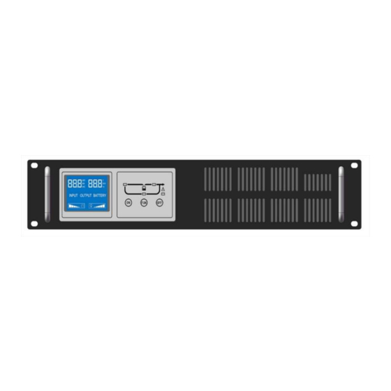
1.1 Spec. for Marks Marks and Meaning Attention Danger AC power DC power Protective Earth Conductor Protective Bonding Conductor Cycling Not Placed With Other Things Overload Battery On/Off Button 1.2 Front Panel JP5530 JP5530 JP5530 JP5530 6K/10K/15K/20K 6K/10K/15K/20K 6KL/10KL 6KL/10KL... -
Page 7: Real Panel
JP5530 RM6K/10K JP5530 RM15K/20K 1.3 Rear Panel JP5530 6K JP5530 10K... - Page 8 JP5530 6KL JP5530 10KL JP5530 15/20K...
- Page 9 JP5530 RM6K/10K JP5530 RM15K/20K ① interface for computer ② socket ③ fan ④ parallel card board (parallel card is optional) ⑤ switch for input ⑥ cover panel for maintenance switch(maintenance switch is optional) ⑦ terminal board ⑧ bracket for cable ⑨...
-
Page 10: Spec For Product
1.4 Specification When input voltage is 187V with rated full load, and charger works fully, UPS can have the maximum current. Load of the high altitude=rated power ×Rating factor(correspond to altitude) Altitude 1000 1500 2000 2500 3000 3500 4000 4500 5000 Rating 100%... -
Page 11: Installation
Note: If UPS are used when the altitude is above 1000m, must use Rating Factor to calculate, please read above table. Danger: Please cut off the switch of mains before installation, if UPS are long back up type, cut off the input of battery. Note: 1.Following must be operated by the professional staff 2. -
Page 12: Ups Connection
Model JP5530 JP5530 JP5530 JP5530 JP5530 JP5530 6K/RM6K 6KL/RM6KL 10K/RM10K 10KL/RM10K 15K/RM15K 20K/RM20K 10AWG 10AWG 8AWG 8AWG 6AWG 6AWG (6mm (6mm (10mm (10mm (25mm (25mm 10AWG 10AWG 8AWG 8AWG 6AWG 6AWG (25mm (25mm (6mm (6mm (10mm (10mm 10AWG 10AWG 8AWG 8AWG 6AWG 6AWG... - Page 13 Danger: when connect the cable, make sure the input/output cable connect the terminal fasten Terminal for UPS: JP5530 6KL/JP5530 6K JP5530 10KL/JP5530 10K 7. Fix the cover-plate with screws again. 8. Connect wires and get mains, then turn on the Input Protection Breaker, and UPS will be power-on.
-
Page 14: Installation For External Battery
2.4 External Battery Installation of Long-backup Type JP5530 6-20K Long-backup type apply 16 PCS of 12V batteries (192VDC) in series into one group and several groups can be in parallel. Please operate as following steps, otherwise, it may occur electric shock: 1. -
Page 15: Connection To The Computer
2.5 Connect UPS to the computer socket Socket o f computer: RS232 or USB, will connect the UPS to the monitor. 1 .Connect the RS232 or USB to the socket of computer 2. Connect the RS232 or USB to the socket of UPS The feet bitmap of computer port on UPS as following:... -
Page 16: Parallel(Optional)
2.6 Parallel card (optional) 1. Introduction N+X is the most stable construction for supplying power, N means minimum quantity of UPS needed, X means quantity of UPS parallel, when X becomes larger, the system will be more stable. 3pcs of UPS can be in parallel with parallel cards and cables in this range. - Page 17 1) The difference of each wire which connects block and loads must be less than 20% if the distance between loads and every paralleled UPS is less than 20 meters. 2) The difference of each wire which connects block and loads must be less than 10% if the distance between loads and every paralleled UPS is more than 20 meters.
- Page 18 3. Advantage of parallel Parallel can improve stability of UPS, when each UPS makes fault, the others still can work, and each UPS need maintenance switch by hand. 4. Operation 1)Follow the operation of single UPS. 2)Start UPS in parallel. Start UPS when mains on: start any one of the UPS, the other UPS will start working and transfer to inverter.
-
Page 19: Installation For Snmp(Optional)
2.7 Installation of SNMP (optional) Install SNMP on the above position of the real panel 1. Take off the board 2. Install SNMP card 3. Fix it using screws AS400 card (optional) Install AS400 card to the socket, the position as below: meaning PIN1 Break over: UPS fault... -
Page 20: Epo
2.8 EPO EPO (Emergent Power Off ) ,is on the real panel of UPS, is green terminal. ① 1-2 Close, UPS shut off immediately 3-4 Doesn’t work... -
Page 21: Maintenance Switch (Optional)
②、 1-2 Connect together, keep this status 3-4 Open,UPS shut off immediately 2.9 Maintenance Switch To realise online service of UPS following picture, no matter mains, battery, or bypass mode, internal sections of UPS have power, maintenance switch can let the UPS be away from the mains. -
Page 22: Dust Screen (Optional)
2.10 Dust screen (optional) Using dust screen can avoid the dust; in this wan UPS can be saved without dust. Installation of the dust screen as below: 1. Remove front panel 2. Install dust screen 3. Install front panel 2.11 Isolated transformer box (optional) Isolated transformer make the current more balance, user can select it on the output. -
Page 23: 3、Display Panel
3、 Display Panel 1#~10# LED : 1# fault: Flash when UPS fault, it is red 2#~6# load/battery capacity:under the mains mode means load, at the battery mode means battery capacity. 7# bypass:orange 8# mains:green 9# inverter:green 10# battery:orange 11#load capacity From right to left 6#→2#, the more LED flash, less load capacity 12# battery capacity... - Page 24 Button: 13# functional button:loudspeaker mute(press more than 2 seconds at bypass or battery mode) ;battery check(press more than 2 seconds at mains mode) 。 14# start/shut off UPS: LCD panel 1#-5# LED : 1# mains:green 2# bypass:orange 3# battery:orange 4# inverter:green 5# fault:red...
- Page 25 load/battery capacity: From left to right, the load increase From right to left, battery capacity increase 6# start UPS:Start UPS or “increase” when set the parameter 7# function button: Adjust the parameter (adjust BUS voltage, inverter output voltage and change screen to the next page) 8# shut off UPS:Shut off UPS or “decrease”...
-
Page 26: O P E R A T I O N
4、Operation 4.1 Start UPS on LED Panel Note: Even if the battery already charged, however it will consume during transportation, so charge the battery more than 12 hours when use UPS at the first time LED status : flash not flash Start UPS when the mains supply Press button more than 1 second, UPS will start and check itself, at this time, LED for load/battery capacity will flashes, and shut off... -
Page 27: Shut Off Ups On Led Panel
Loads will be supplied power by battery. Start UPS without mains, when connect with batteries Press the button more than 1 second, UPS will start After starting UPS, led for battery will flash, led for mains will shut off, load of the UPS will be supplied by the battery. (battery mode)... -
Page 28: Start Ups On Lcd Panel
UPS will have bypass output after shutting off the UPS, following is the picture. ON/OFF (bypass working mode) When UPS work at the bypass mode, led flashed, the buzzer alarm every 2 mints, press “loudspeaker mute” more than 2 seconds, if not need output, disconnect mains. -
Page 29: Shut Off Ups On Lcd Panel
Note: if the mains abnormal, UPS will work at the mode of battery. load will be supplied power by batteries Start UPS with DC Press the button more than 1 second, UPS will start After starting, battery light flashes, mains light will be off, load will be supplied power by the battery. -
Page 30: 5、Ba Tt Ery
After shutting off, UPS still have bypass output, LED indication as below: (bypass working mode) At the bypass mode, bypass light flashes, buzzer will alarm every 2 mints. Disconnect the mains if the UPS do not need output. 5、Maintenance of the battery UPS will charge the battery all the time. -
Page 31: M A I N T E N A N C E
6、Maintenance If the light flash or the buzzer alarm, that means something is wrong. (LED panel) Fault Reason solution Check that UPS is not overload, the temperature High in the room is not high. Shut off the 1#&6# flash, UPS for 10 mints and then restart, if in this temperature buzzer alarm way fail, please contact your supplier. -
Page 32: 7、Lights On Led/Lcd Panel
Time Press the button for more than 1 second pressing button is too short UPS does not press the connect the connect the battery, if the battery voltage is low, battery or start button, UPS will first of all charge the battery and then start the ups with not start UPS. - Page 33 Bypass mode Alarm every 2 ↑ ↑ ↑ ↑ ● ● ● mints Overload, don’t ● Alarm two ● ● ● ● ● ● transfer to times every 1 bypass seconds Overload and Alarm two ● ● ● ● ● ●...
- Page 34 Fault Code displays on LCD Panel E1: Fan fault E2: Can not read the model E3: Power board fault E4: Address of the module is the same E5: Don’t meet the requirement of starting UPS E6: Over charging the battery E7:...
- Page 35 Fault code display Common fault and handle (E 01) Reason: Fan fault Check: check whether fan is normal (E 02) Reason:Can not indentify the ups model(it will show this fault code only after replace main control board) Check: Generally speaking, restart after shut down (E 05) Reason: Don’...