Table of Contents
Advertisement
Quick Links
What's in the box?
In addition to this guide, the package includes the following
items:
I-7565M-HS
Related Information
I-7565M-HS User Manual
http://ftp.icpdas.com/pub/cd/fieldbus_cd/can/converter/i-7565
m-hs/manual
I-7565M-HS Website
http://www.icpdas.com/root/product/solutions/industrial_comm
unication/fieldbus/can_bus/converter/i-7565m-hs.html
ICP DAS Website
http://www.icpdas.com/
Copyright © 2018 ICP DAS Co., Ltd. All Rights Reserved.
Quick Start for
Dec 2018, Version 1.0.1
Screw Driver
(1C016)
E -mail:
I-7565M-HS
USB cable
(CA-USB15)
service@icpdas.com
1
Advertisement
Table of Contents

Subscribe to Our Youtube Channel
Related Manuals for ICP DAS USA I-7565M-HS


Summary of Contents for ICP DAS USA I-7565M-HS
- Page 1 In addition to this guide, the package includes the following items: Screw Driver USB cable I-7565M-HS (1C016) (CA-USB15) Related Information I-7565M-HS User Manual http://ftp.icpdas.com/pub/cd/fieldbus_cd/can/converter/i-7565 m-hs/manual I-7565M-HS Website http://www.icpdas.com/root/product/solutions/industrial_comm unication/fieldbus/can_bus/converter/i-7565m-hs.html ICP DAS Website http://www.icpdas.com/ Copyright © 2018 ICP DAS Co., Ltd. All Rights Reserved.
- Page 2 ----------------------------------------------------------------------- Hardware Installation Before using I-7565M-HS device, some things must be done. Step 1: Prepare one I-7565M-HS device Step 2: Determine if the terminal resistor is needed or Check the application structure, and determine if the terminal resistor is needed or not. You can find it at the position as follows.
- Page 3 Generally, if your application is as follows, we recommend you to enable the terminal resistor. If your application is like the structure as follows, the terminal resistor is not needed. Copyright © 2018 ICP DAS Co., Ltd. All Rights Reserved. E -mail: service@icpdas.com...
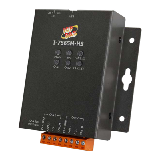
- Page 4 Step 4: Connect the CAN port and USB port of the I-7565M-HS. The pin assignment and wire connection are as follows. When finished, run your application with the I-7565M-HS. Copyright © 2018 ICP DAS Co., Ltd. All Rights Reserved. E -mail:...
- Page 5 Step 2: Setting up the I-7565M-HS module 1. Connect the PC available USB port with the USB port of the I-7565M-HS device. Users can find the communication cable (CA-USB15) in the product box. 2. Execute the I-7565-HS Utility tool.
- Page 6 Step 3: Connect to I-7565M-HS module When executing the Utility, the tool will try to scan all the necessary I-7565M-HS modules and list all scanned module information on “Module Name” location of the Utility “Connect” frame. User can re-connect to re-scan the newer inserted I-7565M-HS module.
- Page 7 2: Select the necessary I-7565M-HS module. 3: On the “CAN Port Enable” and “CAN1/CAN2 Baud Rate” location, user can set the CAN Bus, and other prarameters. The detail functions of these parameters are list below. [CAN Port Enable] “Port Enable”: Enable/Disable the CAN1/CAN2 port.
- Page 8 Step 4: Send, receive CAN messages By using the I-7565-HS Utiltiy tool, user can send and receive CAN messages via the I-7565M-HS devices. Send CAN messages and check received CAN messages Copyright © 2018 ICP DAS Co., Ltd. All Rights Reserved.
Need help?
Do you have a question about the I-7565M-HS and is the answer not in the manual?
Questions and answers