
Related Manuals for FLIR PatrolIR PTZ


Summary of Contents for FLIR PatrolIR PTZ
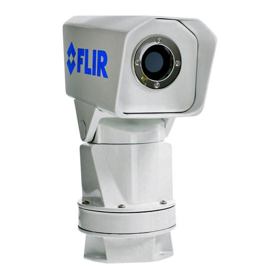
- Page 1 PatrolIR PTZ Pan and Tilt Operator’s Manual P a t r o l I R P T Z Pan and Tilt Operator’s Manual Document # 427-0001-00-11 Version 110, June 2008...
- Page 2 © FLIR Systems, Inc., 2008. All rights reserved worldwide. No parts of this manual, in whole or in part, may be copied, photocopied, translated, or transmitted to any electronic medium or machine readable form without the prior written permission of FLIR Systems, Inc.
-
Page 3: Table Of Contents
Warnings and Cautions Introduction Getting Started Caring for your PatrolIR PTZ Optional Accessories Technical Data Mounting Templates Infrared Technology 427-0001-00-11, version 110 06/08... - Page 5 PatrolIR PTZ Pan and Tilt Operator’s Manual Table of Contents 1 Warnings and Cautions 2 Introduction 3 Getting Started 3.1 Parts List ................5 3.2 Operational Overview ............... 6 3.3 Installation ................7 3.3.1 Camera Mounting ............7 3.3.2 Fuse and Joystick Control Unit Mounting ......10 3.4 Using your PatrolIR PTZ ............
- Page 6 06/08 427-0001-00-11, version 110...
-
Page 7: Warnings And Cautions
Minimize display viewing while driving. Viewing the display may distract the driver from looking ahead and may result in an accident. The PatrolIR PTZ thermal imaging system should not be used as a substitution for head lamps or head lamp assisted human vision during vehicle operation. - Page 8 1 – Warnings and Cautions Caution! The PatrolIR PTZ thermal imaging system is not intended to be used as the primary navigation system. The PatrolIR PTZ should not to be used as a substitution for head lamps or head lamp assisted human vision during vehicle operation.
-
Page 9: Introduction
It is also available with PAL output, the same format used on common televisions and VCR video input in Europe. The PatrolIR PTZ features a wide field of view and is capable of providing an image even in absolute darkness. - Page 10 2 – Introduction Figure 2-1: PatrolIR PTZ Makes the Difference The upper image represents what the human eye sees looking at a camouflaged subject in shady brush. The lower image is an infrared thermal picture taken at the same moment as the visible image above.
-
Page 11: Getting Started
Getting Started 3.1 Parts List The PatrolIR PTZ camera and its accessories are delivered in a box which contains the items below. Description FLIR PN PatrolIR PTZ camera white color, NTSC 427-0019-01-00 with attached 18’ cable and wired Joystick Control Unit... -
Page 12: Operational Overview
3 – Getting Started 3.2 Operational Overview The PatrolIR PTZ is easy to install and operate. The system operates on 12 volts DC and there are no camera adjustments. The thermal imaging camera inside the PatrolIR PTZ is completely sealed and extremely rugged. -
Page 13: Installation
3 – Getting Started 3.3 Installation Caution! The PatrolIR PTZ should be installed by a trained professional. Incorrect installation could void your warranty. It is strongly recommended that you DO NOT separate the Camera from its base during installation. 3.3.1 Camera Mounting Caution! The PatrolIR PTZ is intended to be mounted above the mounting plane. - Page 14 By rotating the camera, each of the four mounting screws can be tightened. Your PatrolIR PTZ can be installed with machine Figure 3-3: Accessing the mounting screws screws, washers, lock washers, and hex nuts as described below.
- Page 15 3 – Getting Started 5.1mm (0.20”) for machine screw 62.7mm (2.47”) 62.7mm (2.47”) clocking-pin hole 1/4” x 20 mounting hole This drawing is not to scale Figure 3-4: Base Mounting Template for the Camera socket head machine screws four places mounting surface gasket...
-
Page 16: Fuse And Joystick Control Unit Mounting
Caution! Changing the wiring configuration of the PatrolIR PTZ or attempting to utilize controllers or wiring harnesses other than those supplied by FLIR may cause permanent damage to the unit and may void the warranty. Caution! Do not connect the camera to anything other than 12 VDC power. - Page 17 3 – Getting Started 60.325mm (2.375”) CUT for JCU 31.75mm (1.25”) 34.3mm (1.35”) 139.7mm 132mm (5.50”) (5.20”) This drawing is not to scale DRILL 6.4mm (0.25”) for threaded stud six places 31.75mm (1.25”) Figure 3-6: Joystick Control Unit mounting template nuts and washers (4 each) mounting studs (2)
- Page 18 3 – Getting Started Table 3-1: JCU Terminal block connections Terminal Signal name and source Wire color block location +12VDC IN—from main electrical power cable 12VDC RETURN—from main electrical power cable Black +12VDC OUT—to camera control/power cable 12VDC OUT RETURN—to camera control/power cable Black -RS422 OUT—to camera control/power cable Green...
- Page 19 3 – Getting Started Step 8 Connect the 12 VDC power and return wires from your fuse panel to the JCU wiring harness. Wire must be 16 gage. Note: Depending on your JCU mounting location you may want to connect the ground wire and power cables either before or after installing the JCU.
-
Page 20: Using Your Patrolir Ptz
It should be used in conjunction with other navigation aids and a primary manual navigation system. The PatrolIR PTZ is easy to use, but you should take a moment to carefully read this section so you fully understand how to use the controls and what you are seeing on your display. - Page 21 3 – Getting Started The choice of video image mode is strictly a personal preference and you should experiment to find your preferred mode. Joystick—move to the left or right to rotate the camera; forward or back to raise or lower the camera. Make sure that the camera power is switched on at your main power panel.
- Page 22 Look for variations or anomalies in scenes that you think would normally be the same temperature. As you experiment with your PatrolIR PTZ, you will see your world in a different light. Consider every object you view in terms of how it will look “thermally”...
-
Page 23: Caring For Your Patrolir Ptz
Caring for your PatrolIR PTZ 4.1 Troubleshooting Caution! Do not open the camera body for any reason. Disassembly of the camera (including removal of the cover) can cause permanent damage and will void the warranty. If the camera will not produce an image, check the inline fuse and the fuse panel. -
Page 24: Replacing The Fuses
Caution! Replace system fuses with the same value and type provided at the time of purchase. Using fuse values other than the ones supplied by FLIR Systems, Inc. may cause permanent damage to the unit and may void the warranty. -
Page 25: Cleaning
4 – Caring for your PatrolIR PTZ 4.2.1 Cleaning Caution! The camera window has an anti-reflective coating and should be cleaned only with low pressure fresh water and a lens cloth. Caution! Improper care of the camera window can cause damage to the anti-reflective coating, degrade the camera’s performance, and void the... -
Page 27: Optional Accessories
Optional Accessories 5.1 Optional Extension Cables FLIR Systems makes available a family of extension cables and remote video/control station kits. The part numbers are as follows: Description FLIR PN 7.6 m (25’) Extension Cable for Pan & Pan Tilt 308-0129-00... -
Page 29: Technical Data
Technical Data 6.1 Performance Specifications Thermal Imaging Performance Sensor type 320 x 240 uncooled microbolometer Field of view 36° h x 27° v 8 - 14 μ Spectral band Outputs Video NTSC or PAL Connector types BNC at primary cable end Power Power requirements 12 VDC... -
Page 31: Mounting Templates
Mounting Templates 7.1 Camera Mounting Template. 4X on 88.9 mm (3.50") bolt circle 5.1 mm (0.20") for machine screw 62.7mm (2.47”) clocking-pin hole 62.7mm (2.47”) 1/4” x 20 mounting hole For installation purposes, a tear out version of this page is located at the very back of this manual. -
Page 33: Joystick Control Unit Mounting Template
7 – Mounting Templates 7.2 Joystick Control Unit Mounting Template. 60.325mm (2.375”) CUT for JCU 31.75mm (1.25”) 34.3mm (1.35”) 139.7mm 132mm 5.50” (5.20”) DRILL 6.4 mm (0.25”) for threaded stud six places 31.75 mm (1.25”) For installation purposes, a tear out version of this page is located at the very back of this manual. -
Page 35: Infrared Technology
Infrared Technology 8.1 History of Infrared Just over 200 years ago the existence of the infrared portion of the electromagnetic spectrum wasn't even suspected. The original significance of the infrared spectrum, or simply ‘the infrared’ as it is often called, as a form of heat radiation is perhaps less obvious today than it was at the time of its discovery by Herschel in 1800. - Page 36 8 – Infrared Technology As the blackened thermometer was moved slowly along the colors of the spectrum, the temperature readings showed a steady increase from the violet end to the red end. This was not entirely unexpected, since the Italian researcher, Landriani, in a similar experiment in 1777 had observed much the same effect.
- Page 37 8 – Infrared Technology true only until 1830, when the Italian investigator, Melloni, made his great discovery that naturally occurring rock salt (NaCl)—which was available in large enough natural crystals to be made into lenses and prisms—is remarkably transparent to the infrared. The result was that rock salt became the principal infrared optical material, and remained so for the next hundred years, until the art of synthetic crystal growing was mastered in the 1930’s.
- Page 38 8 – Infrared Technology Figure 8-4: Samuel P. Langley (1834–1906) The improvement of infrared-detector sensitivity progressed slowly. Another major breakthrough, made by Langley in 1880, was the invention of the bolometer. This consisted of a thin blackened strip of platinum connected in one arm of a Wheatstone bridge circuit upon which the infrared radiation was focused and to which a sensitive galvanometer responded.
- Page 39 8 – Infrared Technology converter and the photon detector. At first, the image converter received the greatest attention by the military, because it enabled an observer for the first time in history to literally ‘see in the dark’. However, the sensitivity of the image converter was limited to the near infrared wavelengths, and the most interesting military targets (i.e.
-
Page 40: How Do Infrared Cameras Work
8 – Infrared Technology 8.2 How do Infrared Cameras Work? Infrared energy is part of a complete range of radiation called the electromagnetic spectrum. The electromagnetic spectrum includes gamma rays, X-rays, ultraviolet, visible, infrared, microwaves (RADAR), and radio waves. The only difference between these different types of radiation is their wavelength or frequency. - Page 41 The infrared imager converts this energy into an image that we can interpret. Several detector technologies exist; the sensor in the PatrolIR PTZ is of the latest solid state design, offering long life and fully automatic image optimization (contrast and gain).
- Page 43 4X on 88.9 mm (3.50") bolt circle 5.1 mm (0.20") for machine screw 62.7mm (2.47”) clocking-pin hole 62.7mm (2.47”) 1/4” x 20 mounting hole Full size PatrolIR PTZ Mounting Template...
- Page 45 60.325mm (2.375”) CUT for JCU 31.75mm (1.25”) 34.3mm (1.35”) 135.9 mm 34.3mm 132mm (5.53") (1.35”) (5.20”) DRILL 6.4 mm (0.25”) for threaded stud six places 31.75 mm (1.25”) Full size Joystick Control Unit Mounting Template...
- Page 48 www.flir.com...
Need help?
Do you have a question about the PatrolIR PTZ and is the answer not in the manual?
Questions and answers