Advertisement
Quick Links
Advertisement

Subscribe to Our Youtube Channel
Related Manuals for AutomationDirect CLICK Series


Summary of Contents for AutomationDirect CLICK Series
- Page 1 Manual Number: C0-USER-M...
- Page 2 This publication may contain references to products produced and/or offered by other companies. The product and company names may be trademarked and are the sole property of their respective owners. AutomationDirect disclaims any proprietary interest in the marks and names of others.
- Page 3 770-844-4200 en Estados Unidos. Esta publicación está basada en la información disponible al momento de impresión. En Automationdirect. com nos esforzamos constantemente para mejorar nuestros productos y servicios, así que nos reservamos el derecho de hacer cambios al producto y/o a las publicaciones en cualquier momento sin notificación y sin...
- Page 4 Nulle partie de ce manuel ne doit être copiée, reproduite ou transmise de quelque façon que ce soit sans le consentement préalable écrit de la société Automationdirect.com ® Incorporated. AutomationDirect conserve les droits exclusifs à l’égard de tous les renseignements contenus dans le présent document.
- Page 5 CLICK PLC User Manual Please include the Manual Number and the Manual Issue, both shown below, when communicating with Technical Support regarding this publication. Manual Number: C0-USER-M Issue: 6th Edition, Rev. G Issue Date: 2/2020 Publication History Issue Date Description of Changes 1st Edition 5/08 Original...
- Page 6 able of onTenTs Publication History Table of Contents Chapter 1 - Getting Started Introduction ........................2 Conventions Used ......................3 Before you begin......................4 Step 1: Install Programming Software................5 Step 2: Launch Programming Software ................6 Step 3: Create a Project ....................8 Step 4: Compile and Save Project ................14 Step 5: Apply Power ....................15 Step 6: Establish PC to PLC Communications.............16 Step 7: Write Project into PLC ..................24...
- Page 7 Table of Contents Standard PLC Units ....................2–4 Built-in I/O (Standard PLC Units) ................2–4 Analog PLC Units ..................... 2–5 Built-in I/O (Analog PLC Units) ................. 2–5 Ethernet Basic PLC Units ................... 2–6 Built-in I/O (Ethernet Basic PLC Units) ..............2–6 Ethernet Standard PLC Units ..................
- Page 8 Table of Contents Power Budget Example ..................2–25 Power Budgeting using the CLICK Programming Software ........2–25 General Specifications ..................... 2–26 General Specifications (all CLICK PLC units) ............2–26 PLC Unit Specifications .................... 2–27 Common Specifications ..................2–27 PLC LED Status Indicators ..................2–29 Memory Map ......................
- Page 9 Table of Contents Ethernet Analog PLC Unit Specifications ..............2–76 C0-12DD1E-D – 4 DC Input (Sink/Source)/4 Sinking DC Output ......2–76 2 Analog Voltage/Current Input 2 Analog Voltage/Current Output Micro PLC ............2–76 C0-12DD2E-D – 4 DC Input (Sink/Source)/4 Sourcing DC Output; ......2–79 2 Analog Voltage/Current Input 2 Analog Voltage/Current Output Micro PLC ............
- Page 10 Table of Contents I/O Module Specifications ..................2–112 I/O Terminal Block Specifications for CPUs and I/O Modules ........ 2–112 LED Indicators ...................... 2–113 C0-08SIM – 8-Point Toggle Switch Input Module ..........2–114 C0-08ND3 – 8-Point Sink/Source DC Input Module ..........2–115 C0-08ND3-1 –...
- Page 11 Table of Contents C0-01AC Power Supply ..................2–148 PSP24-DC12-1 DC-DC Converter ................. 2–148 Accessories ......................2–149 Chapter 3 - Installation and Wiring Safety Guidelines ....................... 3–2 Plan for Safety ......................3–2 Three Levels of Protection ..................3–3 Orderly System Shutdown ..................3–3 System Power Disconnect ..................
- Page 12 Table of Contents Planning the I/O Wiring Routes ................3–20 Wiring I/O Modules ....................3–21 ZIPLink Wiring System Compatibility Matrix for CLICK PLCs........3–22 I/O Wiring Checklist ....................3–25 System Wiring Strategies ..................3–26 PLC Isolation Boundaries ..................3–26 Powering I/O Circuits ..................... 3–27 Sinking/Sourcing Concepts ..................
- Page 13 Table of Contents Port 2 (RS-232) – Modbus RTU or ASCII ..............4–10 Port 3 (RS-485 – Modbus RTU or ASCII) ............... 4–11 W-1: Com Port 1 & 2 (RS-232) Wiring ..............4–12 W-2: Com Port 1 (Ethernet) Wiring ................ 4–17 W-3: Com Port 3 Wiring ..................
- Page 14 Table of Contents Power Supply Troubleshooting ................. 6–5 The input voltage measures less than 20VDC ............6–5 The input voltage measures greater than 28VDC ............. 6–5 How to check the power budget ................6–5 I/O Module Troubleshooting ..................6–6 Input Module Troubleshooting ................. 6–6 Output Module Troubleshooting ................
- Page 15 hapter hapter hapter ettinG tarted In This Chapter... Introduction ......................1–2 Conventions Used ..................... 1–3 Before you begin...................... 1–4 Step 1: Install Programming Software..............1–5 Step 2: Launch Programming Software ..............1–6 Step 3: Create a Project .................... 1–8 Step 4: Compile and Save Project ................
- Page 16 Introduction Purpose of this Manual Thank you for purchasing the AutomationDirect CLICK PLC family of products. This hardware user manual provides information that will help you install, set up, program, troubleshoot, and maintain your CLICK PLC system. The manual includes information that is critical to the safety of the personnel who will install and use the PLC, and to the machinery, processes, and equipment controlled by the PLC.
- Page 17 Chapter 1: Getting Started Conventions Used WARNING: When you see the exclamation point icon in the left-hand margin, the paragraph to its immediate right will be a warning. This information could prevent injury, loss of property, or even death in extreme cases. Any warning in this manual should be regarded as critical information that should be read in its entirety.
- Page 18 One of the cables shown below: C0-PGMSW Ethernet Cat5 Cable PC with USB port to Panel Programming Cable Assembly Not available from ADC. EA-MG-PGM-CBL CD-ROM or Free download @ http://support.automationdirect.com/ Screwdriver products/clickplcs.html TW-SD-MSL-2 PC Programming Cable D2-DSCBL AC Power Cord Wire Strippers Hookup Wire DN-WS PC requires RS-232 port.
- Page 19 1. If you have the programming software on CD, insert the CD in the computer drive and follow the instructions. Otherwise, download the free CLICK Programming Software, C0-PGMSW, from the following Automationdirect.com web site: http://support.automationdirect.com/products/clickplcs.html 2. Unzip the downloaded ZIP file.
- Page 20 Double click the desktop CLICK icon or, from the PC’s Start menu, slide the mouse pointer through the menus (Start > All Programs > AutomationDirect > CLICK Ver 2.50 > CLICK Programming Software) and click the CLICK Programming Software selection or, simply click the icon on the Quick Launch bar.
- Page 21 Chapter 1: Getting Started Step 2: Launch Programming Software (cont’d) The Main Window is divided into Menus, Toolbars, and Windows that work together to make project development as simple as possible. See the software’s online help for additional details. Click on the “Start a new project” graphic in the Startup dialog box. The Select a CPU Module window opens.
- Page 22 Chapter 1: Getting Started Step 3: Create a Project In this step, the project shown below is created by entering the ladder logic program in the order that follows. Rung #1 Place the Box Cursor on the first position on Rung #1, as shown below.
- Page 23 Chapter 1: Getting Started Step 3: Create a Project (cont’d) Rung #1 (cont’d) The Line creation tool is used to add a normally open contact in parallel with the C1 contact. Click on the Line creation tool icon located on the Edit toolbar. A blue line will appear, showing the direction of the new line.
- Page 24 Chapter 1: Getting Started Step 3: Create a Project (cont’d) Rung #1 (cont’d) Next, click on the Reset Line Mode icon located on the Edit toolbar (Esc key has the same function as the Reset Line Mode). The Box Cursor will move to the newly created path. If not, position the Box Cursor over the new path to get ready for the next instruction.
- Page 25 Chapter 1: Getting Started Step 3: Create a Project (cont’d) Rung #1 (cont’d) From the Instruction List, click & drag a Contact (NO) into the Box Cursor. Enter C2 into the Bit Memory Address text box of the Contact Normally Open dialog box that pops up and click OK.
- Page 26 Chapter 1: Getting Started Step 3: Create a Project (cont’d) Rung #2 Place the Box Cursor at the beginning of Rung #2. From the Instruction List, click and drag a Contact (NO) into this box. Enter T1 into the Bit Memory Address text box of the Contact Normally Open dialog box that pops up.
- Page 27 Chapter 1: Getting Started Step 3: Create a Project (cont’d) Program Execution The following is an explanation of how the CLICK PLC executes the ladder logic program that was just entered. The CLICK PLC executes the ladder logic program instructions, starting with Rung #1, from left to right, and then proceeds to execute the next rung in the same fashion, carrying on through all of the rungs in sequential order.
- Page 28 Chapter 1: Getting Started Step 4: Compile and Save Project Syntax Check (Compile) Next, you will need to compile the ladder logic program. Compiling the program is done with the Syntax Check function. The ladder program is checked for problems and other conditions that may prevent the ladder program from executing correctly.
- Page 29 CLICK PLC unit. Wire the 24 VDC output from a CLICK power supply, or a properly sized and rated 24 VDC power supply such as AutomationDirect’s RHINO series, to the bottom terminal block (See Chapter 2: Specifications for power supply specifications.) EITHER Using a CLICK 24 VDC Power Supply.
- Page 30 Chapter 1: Getting Started Step 6: Establish PC to PLC Communications Next, connect a personal computer (PC) to Port 1 or Port 2 on the CLICK PLC unit. You can use one of the following communication ports on the CLICK PLC unit for programming. C0-01DD1-D C0-01DD1-D C0-11DD1E-D...
- Page 31 Using an RS-232 port for Programming EITHER If a USB port is available on the PC, then use an AutomationDirect USB to RS232 PC to Panel Programming Cable Assembly (P/N - EA-MG-PGM-CBL) to connect between the USB port on the PC and the RJ12 connector on the PLC’s Port 1.
- Page 32 Chapter 1: Getting Started Step 6: Establish PC to PLC communications (cont’d) Once we have a communications cable connected between a port on the PC and PORT1 on the CLICK PLC, we need to select the PC COM port that is connected to the CLICK PLC.
- Page 33 Chapter 1: Getting Started Step 6: Establish PC to PLC Communications, (cont’d) NOTE: If using the USB to RS232 converter, and you are not sure to which PC COM Port the USB port is assigned, click the Detail... button next to the COM Port drop down list to identify it.
- Page 34 Chapter 1: Getting Started Step 6: Establish PC to PLC Communications, (cont’d) Using Ethernet Port for Programming You can connect your PC to the CLICK PLC via an Ethernet switch/hub or directly to the Ethernet port. You can use a straight or crossover Ethernet cable. Once we have communications cable(s) connected between the Ethernet port on the CLICK PLC and the Ethernet port on the PC, we are ready to connect the...
- Page 35 Chapter 1: Getting Started Step 6: Establish PC to PLC Communications, (cont’d) Select Ethernet as the Port Type. Select the network adapter that you want to connect to the CLICK PLC, if you have more than one network adapter on your PC. The CLICK programming software automatically scans the CLICK PLC units in the LAN connected to the network adapter and displays them in the list as shown below.
- Page 36 Chapter 1: Getting Started Step 6: Establish PC to PLC Communications, (cont’d) To match the subnet setup of the CLICK PLC to the subnet that the your PC locates in, select the CLICK PLC unit in the list and click the Edit button under the list.
- Page 37 Chapter 1: Getting Started Step 6: Establish PC to PLC Communications, (cont’d) If you are trying to connect the CLICK Programming Software to a new CLICK PLC or an older CLICK PLC that was reset to the factory default, you will see the following pop-up message once communication has been established with the CLICK PLC.
- Page 38 Chapter 1: Getting Started Step 7: Write Project into PLC The next step is used to transfer the project that was created into the CLICK PLC. From the PLC drop down menu, select Write Project into PLC as shown to the right, or click on the Write Project into PLC icon located on the PLC Toolbar.
- Page 39 Chapter 1: Getting Started Step 8: Place PLC in RUN Mode The next step is to place the CLICK PLC into its Run mode so that the ladder logic program will execute. From the PLC drop down menu, select PLC Modes... as shown to the right, or click on the PLC Modes...
- Page 40 Chapter 1: Getting Started Step 9: Test Project using Data View Monitor In this next step, use the Data View Monitor to test the ladder logic program by manually overriding the status of the internal C1 bit that was programmed. The purpose of this will be to have the C1 bit enable Timer T1.
- Page 41 Chapter 1: Getting Started Step 10: Y001 Output On? CLICK PLC output Y001 (labeled Y1 on the PLC unit) will turn on 5 seconds after you write the ON state to the C1 bit using Data View in the Edit mode. Y001 If you missed viewing the transition of the Y001 status LED from OFF to ON, write an OFF state to the C1 bit and then an ON state in the Data View Monitor to do it again.
- Page 42 (b) “Programmable Controllers” on the top, lefthand topic bar for Video Filter list. Select (c) “CLICK series PLCs”. A page of CLICK specific videos will open. A search for CLICK (d) will pull up all the CLICK videos as well. The videos cover all aspects of the CLICK PLC, from an introductory video, to communications, and programming.
- Page 43 Chapter 1: Getting Started Interconnecting Automation Online Training Courses offered at- http://www.interconnectingautomation.com/onlinecourses Interconnecting Automation offers inexpensive subscription-based online training, including CLICK PLC training. Also, a CLICK PLC Trainer is available from this web site. CLICK PLC Hardware User Manual, 6th Edition, Rev. G – C0-USER-M 1–29...
- Page 44 hapter hapter hapter pecificationS In This Chapter... Overview of PLC System ................... 2–2 PLC Units ........................2–3 I/O Modules ......................2–10 Programming Software ................... 2–14 Data Types, Memory, and Numbering System ............2–15 PLC Operation ......................2–19 Power Budgeting ..................... 2–23 General Specifications .....................
- Page 45 Chapter 2: Specifications Overview of PLC System The CLICK PLC family of components is designed to combine practical PLC features in a compact and expandable design, with a simple-to-use philosophy. A powered CLICK PLC unit by itself can be used as a complete PLC system with built-in I/O points, or the system can be expanded with the addition of up to eight I/O modules.
- Page 46 Chapter 2: Specifications PLC Units All CLICK PLC units offer the same instruction set, and support all optional I/O modules. The six types of PLC units available are listed in the table below. Discrete I/O Analog I/O Communication Ports Battery RUN time PLC Types Backup...
- Page 47 Chapter 2: Specifications Standard PLC Units The Standard CLICK PLC units are available with different combinations of built-in I/O types (i.e. DC input/DC output, DC input/relay output, and AC input/relay output). They also have an RS-485 port for Modbus RTU and ASCII communications, and the battery backup feature which will retain the data in SRAM for 3 years.
- Page 48 Chapter 2: Specifications Analog PLC Units The Analog CLICK PLC units are available with different combinations of DC in, DC sinking, sourcing or relay out, and analog in and out. They also have an RS-485 port for Modbus RTU and ASCII communications, and the battery backup feature which will retain the data in SRAM for 3 years.
- Page 49 Chapter 2: Specifications Ethernet Basic PLC Units The Ethernet Basic CLICK PLC units are available with different combinations of built-in I/O types, e.g. DC input /DC output, DC input/relay output, and AC input/relay output. Four types of Ethernet Basic PLC units are available. PLC Mode C0-10DD1E-D C0-10D...
- Page 50 Chapter 2: Specifications Ethernet Standard PLC Units The Ethernet Standard CLICK PLC units are available with different combinations of built-in I/O types, e.g., DC input /DC output, DC input/relay output, and AC input/relay output. PLC Mode Switch C0-11DD1E-D C0-11D D1E- 8 Discrete Input Points...
- Page 51 Chapter 2: Specifications Ethernet Analog PLC Units The Ethernet Analog CLICK PLC units are available with different combinations of built-in I/O types, e.g., DC input /DC output, DC input/relay output, and AC input/relay output, and analog in and out. PLC Mode Switch C0-12DD1E-D C0-12D...
- Page 52 Chapter 2: Specifications Communication Ports The Basic CLICK PLC units have two built-in RS-232 serial communications ports. Standard and Analog PLC units also have an additional RS-485 port. All CLICK Ethernet PLC units have one built-in Ethernet communication port and one RS-232 serial communication port. Ethernet Standard and Ethernet Analog PLC units also have an additional RS-485 port.
- Page 53 Chapter 2: Specifications I/O Modules A variety of I/O modules is available for the CLICK PLC System. Up to 8 I/O modules can be connected to a CLICK PLC unit to expand the system I/O count and meet the needs of a specific application.
- Page 54 Chapter 2: Specifications Discrete Output Modules C0-08TD1 C0-08TD2 C0-16TD1 C0-16TD2 C0-08TA C0-04TRS C0-04TRS-10 Discrete Output Modules Voltage/Current Part Number Output Type Ratings C0-08TD1 8 DC (Sink) 3.3–27 VDC / 0.3 A C0-08TD2 8 DC (Source) 12–24 VDC / 0.3 A C0-16TD1 16 DC (Sink) 5–27 VDC / 0.1 A...
- Page 55 Chapter 2: Specifications Analog Input Modules Analog Input Modules C0-04AD-1 C0-04RTD C0-04AD-2 C0-04THM 0-20mA Pt, Cu, Ni, RES 0-10V J,K,E,R,S,T,B,N,C,mV External Part Analog Input Types Power R1– Number Required 4 channel, current C0-04AD-1 24VDC R2– (0–20 mA), 13-bit 4 channel, voltage C0-04AD-2 24VDC TC1+...
- Page 56 NOTE: It is not mandatory to use one of the above CLICK power supplies for the CLICK PLC system. A properly-sized and rated 24VDC power supply, such as some of those offered by Automationdirect.com, can also be used to power a CLICK PLC system.
- Page 57 Chapter 2: Specifications Programming Software The CLICK PLC Programming Software, which can be downloaded free from the Automationdirect.com web site (Downloads/Software), is designed to provide simple and fast application development of ladder logic programming. These are some of the features that help make this happen: •...
- Page 58 Chapter 2: Specifications Data Types, Memory, and Numbering System The following section explains how the CLICK PLC handles the available data types, memory addressing, and I/O numbering. Data Types The CLICK PLC supports the following data types. On the CLICK PLC programming software, each data type is indicated with a small icon.
- Page 59 Chapter 2: Specifications Memory Types The following is the list of the memory types that the CLICK PLC system supports. See the memory map later in this chapter. Data Memory Type Symbol Definition Type Icon Input Point The Discrete Input points are represented by the “X” symbol. Output Point The Discrete Output points are represented by the “Y”...
- Page 60 Chapter 2: Specifications Memory Types (cont’d) Pointer Addressing The CLICK PLC allows the use of Pointer Addressing for flexibility in programming. The Copy instruction supports Pointer Addressing in the single copy mode. The Pointer is always assigned as a DS memory type and is designated as a Pointer by placing the DS memory type in square brackets, such as [DS1].
- Page 61 Chapter 2: Specifications I/O Numbering System The CLICK PLC uses decimal numbers for the input (X) and output (Y) addressing. X 2 16 For example, address X216 means the 16 input point on the second module from the CPU module. X: Input Module I/O Point #...
- Page 62 Chapter 2: Specifications PLC Operation Introduction Achieving proper control of your equipment or process requires a thorough understanding of how the CLICK PLC controls all aspects of system operation. There are three main areas to understand before you create your application program: •...
- Page 63 Chapter 2: Specifications PLC Operating Modes Stop Mode Run/Stop C0-00DD1-D Mode Switch In Stop mode, the CLICK PLC does NOT execute the ladder logic program or update the output points. The primary use for Stop Mode is to enter or change a ladder logic program.
- Page 64 Chapter 2: Specifications Read Inputs The CLICK PLC reads the status of all inputs, then stores it in the image register. Input image register locations are designated with an X followed by a memory location. Image register data is used by the PLC when it solves the application program. Of course, an input may change after the PLC has just read the inputs.
- Page 65 Chapter 2: Specifications WARNING: Only authorized personnel fully familiar with all aspects of the application should make changes to the program. Make sure you thoroughly consider the impact of any changes to minimize the risk of personal injury or damage to equipment. Update System Control (SC) Relays and System Data (SD) Registers The CLICK PLC units have system memory locations that hold this information.
- Page 66 The CLICK PLC operates from a 24VDC power source. The 24VDC power source can be provided by an optional CLICK PLC unit power supply (C0-00AC or C0-01AC), or a standard industrial 24VDC power supply as offered by AutomationDirect. CLICK 24VDC Power Supply...
- Page 67 Chapter 2: Specifications Power Budget Calculation The following table shows the current consumption required for both the logic side and field side of the CLICK units. PLC Current Consumption (mA) I/O Module Current Consumption (mA) Power Budget External Power Budget External Part Number 24VDC...
- Page 68 Chapter 2: Specifications Power Budget Example Add the current consumption for each module in the system as shown in this Power Supply PLC Unit I/O Module example. (C0-01AC) (C0-00DD1-D) (C0-16ND3) I/O Module (C0-16TD1) Current Consumption (mA) Port 1 Port 2 Power Budget External Part Number...
- Page 69 Chapter 2: Specifications General Specifications General Specifications (all CLICK PLC units) The following general specifications apply to all CLICK PLC units, optional I/O modules, and optional power supply products. Please refer to the appropriate I/O temperature derating charts under both the PLC and I/O module specifications to determine best operating conditions based on the ambient temperature of your particular application.
- Page 70 C0-16TB C0-16TB Communication Port & Terminal AutomationDirect p/n C0-3TB AutomationDirect p/n C0-3TB Block Replacement 24VDC Power Terminal Block AutomationDirect p/n C0-4TB AutomationDirect p/n C0-4TB AutomationDirect p/n C0-4TB Replacement 2–27 CLICK PLC Hardware User Manual, 6th Edition, Rev. G – C0-USER-M...
- Page 71 User Error Log Memory Backup Super Capacitor + Battery Battery Backup Yes (battery part # D2-BAT-1) Calendar/Clock I/O Terminal Block Replacement AutomationDirect p/n C0-16TB Communication Port & Terminal AutomationDirect p/n AutomationDirect p/n C0-3TB Block Replacement C0-3TB 24VDC Power Terminal Block...
- Page 72 Chapter 2: Specifications PLC LED Status Indicators Basic CPUs Basic PLC POWER LED (Green) Power Good Power Failure RUN LED (Green) PLC Run Mode Initializing Blink System INPUT LEDs (Green) PLC Program Input True Mode Input False ERROR LED (RED) Self Diagnostic Error Self Diagnostic...
- Page 73 Chapter 2: Specifications PLC LED Status Indicators, (cont’d) Analog PLC POWER LED (Green) Analog PLCs Power Good Power Failure INPUT LEDs (Green) RUN LED (Green) C0-02DD1-D Input True PLC Run Mode Input False Initializing Blink System OUTPUT LEDs (Red) PLC Program Output True Mode Output False...
- Page 74 Chapter 2: Specifications PLC LED Status Indicators, (cont’d) Ethernet Standard PLC POWER LED (Green) Standard Ethernet PLC Standard Ethernet PLC Power Good Power Failure C0-11DD1E-D C0-11D D1E- RUN LED (Green) PLC Run Mode Initializing INPUT LEDs (Green) Blink R R R UN System X4 4 Input True...
- Page 75 Chapter 2: Specifications Memory Map All of the CLICK PLC units support the same memory map. The CLICK PLC uses decimal numbers for the memory addressing. See pages 2-15 and 2-16 for the definitions of each data type and memory type. Data Memory Type Symbol...
- Page 76 Chapter 2: Specifications CLICK Software PID Specifications PID Specifications PID maximum number of loops Required Memory 40 C bits, 15 DS registers, 25 DF registers Control Algorithm Position Control Loop Action Direct-acting or Reverse-acting Error Term Linear or Squared Error Dead band Configurable Proportional Gain 0.01–10000...
- Page 77 Chapter 2: Specifications CLICK PLC Hardware/Software Compatibility CLICK PLCs require a minimum software version of v2.50 for the PID function. The table below shows the most recent software and hardware versions required for access to the High- Speed input operation capability. CLICK PLC Features Software Compatibility Minimum CLICK Software Version CPU Type...
- Page 78 Chapter 2: Specifications Basic PLC Unit Specifications C0-00DD1-D – 8 DC Input/6 Sinking DC Output Micro PLC Built-in I/O Specifications - Inputs Wiring Diagram Inputs per Module 8 (Sink/Source) Operating Voltage Range C0-00DD1-D 24VDC 24VDC Input Voltage Range 21.6–26.4 VDC X1-2: Typ 5mA @ 24VDC Input Current X3-8: Typ 4mA @ 24VDC...
- Page 79 Chapter 2: Specifications C0-00DD1-D – 8 DC Input/6 Sinking DC Output Micro PLC (continued) Built-in I/O Specifications - Outputs Outputs per Module 6 (Sink) Operating Voltage Range 5–27 VDC Output Voltage Range 4–30 VDC C0-00DD1-D Temperature Derating Chart 0.1 A/point; C3: 0.4 A/common, Maximum Output Current C4: 0.2 A/common Minimum Output Current...
- Page 80 Chapter 2: Specifications C0-00DD2-D – 8 DC Input/6 Sourcing DC Output Micro PLC Built-in I/O Specifications - Inputs Wiring Diagram Inputs per Module 8 (Sink/Source) C0-00DD2-D Operating Voltage Range 24VDC 24VDC Input Voltage Range 21.6–26.4 VDC X1-2: Typ 5mA @ 24VDC Input Current X3-8: Typ 4mA @ 24VDC X1-2: 6.0 mA @ 26.4 VDC...
- Page 81 Chapter 2: Specifications C0-00DD2-D – 8 DC Input/6 Sourcing DC Output Micro PLC (continued) Built-in I/O Specifications - Outputs Outputs per Module 6 (Source) C0-00DD2-D Temperature Derating Chart Operating Voltage Range 24VDC Output Voltage Range 19.2–30 VDC Maximum Output Current 0.1 A/point , 0.6 A/common Outputs Minimum Output Current...
- Page 82 Chapter 2: Specifications C0-00DR-D – 8 DC Input/6 Relay Output Micro PLC Built-in I/O Specifications - Inputs Wiring Diagram Inputs per Module 8 (Sink/Source) Operating Voltage Range 24VDC C0-00DR-D 24VDC Input Voltage Range 21.6–26.4 VDC X1-2: Typ 5mA @ 24VDC Input Current X3-8: Typ 4mA @ 24VDC X1-2: 6.0 mA @ 26.4 VDC...
- Page 83 Chapter 2: Specifications C0-00DR-D – 8 DC Input/6 Relay Output Micro PLC (continued) Built-in I/O Specifications - Outputs C0-00DR-D Temperature Derating Chart Outputs per Module Operating Voltage Range 6–240 VAC (47–63 Hz), 6–27 VDC Output Voltage Range 5–264 VAC (47–63 Hz), 5–30 VDC Output Type Relay, form A (SPST) Outputs...
- Page 84 Chapter 2: Specifications C0-00AR-D – 8 AC Input/6 Relay Output Micro PLC Built-in I/O Specifications - Inputs Wiring Diagram Inputs per Module Operating Voltage Range 100–120 VAC C0-00AR-D Input Voltage Range 80–144 VAC 100 - 120VAC AC Frequency 47–63 Hz 8.5 mA @ 100VAC at 50Hz Input Current 10mA @ 100VAC at 60Hz...
- Page 85 Chapter 2: Specifications C0-00AR-D – 8 AC Input/6 Relay Output Micro PLC (continued) Built-in I/O Specifications - Outputs C0-00AR-D Temperature Derating Chart Outputs per Module Operating Voltage Range 6–240 VAC (47–63 Hz), 6–27 VDC Output Voltage Range 5–264 VAC (47–63 Hz), 5–30 VDC Outputs Output Type Relay, form A (SPST)
- Page 86 Chapter 2: Specifications Standard PLC Unit Specifications C0-01DD1-D – 8 DC Input/6 Sinking DC Output Micro PLC Built-in I/O Specifications - Inputs Wiring Diagram Inputs per Module 8 (Sink/Source) Operating Voltage Range 24VDC C0-01DD1-D C0-01DD1-D 24VDC Input Voltage Range 21.6–26.4 VDC X1-2: Typ 5mA @ 24VDC Input Current X3-8: Typ 4mA @ 24VDC...
- Page 87 Chapter 2: Specifications C0-01DD1-D – 8 DC Input/6 Sinking DC Output Micro PLC (continued) Built-in I/O Specifications - Outputs Outputs per Module 6 (Sink) Operating Voltage Range 5–27 VDC C0-01DD1-D Temperature Derating Chart Output Voltage Range 4–30 VDC 0.1 A/point; C3: 0.4 A/common, Maximum Output Current C4: 0.2 A/common Minimum Output Current...
- Page 88 Chapter 2: Specifications C0-01DD2-D – 8 DC Input/6 Sourcing DC Output Micro PLC Built-in I/O Specifications - Inputs Wiring Diagram Inputs per Module 8 (Sink/Source) Operating Voltage Range 24VDC C0-01DD2-D 24VDC Input Voltage Range 21.6–26.4 VDC X1-2: Typ 5mA @ 24VDC Input Current X3-8: Typ 4mA @ 24VDC X1-2: 6.0 mA @ 26.4 VDC...
- Page 89 Chapter 2: Specifications C0-01DD2-D – 8 DC Input/6 Sourcing DC Output Micro PLC (continued) Built-in I/O Specifications - Outputs Outputs per Module 6 (Source) C0-01DD2-D Temperature Derating Chart Operating Voltage Range 24VDC Output Voltage Range 19.2–30 VDC Maximum Output Current 0.1 A/point , 0.6 A/common Outputs Minimum Output Current...
- Page 90 Chapter 2: Specifications C0-01DR-D – 8 DC Input/6 Relay Output Micro PLC Built-in I/O Specifications - Inputs Wiring Diagram Inputs per Module 8 (Sink/Source) Operating Voltage Range 24VDC C0-01DR-D 24VDC Input Voltage Range 21.6–26.4 VDC X1-2: Typ 5mA @ 24VDC Input Current X3-8: Typ 4mA @ 24VDC X1-2: 6.0 mA @ 26.4 VDC...
- Page 91 Chapter 2: Specifications C0-01DR-D – 8 DC Input/6 Relay Output Micro PLC (continued) Built-in I/O Specifications - Outputs C0-01DR-D Temperature Derating Chart Outputs per Module Operating Voltage Range 6–240 VAC (47–63 Hz), 6–27 VDC Output Voltage Range 5–264 VAC (47–63 Hz), 5–30 VDC Output Type Relay, form A (SPST) Outputs...
- Page 92 Chapter 2: Specifications C0-01AR-D – 8 AC Input/6 Relay Output Micro PLC Built-in I/O Specifications - Inputs Wiring Diagram Inputs per Module Operating Voltage Range 100–120 VAC C0-01AR-D Input Voltage Range 80–144 VAC 100 - 120VAC AC Frequency 47–63 Hz 8.5 mA @ 100VAC at 50Hz Input Current 10 mA @ 100VAC at 60Hz...
- Page 93 Chapter 2: Specifications C0-01AR-D – 8 AC Input/6 Relay Output Micro PLC (continued) Built-in I/O Specifications - Outputs C0-01AR-D Temperature Derating Chart Outputs per Module Operating Voltage Range 6–240 VAC (47–63 Hz), 6–27 VDC Output Voltage Range 5–264 VAC (47–63 Hz), 5–30 VDC Outputs Output Type Relay, form A (SPST)
- Page 94 Chapter 2: Specifications Analog PLC Unit Specifications C0-02DD1-D – 4 DC Input/4 Sinking DC Output; 2 Analog In/2 Analog Out Micro PLC Wiring Diagram C0-02DD1-D See Discrete I/O 24VDC Specifications - Inputs (X1 through X4) See Discrete I/O Specifications - Outputs 5 - 27 (Y1 through Y4) PORT1...
- Page 95 Chapter 2: Specifications C0-02DD1-D (continued) Equivalent Discrete Input Circuit X1 - X4 Internal Module Circuitry Discrete I/O Specifications - Inputs Optical Isolator Inputs per Module 4 (Sink/Source) Input X1-X2 To high Operating Voltage Range 24VDC response circuit Input Voltage Range 21.6–26.4 VDC X1-2: Typ 5mA @ 24VDC Input Current...
- Page 96 Chapter 2: Specifications C0-02DD1-D (continued) AD1V - AD2I Analog Specifications - Current Input Analog Specifications - Voltage Input Inputs per Module 2 (voltage/current selectable) Number of Channels Input Range 2 (voltage/current selectable) 4–20 mA (sink) Resolution Input Range 12-bit 0–5 VDC (6VDC Max.) Conversion Time Resolution 12-bit...
- Page 97 Chapter 2: Specifications C0-02DD2-D – 4 DC Input/4 Sourcing DC Output; 2 Analog In/2 Analog Out Micro PLC Wiring Diagram C0-02DD2-D 24VDC See Discrete I/O Specifications - Inputs (X1 through X4) See Discrete I/O Specifications - Outputs PORT1 (Y1 through Y4) See Analog I/O Specifications - Transmitter 0-5V AD1V...
- Page 98 Chapter 2: Specifications C0-02DD2-D (continued) Equivalent Discrete Input Circuit X1 - X4 Internal Module Circuitry Optical Isolator Discrete I/O Specifications - Inputs Input X1-X2 To high Inputs per Module 4 (Sink/Source) response circuit Operating Voltage Range 24VDC Input Voltage Range 21.6–26.4 VDC Optical Isolator X1-2: Typ 5mA @ 24VDC...
- Page 99 Chapter 2: Specifications C0-02DD2-D (continued) AD1V - AD2I Analog Specifications - Current Input Analog Specifications - Voltage Input Inputs per Module 2 (voltage/current selectable) Input Range 4–20 mA (sink) Number of Channels 2 (voltage/current selectable) Resolution 12-bit Input Range 0–5 VDC (6 VDC Max.) Conversion Time 50ms Resolution...
- Page 100 Chapter 2: Specifications C0-02DR-D – 4 DC Input/4 Relay Output; 2 Analog In/2 Analog Out Micro Wiring Diagram C0-02DR-D 24VDC See Discrete I/O Specifications - Inputs (X1 through X4) 6-27 VDC See Discrete I/O 6-240 VAC Specifications - Outputs (Y1 through Y4) PORT1 See Analog I/O Transmitter 0-5V...
- Page 101 Chapter 2: Specifications C0-02DR-D (continued) Equivalent Discrete Input Circuit X1 - X4 Internal Module Circuitry Optical Isolator Discrete I/O Specifications - Inputs Input X1-X2 To high response Inputs per Module 4 (Source/Sink) circuit Operating Voltage Range 24VDC Input Voltage Range 21.6–26.4 VDC Optical Isolator X1-2: Typ 5mA @ 24VDC...
- Page 102 Chapter 2: Specifications C0-02DR-D (continued) AD1V – AD2I Analog Specifications - Voltage Input Analog Specifications - Current Input Number of Channels 2 (voltage/current selectable) Inputs per Module 2 (voltage/current selectable) Input Range Input Range 0–5 VDC (6VDC Max.) 4–20 mA (sink) Resolution Resolution 12-bit...
- Page 103 Chapter 2: Specifications Ethernet Basic PLC Unit Specifications C0-10DD1E-D – 8 DC Input/6 Sinking DC Output Micro PLC Wiring Diagram Built-in I/O Specifications - Inputs X1-X4 Inputs Inputs per Module 8 (Sink/Source) High-Speed C0-10DD1E-D C0-10D D1E- Operating Voltage Range 24VDC 24VDC Input Voltage Range 21.6–26.4 VDC...
- Page 104 Chapter 2: Specifications C0-10DD1E-D – 8 DC Input/6 Sinking DC Output Micro PLC (continued) Built-in I/O Specifications - Outputs Outputs per Module 6 (Sink) Operating Voltage Range 5–27 VDC Output Voltage Range 4–30 VDC C0-10DD1E-D Temperature Derating Chart 0.1 A/point; C3: 0.4 A/common, Maximum Output Current C4: 0.2 A/common Minimum Output Current...
- Page 105 Chapter 2: Specifications C0-10DD2E-D – 8 DC Input/6 Sourcing DC Output Micro PLC Wiring Diagram Built-in I/O Specifications - Inputs Inputs per Module 8 (Sink/Source) X1-X4 Inputs High-Speed C0-10DD2E-D C0-10D D2E- Operating Voltage Range 24VDC 24VDC Input Voltage Range 21.6–26.4 VDC X1-4: Typ 6.5 mA @ 24VDC Input Current X5-8: Typ 4mA @ 24VDC...
- Page 106 Chapter 2: Specifications C0-10DD2E-D – 8 DC Input/6 Sourcing DC Output Micro PLC (continued) Built-in I/O Specifications - Outputs C0-10DD2E-D Temperature Derating Chart Outputs per Module 6 (Source) Operating Voltage Range 24VDC Output Voltage Range 19.2–30 VDC Outputs Maximum Output Current 0.1 A/point , 0.6 A/common Minimum Output Current 0.2 mA...
- Page 107 Chapter 2: Specifications C0-10DRE-D – 8 DC Input/6 Relay Output Micro PLC Built-in I/O Specifications - Inputs Wiring Diagram Inputs per Module 8 (Sink/Source) X1-X4 Inputs Operating Voltage Range High-Speed 24VDC C0-10DRE-D C0-10DRE- Input Voltage Range 21.6–26.4 VDC 24VDC X1-4: Typ 6.5 mA @ 24VDC Input Current X5-8: Typ 4mA @ 24VDC X1-4: 7.0 mA @ 26.4 VDC...
- Page 108 Chapter 2: Specifications C0-10DRE-D – 8 DC Input/6 Relay Output Micro PLC (continued) C0-10DRE-D Temperature Derating Chart Built-in I/O Specifications - Outputs Outputs per Module Operating Voltage Range 6–240 VAC (47–63 Hz), 6–27 VDC Output Voltage Range Outputs 5–264 VAC (47–63 Hz), 5–30 VDC Output Type Relay, form A (SPST) 1 A/point;...
- Page 109 Chapter 2: Specifications C0-10ARE-D – 8 AC Input/6 Relay Output Micro PLC Built-in I/O Specifications - Inputs Wiring Diagram Inputs per Module Operating Voltage Range 100–120 VAC C0-10ARE-D C0-10A ARE- Input Voltage Range 80–144 VAC 100 - 120VAC AC Frequency 47–63 Hz 8.5 mA @ 100VAC at 50Hz Input Current...
- Page 110 Chapter 2: Specifications C0-10ARE-D – 8 AC Input/6 Relay Output Micro PLC (continued) Built–in I/O Specifications – Outputs C0-10ARE-D Temperature Derating Chart Outputs per Module Operating Voltage Range 6–240 VAC (47–63 Hz), 6–27 VDC Output Voltage Range 5–264 VAC (47–63 Hz), 5–30 VDC Outputs Output Type Relay, form A (SPST)
- Page 111 Chapter 2: Specifications Ethernet Standard PLC Unit Specifications C0-11DD1E-D – 8 DC Input/6 Sinking DC Output Micro PLC Wiring Diagram X1-X8 Inputs Built-in I/O Specifications - Inputs High-Speed C0-11DD1E-D C0-11D D1E- Inputs per Module 8 (Sink/Source) 24VDC Operating Voltage Range 24VDC Input Voltage Range 21.6–26.4 VDC...
- Page 112 Chapter 2: Specifications C0-11DDE1-D – 8 DC Input/6 Sinking DC Output Micro PLC (continued) Built-in I/O Specifications - Outputs Outputs per Module 6 (Sink) Operating Voltage Range 5–27 VDC C0-11DD1E-D Temperature Derating Chart Output Voltage Range 4–30 VDC 0.1 A/point; C3: 0.4 A/common, Maximum Output Current C4: 0.2 A/common Minimum Output Current...
- Page 113 Chapter 2: Specifications C0-11DD2E-D – 8 DC Input/6 Sourcing DC Output Micro PLC Wiring Diagram Built-in I/O Specifications - Inputs X1-X8 Inputs per Module 8 (Sink/Source) High-Speed C0-11DD2E-D C0-11D D2E- Operating Voltage Range 24VDC 24VDC Input Voltage Range 21.6–26.4 VDC Input Current Typ 6.5 mA @ 24VDC R R R UN...
- Page 114 Chapter 2: Specifications C0-11DD2E-D – 8 DC Input/6 Sourcing DC Output Micro PLC (continued) Built-in I/O Specifications - Outputs Outputs per Module 6 (Source) C0-11DD2E-D Temperature Derating Chart Operating Voltage Range 24VDC Output Voltage Range 19.2–30 VDC Maximum Output Current 0.1 A/point, 0.6 A/common Outputs Minimum Output Current...
- Page 115 Chapter 2: Specifications C0-11DRE-D – 8 DC Input/6 Relay Output Micro PLC Wiring Diagram X1-X8 Built-in I/O Specifications - Inputs C0-11DRE-D C0-11D DRE- High-Speed Inputs per Module 24VDC 8 (Sink/Source) Operating Voltage Range 24VDC Input Voltage Range 21.6–26.4 VDC R R R UN R R R R Input Current Typ 6.5 mA @ 24VDC...
- Page 116 Chapter 2: Specifications C0-11DRE-D – 8 DC Input/6 Relay Output Micro PLC (continued) Built-in I/O Specifications - Outputs C0-11DRE-D Temperature Derating Chart Outputs per Module Operating Voltage Range 6–240 VAC (47–63 Hz), 6–27 VDC Output Voltage Range 5–264 VAC (47–63 Hz), 5–30 VDC Output Type Relay, form A (SPST) Outputs...
- Page 117 Chapter 2: Specifications C0-11ARE-D – 8 AC Input/6 Relay Output Micro PLC Built-in I/O Specifications - Inputs Wiring Diagram Inputs per Module Operating Voltage Range 100–120 VAC C0-11ARE-D C0-11A ARE- Input Voltage Range 80–144 VAC 100 - 120VAC AC Frequency 47–63 Hz 8.5 mA @ 100VAC at 50Hz Input Current...
- Page 118 Chapter 2: Specifications C0-11ARE-D – 8 AC Input/6 Relay Output Micro PLC (continued) Built-in I/O Specifications - Outputs C0-11ARE-D Temperature Derating Chart Outputs per Module Operating Voltage Range 6–240 VAC (47–63 Hz), 6–27 VDC Output Voltage Range 5–264 VAC (47–63 Hz), 5–30 VDC Outputs Output Type Relay, form A (SPST)
- Page 119 Chapter 2: Specifications Ethernet Analog PLC Unit Specifications C0-12DD1E-D – 4 DC Input (Sink/Source)/4 Sinking DC Output 2 Analog Voltage/Current Input 2 Analog Voltage/Current Output Micro PLC Wiring Diagram C0-12DD1E-D 24VDC See Discrete I/O Specifications Inputs (X1 – X4) High-Speed R R R UN STOP S S TOP...
- Page 120 Chapter 2: Specifications C0-12DD1E-D (continued) X1 - X4 (High-Speed) Discrete I/O Specifications - Inputs Equivalent Discrete Input Circuit 3.3 V Inputs per Module 4 (Sink/Source) Internal Module Circuitry Operating Voltage Range 24VDC 24 VDC INPUT Optical Isolator Input Voltage Range 21.6–26.4 VDC X1-X4 Input Current...
- Page 121 Chapter 2: Specifications C0-12DD1E-D (continued) AD1V - AD2I Analog Specifications - Current Input Analog Specifications - Voltage Input Inputs per Module 2 (voltage/current selectable) Inputs per Module 2 (voltage/current selectable) Input Range 4–20 mA (sink) Input Range 0–5 VDC (6VDC Max.) Resolution 12-bit Resolution...
- Page 122 Chapter 2: Specifications C0-12DD2E-D – 4 DC Input (Sink/Source)/4 Sourcing DC Output; 2 Analog Voltage/Current Input 2 Analog Voltage/Current Output Micro PLC Wiring Diagram C0-12DD2E-D 24VDC See Discrete I/O Specifications Inputs (X1 – X4) High-Speed R R R UN STOP S S TOP STOP S S TOP...
- Page 123 Chapter 2: Specifications C0-12DD2E-D (continued) X1 - X4 (High-Speed) Discrete I/O Specifications - Inputs Equivalent Discrete Input Circuit 3.3 V Internal Module Circuitry Inputs per Module 4 (Sink/Source) Operating Voltage Range 24VDC 24 VDC INPUT Optical Isolator Input Voltage Range X1-X4 21.6–26.4 VDC Input Current...
- Page 124 Chapter 2: Specifications C0-12DD2E-D (continued) AD1V - AD2I Analog Specifications - Current Input Inputs per Module 2 (voltage/current selectable) Analog Specifications - Voltage Input Input Range 4–20 mA (sink) Inputs per Module 2 (voltage/current selectable) Resolution 12-bit Input Range 0–5 VDC Conversion Time 50ms Resolution...
- Page 125 Chapter 2: Specifications C0-12DRE-D – 4 DC Input (Sink/Source)/4 Relay Output; 2 Analog Voltage/Current Input 2 Analog Voltage/Current Output Micro PLC Wiring Diagram C0-12DRE-D 24VDC See Discrete I/O Specifications Inputs (X1 – X4) High-Speed R R R UN STOP S S TOP STOP S S TOP S S S S...
- Page 126 Chapter 2: Specifications C0-12DRE-D (continued) X1 - X4 (High-Speed) Discrete I/O Specifications - Inputs Equivalent Discrete Input Circuit 3.3 V Inputs per Module 4 (Source/Sink) Internal Module Circuitry Operating Voltage Range 24VDC 24 VDC INPUT Optical Isolator Input Voltage Range 21.6–26.4 VDC X1-X4 Input Current...
- Page 127 Chapter 2: Specifications C0-12DRE-D (continued) AD1V - AD2I Analog Specifications - Voltage Input Analog Specifications - Current Input Inputs per Module 2 (voltage/current selectable) Inputs per Module 2 (voltage/current selectable) Input Range 0–5 VDC (6VDC Max.) Input Range 4–20 mA (sink) Resolution 12-bit Resolution...
- Page 128 Chapter 2: Specifications C0-12ARE-D – 4 AC Input/4 Relay Output; 2 Analog Voltage/Current Input 2 Analog Voltage/Current Output Micro PLC Wiring Diagram C0-12ARE-D 100–120 VAC See Discrete I/O Specifications Inputs (X1 – X4) R R R UN STOP S S TOP STOP S S TOP S S S S...
- Page 129 Chapter 2: Specifications C0-12ARE-D (continued) X1 - X4 Equivalent Discrete Input Circuit Discrete I/O Specifications - Inputs Internal Module Circuitry Inputs per Module 3.3 V Operating Voltage Range 100–120 VAC INPUT X1-X4 AC Frequency 47–63 Hz 100-120 VAC Typ 8.5 mA @ 100VAC (50Hz) Input Current Typ 10mA @100VAC (60Hz) Max.
- Page 130 Chapter 2: Specifications C0-12ARE-D (continued) AD1V - AD2V AD1I - AD2I Analog Specifications - Voltage Input Analog Specifications - Current Input Inputs per Module 2 (voltage/current selectable) Inputs per Module 2 (voltage/current selectable) Input Range Input Range 0–5 VDC (6VDC Max.) 4–20 mA (sink) Resolution Resolution...
- Page 131 Chapter 2: Specifications C0-12DD1E-1-D – 4 DC Input (Sink/Source)/4 Sinking DC Output; 4 Analog Current Input 2 Analog Current Output Micro PLC Wiring Diagram C0-12DD1E-1-D 24VDC See Discrete I/O Specifications Inputs (X1 – X4) High-Speed R R R UN STOP S S TOP STOP S S TOP...
- Page 132 Chapter 2: Specifications C0-12DD1E-1-D (continued) X1 - X4 (High-Speed) Equivalent Discrete Input Circuit Discrete I/O Specifications - Inputs 3.3 V Internal Module Circuitry Inputs per Module 4 (Sink/Source) Operating Voltage Range 24VDC 24 VDC INPUT Optical Isolator X1-X4 Input Voltage Range 21.6–26.4 VDC Input Current Typ 6.5 mA @ 24VDC...
- Page 133 Chapter 2: Specifications C0-12DD1E-1-D (continued) AD1I - AD4I Analog Specifications - Current Input Inputs per Module 4 (current) Input Range 0–20 mA (sink) Resolution 12-bit Conversion Time 50ms Input Impedance 125q Input Stability ±2 LSB maximum Full-Scale Calibration ±2% maximum Error Offset Calibration Error ±0.1 mA maximum...
- Page 134 Chapter 2: Specifications C0-12DD2E-1-D – 4 DC Input (Sink/Source)/4 Sourcing DC Output; 4 Analog Current Input 2 Analog Current Output Micro PLC Wiring Diagram C0-12DD2E-1-D 24VDC See Discrete I/O Specifications Inputs (X1 – X4) High-Speed R R R UN STOP S S TOP STOP S S TOP...
- Page 135 Chapter 2: Specifications C0-12DD2E-1-D (continued) X1 - X4 (High-Speed) Discrete I/O Specifications - Inputs Equivalent Discrete Input Circuit 3.3 V Inputs per Module 4 (Sink/Source) Internal Module Circuitry Operating Voltage Range 24VDC 24 VDC INPUT Optical Isolator Input Voltage Range 21.6–26.4 VDC X1-X4 Input Current...
- Page 136 Chapter 2: Specifications C0-12DD2E-1-D (continued) AD1I - AD4I Analog Specifications - Current Input Inputs per Module 4 (current) Input Range 0–20 mA (sink) Resolution 12-bit Conversion Time 50ms Input Impedance 125q Input Stability ±2 LSB maximum Full-Scale Calibration ±2% maximum Error Offset Calibration Error ±0.1 mA maximum...
- Page 137 Chapter 2: Specifications C0-12DRE-1-D – 4 DC Input (Sink/Source)/4 Relay Output; 4 Analog Current Input 2 Analog Current Output Micro PLC C0-12DRE-1-D Wiring Diagram 24VDC 24VDC See Discrete I/O Specifications Inputs (X1 – X4) High-Speed R R R UN STOP S S TOP STOP S S TOP...
- Page 138 Chapter 2: Specifications C0-12DRE-1-D (continued) X1 - X4 (High-Speed) Equivalent Discrete Input Circuit Discrete I/O Specifications - Inputs 3.3 V Internal Module Circuitry Inputs per Module 24 VDC INPUT Operating Voltage Range 24VDC Optical Isolator X1-X4 Input Voltage Range 21.6–26.4 VDC Input Current Typ 6.5 mA @ 24VDC Max.
- Page 139 Chapter 2: Specifications C0-12DRE-1-D (continued) AD1I - AD4I Analog Specifications - Current Input Inputs per Module 4 (Current) Input Range 0–20 mA (Sink) Resolution 12-bit Conversion Time 50ms Input Impedance 125q Input Stability ±2 LSB maximum Full-Scale Calibration Error ±2% maximum Offset Calibration Error ±0.1 mA maximum Accuracy vs.
- Page 140 Chapter 2: Specifications C0-12ARE-1-D – 4 AC Input/4 Relay Output; 4 Analog Current Input 2 Analog Current Output Micro PLC Wiring Diagram C0-12ARE-1-D 100–120 VAC See Discrete I/O Specifications Inputs (X1 – X4) R R R UN STOP S S TOP STOP S S TOP S S S S...
- Page 141 Chapter 2: Specifications C0-12ARE-1-D (continued) X1 - X4 Equivalent Discrete Input Circuit Discrete I/O Specifications - Inputs Internal Module Circuitry Inputs per Module 3.3 V Operating Voltage Range 100–120 VAC INPUT X1-X4 AC Frequency 47–63 Hz 100-120 VAC Typ 8.5 mA @ 100VAC at 50Hz Input Current Typ 10mA @ 100VAC at 60Hz Maximum Input Current...
- Page 142 Chapter 2: Specifications C0-12ARE-1-D (continued) AD1I – AD4I Analog Specifications - Current Input Inputs per Module 4 (current) Input Range 0–20 mA (sink) Resolution 12-bit Conversion Time 50ms Input Impedance 125q Input Stability ±2 LSB maximum Full-Scale Calibration Error ±2% maximum Offset Calibration Error ±0.1 mA maximum Accuracy vs.
- Page 143 Chapter 2: Specifications C0-12DD1E-2-D – 4 DC Input (Sink/Source)/4 Sinking DC Output; 4 Analog Voltage Input 2 Analog Voltage Output Micro PLC Wiring Diagram C0-12DD1E-2-D 24VDC See Discrete I/O Specifications Inputs (X1 – X4) High-Speed R R R UN STOP S S TOP STOP S S TOP...
- Page 144 Chapter 2: Specifications C0-12DD1E-2-D (continued) X1 - X4 (High-Speed) Equivalent Discrete Input Circuit Discrete I/O Specifications - Inputs 3.3 V Internal Module Circuitry Inputs per Module 4 (Source/Sink) Operating Voltage Range 24 VDC INPUT 24VDC Optical Isolator X1-X4 Input Voltage Range 21.6–26.4 VDC Input Current Typ 6.5 mA @ 24VDC...
- Page 145 Chapter 2: Specifications C0-12DD1E-2-D (continued) AD1V - AD4V Analog Specifications - Voltage Input Inputs per Module 4 (voltage) Input Range 0–10 VDC Resolution 12-bit Conversion Time 50ms Input Impedance 40kq Input Stability ±2 LSB maximum Full-Scale Calibration Error ±2% maximum Offset Calibration Error ±25mV maximum Accuracy vs.
- Page 146 Chapter 2: Specifications C0-12DD2E-2-D – 4 DC Input (Sink/Source)/4 Sourcing DC Output; 4 Analog Voltage Input 2 Analog Voltage Output Micro PLC Wiring Diagram C0-12DD2E-2-D 24VDC See Discrete I/O Specifications Inputs (X1 – X4) High-Speed R R R UN STOP S S TOP STOP S S TOP...
- Page 147 Chapter 2: Specifications C0-12DD2E-2-D (continued) X1 - X4 (High-Speed) Equivalent Discrete Input Circuit Discrete I/O Specifications - Inputs 3.3 V Internal Module Circuitry Inputs per Module 4 (Source/Sink) 24 VDC INPUT Operating Voltage Range 24VDC Optical Isolator X1-X4 Input Voltage Range 21.6–26.4 VDC Input Current Typ 6.5 mA @ 24VDC...
- Page 148 Chapter 2: Specifications C0-12DD2E-2-D (continued) AD1V - AD4V Analog Specifications - Voltage Input Inputs per Module 4 (voltage) Input Range 0–10 VDC Resolution 12-bit Conversion Time 50ms Input Impedance 40kq Input Stability ±2 LSB maximum Full-Scale Calibration Error ±2% maximum Offset Calibration Error ±25mV maximum Accuracy vs.
- Page 149 Chapter 2: Specifications C0-12DRE-2-D – 4 DC Input (Sink/Source)/4 Relay Output; 4 Analog Voltage Input 2 Analog Voltage Output Micro PLC Wiring Diagram C0-12DRE-2-D 24VDC See Discrete I/O Specifications Inputs (X1 – X4) High-Speed R R R UN STOP S S TOP STOP S S TOP S S S S...
- Page 150 Chapter 2: Specifications C0-12DRE-2-D (continued) X1 - X4 (High-Speed) Discrete I/O Specifications - Inputs Equivalent Discrete Input Circuit 3.3 V Internal Module Circuitry Inputs per Module Operating Voltage Range 24 VDC INPUT 24VDC Optical Isolator X1-X4 Input Voltage Range 21.6–26.4 VDC Input Current Typ 6.5 mA @ 24VDC Max.
- Page 151 Chapter 2: Specifications C0-12DRE-2-D (continued) AD1V - AD4V Analog Specifications - Voltage Input Inputs per Module 4 (voltage) Input Range 0–10 VDC Resolution 12-bit Conversion Time 50ms Input Impedance 40kq Input Stability ±2 LSB maximum Full-Scale Calibration Error ±2% maximum Offset Calibration Error ±25mV maximum Accuracy vs.
- Page 152 Chapter 2: Specifications C0-12ARE-2-D – 4 AC Input (Sink/Source) /4 Relay Output; 4 Analog Voltage Input 2 Analog Voltage Output Micro PLC Wiring Diagram C0-12ARE-2-D 100–120 VAC See Discrete I/O Specifications Inputs (X1 – X4) R R R UN STOP STOP S S TOP STOP...
- Page 153 Chapter 2: Specifications C0-12ARE-2-D (continued) X1 - X4 Discrete I/O Specifications - Inputs Equivalent Discrete Input Circuit Internal Module Circuitry Inputs per Module 3.3 V Operating Voltage Range 100–120 VAC INPUT AC Frequency 47–63 Hz X1-X4 100-120 VAC Typ 8.5 mA @ 100VAC at 50Hz Input Current Typ 10mA @ 100VAC at 60Hz Maximum Input Current...
- Page 154 Chapter 2: Specifications C0-12ARE-2-D (continued) AD1V - AD4V Analog Specifications - Voltage Input Inputs per Module 4 (voltage) Input Range 0–10 VDC Resolution 12-bit Conversion Time 50ms Input Impedance 40kq Input Stability ±2 LSB maximum Full-Scale Calibration Error ±2% maximum Offset Calibration Error ±25mV maximum Accuracy vs.
- Page 155 Wire Range 28–16 AWG Wire Strip Length Screw Size M2.0 11-Pin Terminal Block, Screw Torque 2.0 to 2.2 lb-inch C0-8TB AutomationDirect C0-8TB Part Number C0-08TR-3 13-pin Terminal Block Specifications 6-240V 3A 50-60Hz ~ 6-27V 3A Connector Type Pluggable Terminal Block...
- Page 156 Chapter 2: Specifications LED Indicators All CLICK I/O modules have an LED Power Indicator, PWR. When this LED is on, the I/O module is receiving 24VDC through the backplane connector correctly. The input modules have green LEDs and the output modules have red LEDs respectively as the status indicator. When the LED is on, the I/O point is on.
- Page 157 Chapter 2: Specifications C0-08SIM – 8-Point Toggle Switch Input Module 8-point toggle switch input module provides for simple simulation of system discrete inputs. Input Specifications Inputs per Module 8 Toggle Switches OFF to ON Response Max 140ms, Typ 90ms ON to OFF Response Max 110ms, Typ 60ms Logic Side (8 points, green LED) Status Indicators...
- Page 158 Power Indicator (green LED) 12-24VDC Commons 2 (4 points/common) Isolated Bus Power Required (24VDC) Max. 30mA (All Inputs On) Terminal Block Replacement AutomationDirect p/n C0-8TB N.C. Weight 2.8 oz (80g) N.C. = Not Connected Equivalent Input Circuit ZIPLink Pre-Wired PLC Connection...
- Page 159 Power Indicator (green LED) Commons 2 (4 points/common) Isolated Bus Power Required (24VDC) Max. 30mA (All Inputs On) N.C. Terminal Block Replacement AutomationDirect p/n C0-8TB Weight 2.8 oz (80g) N.C. = Not Connected Equivalent Input Circuit ZIPLink Pre-Wired PLC Connection Internal Module Circuitry...
- Page 160 Commons 4 (4 points/common) Isolated 24VDC Bus Power Required (24VDC) Max. 40 mA (All Inputs On) Terminal Block Replacement AutomationDirect p/n C0-16TB Weight 3.2 oz (90g) ZIPLink Pre-Wired PLC Connection Cables and Modules for CLICK PLC Equivalent Input Circuit Internal Module Circuitry...
- Page 161 2 (4 points/common) Isolated N.C. Bus Power Required (24VDC) Max. 30mA (All Inputs On) Terminal Block Replacement AutomationDirect p/n C0-8TB Weight 2.9 oz (82g) N.C. = Not Connected NOTE: When using this module you must also use CLICK programming software version V1.20 or later.
- Page 162 Commons 4 (4 points/common) Isolated Bus Power Required (24VDC) Max. 40mA (All Inputs On) Terminal Block Replacement AutomationDirect p/n C0-16TB Weight 3.2 oz (90g) NOTE: When using this module you must also use ZIPLink Pre-Wired PLC Connection CLICK programming software version V1.20 or later.
- Page 163 Commons 2 (4 points/common) Isolated Bus Power Required (24VDC) Max. 30mA (All Inputs On) N.C. Terminal Block Replacement AutomationDirect p/n C0-8TB Weight 2.8 oz (80g) N.C. = Not Connected ZIPLink Pre-Wired PLC Connection Cables and Modules for CLICK PLC Equivalent Input Circuit...
- Page 164 External DC Power Required (All Outputs On) 3.3 - 27VDC Bus Power Required (24VDC) Max. 50mA (All Outputs On) Terminal Block Replacement AutomationDirect p/n C0-8TB Weight 2.8 oz (80g) Equivalent Output Circuit ZIPLink Pre-Wired PLC Connection Internal Module Circuitry Cables and Modules for CLICK PLC...
- Page 165 Power Indicator (green LED) 12 - 24VDC Commons 1 (8 points/common) Bus Power Required (24VDC) Max. 50mA (All Outputs On) Terminal Block Replacement AutomationDirect p/n C0-8TB Weight 2.8 oz (80g) 12 - 24VDC Equivalent Output Circuit 12-24 VDC Internal Module Circuitry...
- Page 166 21.6–26.4 VDC Max 100mA External DC Power Required (All Outputs On) Bus Power Required (24VDC) Max. 80mA (All Outputs On) Terminal Block Replacement AutomationDirect p/n C0-16TB 5 - 27VDC Weight 3.2 oz (90g) ZIPLink Pre-Wired PLC Connection Cables and Modules for CLICK PLC...
- Page 167 Power Indicator (green LED) 12 - 24VDC Commons 2 (8 points/common) Isolated Bus Power Required (24VDC) Max. 80mA (All Outputs On) Terminal Block Replacement AutomationDirect p/n C0-16TB Weight 3.2 oz (90g) Equivalent Output Circuit 12-24 VDC ZIPLink Pre-Wired PLC Connection Internal Module Circuitry...
- Page 168 Max. 80mA (All Outputs On) Not built into the module - Install protection Protection Circuit elements such as external fuse. N.C. Terminal Block Replacement AutomationDirect p/n C0-8TB Weight 3.5 oz (100g) N.C. = Not Connected Equivalent Output Circuit ZIPLink Pre-Wired PLC Connection...
- Page 169 Max. 100mA (All Outputs On) Not built into the module - Install protection Protection Circuit elements such as external fuse. N.C. Terminal Block Replacement AutomationDirect p/n C0-16TB Weight 4.4 oz (125g) N.C. = Not Connected Typical Relay Life (Operations) Equivalent Output Circuit at Room Temperature Voltage &...
- Page 170 Max. 120mA (All Outputs On) Not built into the module - Install Protection Circuit protection elements such as external fuse. Terminal Block Replacement AutomationDirect p/n C0-8TB-1 Weight 5.22 oz (148g) Typical Relay Life (Operations) at Room Temperature Voltage & Load Type...
- Page 171 Max. 100mA (All Outputs On) Not built into the module - Install protection Protection Circuit elements such as external fuse. N.C. Terminal Block Replacement AutomationDirect p/n C0-8TB Weight 3.9 oz (110g) N.C. = Not Connected Equivalent Output Circuit Typical Relay Life (Operations)
- Page 172 Max. 90mA (All Outputs ON) Not built into the module - Install Protection Circuit protection elements such as external fuse. Terminal Block Replacement AutomationDirect p/n C0-8TB-1 Weight 4.12 oz (117g) Typical Relay Life (Operations) at Room Temperature Voltage & Load Type...
- Page 173 Power Indicator (green LED) Commons 1 (8 points/common) 5-27 General Specifications Bus Power Required (24VDC) Max. 80mA (all points on) Terminal Block Replacement AutomationDirect p/n C0-16TB 5-27V 5-27V 0.1A 0.1A Weight 3.2 oz (90g) N.C. = Not Connected NOTE: When using this module you must also use CLICK programming software and PLC firmware version V1.40 or...
- Page 174 Chapter 2: Specifications C0-16CDD1 (continued) Output Specifications Outputs per Module 8 (sink) CE: 5–24 VDC (-15%/+20%) Operating Voltage Range UL: 5–27 VDC (-15%/+20%) Output Voltage Range 4–30 VDC Maximum Output Current 0.1 A/point, 0.8 A/common Minimum Output Current 0.2 mA Maximum Leakage Current 0.1 mA @ 30VDC On Voltage Drop...
- Page 175 Status Indicators Power Indicator (green LED) Commons 1 (8 points/common) General Specifications Bus Power Required (24VDC) Max. 80mA (all points on) Terminal Block Replacement AutomationDirect p/n C0-16TB 12-24V 12-24V 0.1A 0.1A Weight 3.2 oz (90g) N.C. = Not Connected NOTE: When using this module you must also use CLICK programming software and PLC firmware version V1.40 or later.
- Page 176 Chapter 2: Specifications C0-16CDD2 (continued) Output Specifications Outputs per Module 8 (Source) CE: 12–24 VDC (-15%/+20%) Operating Voltage Range UL: 12–24 VDC (-20%/+25%) Output Voltage Range 9.6–30 VDC Maximum Output Current 0.1 A/point , 0.8 A/common Minimum Output Current 0.2 mA Maximum Leakage Current 0.1 mA @ 30VDC On Voltage Drop...
- Page 177 250V 1A 50-60Hz 1A 50 60H external fuse Terminal Block Replacement AutomationDirect p/n C0-8TB N.C. = Not Connected Weight 3.2 oz (90g) NOTE: When using this module you must also use CLICK programming software and PLC firmware version V1.40 or later.
- Page 178 Chapter 2: Specifications C0-08CDR (continued) Output Specifications Typical Relay Life (Operations) at Room Temperature Outputs per Module 4 (Relay) CE: 6.25–24 VDC (-15%/+10%) / Relay Life Voltage & Load Type* 6–240 VAC (-15%/+10%) (ON to OFF = 1 cycle) Operating Voltage Range UL: 24VDC (-15%/+10%) / 30VDC, 1A, Resistive 80,000 cycles...
- Page 179 Supply Maximum Crosstalk at DC, ±2 count maximum 50/60 Hz Field to Logic Side Isolation 1800VAC for 1 sec. AutomationDirect p/n S500-32-R NOTE: When using this module you Recommended Fuse (external) (0.032A fuse) must also use CLICK External 24VDC Power...
- Page 180 NOTE: When using this module you must Base Power Required (24VDC) 23mA also use CLICK programming software and Terminal Block Replacement AutomationDirect p/n C0-8TB PLC firmware version V1.40 or later. Weight 2.9 oz (82g) ZIPLink Pre-Wired PLC Connection Cables and Modules for CLICK PLC 11-pin connector cable ZL-C0-CBL11 (0.5 m length)
- Page 181 External DC Power Required None Pt, Cu, Ni, RES Pt, Cu, Ni, RES Bus Power Required (24VDC) 25mA Thermal Dissipation 2.047 BTU per hour Terminal Block Replacement AutomationDirect p/n C0-16TB R1– R1– Weight 3.1 oz (86g) Input Specifications Inputs per Module R2– R2–...
- Page 182 Chapter 2: Specifications C0-04RTD – 4-Channel RTD Input Module (continued) Input Specifications (continued) Accuracy vs. Temperature ±10ppm per °C maximum ±3°C (excluding RTD error); RTD Input Maximum Inaccuracy ±5°C (ranges Cu10 and Cu25) RTD Linearity Error ±2°C maximum, ±0.5°C typical, (End to End) monotonic with no missing codes Resistance Input Maximum...
- Page 183 (100% tested) External DC Power Required None Bus Power Required (24VDC) 25mA Thermal Dissipation 0.175 BTU per hour Terminal Block Replacement AutomationDirect p/n C0-8TB Weight 3.1 oz (86 g) All ‘COM’ terminals are Input Specifications connected internally. Inputs per Module...
- Page 184 Chapter 2: Specifications C0-04THM – 4-Channel Thermocouple Input Module (continued) Input Specifications (continued) Cold Junction Compensation Automatic Not Compatible with ZIPLink Pre-Wired PLC Thermocouple Linearization Automatic Connection Cables and Modules. Accuracy vs. Temperature ±25 ppm per °C maximum Linearity Error ±2°C maximum, ±1°C typical, monotonic with no missing codes ±3°C maximum (excluding...
- Page 185 Output Signal at Power Up and Power Down External VDC Power Required 145mA Base Power Required (24VDC) 20mA Terminal Block Replacement AutomationDirect p/n C0-8TB Weight 2.9 oz (82g) ZIPLink Pre-Wired PLC Connection Cables and Modules for CLICK PLC 11-pin connector cable ZL-C0-CBL11 (0.5 m length) ZL-C0-CBL11-1 (1.0 m length)
- Page 186 ZL-C0-CBL11-1 (1.0 m length) 85mA Required ZL-C0-CBL11-2 (2.0 m length) Base Power Required (24VDC) 20mA Terminal Block Replacement AutomationDirect p/n C0-8TB Weight 2.9 oz (82g) ZL-RTB20 20-pin feed-through connector module 2–143 CLICK PLC Hardware User Manual, 6th Edition, Rev. G – C0-USER-M...
- Page 187 0-20mA In 0-20mA In connected 4-20mA Out 4-20mA Out 4-20mA – Bus Power Required (24VDC) 25mA internally. inte Transmitter AutomationDirect p/n S500- 2-wire Recommended Fuse (External) 32-R N.C. 4-20mA – (0.032 A fuse) Transmitter AutomationDirect p/n Terminal Block Replacement C0-16TB 3-wire N.C.
- Page 188 Chapter 2: Specifications C0-4AD2DA-1 – 4-Channel Analog Current Input and 2-Channel Analog Current Output Module (continued) Output Specifications Outputs per Module Output Range 4–20 mA (source) Resolution 12-bit, 3.9 uA per count Current sourcing at 20mA max. (One Output Type common) PLC Data Format 12-bit unsigned integer, 0-4095 counts...
- Page 189 C0-4AD2DA-2 terminals are External 24VDC Power 0-10V 0-10V 65mA connected Required Voltage internally. – Transmitter Base Power Required (24VDC) 20mA AutomationDirect p/n N.C. Terminal Block Replacement C0-16TB Voltage – Transmitter Weight 3.1 oz (86g) N.C. Input Specifications Voltage – Transmitter Inputs per Module N.C.
- Page 190 Chapter 2: Specifications C0-4AD2DA-2 – 4-Channel Analog Voltage Input and 2-Channel Analog Voltage Output Module (continued) Output Specifications Outputs per Module Output Range 0–10 V Resolution 12-bit, 2.44 mV per count Voltage sourcing at 10mA max. Output Type (One common) Output Value in Program Mode Determined by PLC Output Value in Fault Mode...
- Page 191 Chapter 2: Specifications Power Supply Specifications C0-00AC Power Supply Limited auxiliary AC power supply allows you to power the CLICK PLC with 100-240 VAC supply power. The 0.5 A DC power supply is capable of C0-00AC controlling the PLC plus a limited configuration based on the power budget of each I/O module.
- Page 192 C0-PGMSW – CLICK PLC Programming Software CD CLICK PLC programming software Ladder Logic Editor for Windows PCs, includes the manual as a pdf file. Free download available from AutomationDirect online Web store: www.automationdirect.com. Alternatively the programming software CD may be purchased and shipped from the AutomationDirect online Web store: www.
- Page 193 Chapter 2: Specifications Accessories (cont’d) D2-BAT-1 – Battery C0-8TB – Spare 8 Point I/O Terminal Block Replacement battery for Standard, Analog, and Ethernet PLC units. Replacement terminal block for the 8 point I/O modules. Sold in packs of 2. ZIPLink Wiring Systems C0-8TB-1 –...
- Page 194 hapter hapter hapter nstallatIon and IrIng In This Chapter... Safety Guidelines ....................... 3–2 Introduction to the CLICK PLC Mechanical Design ..........3–5 Mounting Guidelines ....................3–11 Installing the CLICK PLC ..................3–16 Wiring Guidelines ....................3–18 I/O Wiring Checklist ....................3–25 System Wiring Strategies ..................
- Page 195 The protection provided by the equipment may be impaired if this equipment is used in a manner not specified in this manual. A listing of our international affiliates is available on our Web site at http://www.automationdirect.com. WARNING: Providing a safe operating environment for personnel and equipment is your responsibility and should be your primary goal during system planning and installation.
- Page 196 Chapter 3: Installation and Wiring Three Levels of Protection WARNING: The control program must not be the only form of protection for any problems that may result in a risk of personal injury or equipment damage. The publications mentioned provide many ideas and requirements for system safety.
- Page 197 Chapter 3: Installation and Wiring Emergency Stop Circuits Emergency stop (E-Stop) circuits are a critical part of automation safety. For each machine controlled by a PLC, provide an emergency stop device that is wired outside the PLC and easily accessed by the machine operator. E-stop devices are commonly wired through a master control relay (MCR) or a safety control relay (SCR) that will remove power from the PLC I/O system in an emergency.
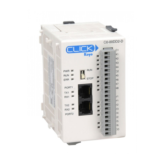
- Page 198 Chapter 3: Installation and Wiring Introduction to the CLICK PLC Mechanical Design CLICK PLC Units All CLICK PLCs are similar in appearance. Please see the diagrams below to familiarize yourself with the PLC features. The main components located on the front of the PLC are a removable 20-pin I/O connector, Run/Stop switch, communications ports and LED status indicators.
- Page 199 Chapter 3: Installation and Wiring Component Locations on Analog PLC Units Analog PLC Mounting Sliding Latch PLC Mode C0-02DD1-D C0-02DD1-D Switch 4 Discrete Inputs LED Status Indicators 4 Discrete Outputs PORT1 PORT1 2 Analog AD1V AD1V Inputs Communication AD1I AD1 I Ports AD2V AD2V...
- Page 200 Chapter 3: Installation and Wiring Component Locations on Ethernet PLC Units Ethernet Standard PLC Mounting Sliding Power Latch Terminal PLC Mode C0-11DD1-D Switch 8 Discrete N.C. Input LED Status Points Indicators PORT1 LINK/ACT ETHER Communication 100MBIT Ports PORT2 6 Discrete Output RS-232 Points...
- Page 201 Chapter 3: Installation and Wiring CLICK I/O Modules Several different types of input and output modules are available for the CLICK PLC system. Please see the diagrams below to familiarize yourself with the I/O module features. Each I/O module is identified as an Input or Output module on its front panel using the color coding scheme listed below.
- Page 202 Chapter 3: Installation and Wiring CLICK Power Supplies All CLICK PLCs require 24VDC input power from either a CLICK power supply or other suitable external power supply. Two models of CLICK power supplies are available to supply power to the PLC and I/O modules. •...
- Page 203 Chapter 3: Installation and Wiring Battery Backup (Standard, Analog and Ethernet PLC Units) All of the CLICK PLC units have a super capacitor to maintain back up data in SRAM. However, the backup period by the super capacitor depends on the CLICK PLC unit type you use.
- Page 204 Chapter 3: Installation and Wiring Mounting Guidelines Environmental Specifications The CLICK family of PLC products should be stored, installed, and used within their range of environmental specifications, such as storage temperature, operating temperature, humidity, environmental air, vibration, shock, and noise immunity. Certain output module circuit types may have derating curves depending on the ambient temperature and the number of outputs ON.
- Page 205 Chapter 3: Installation and Wiring PLC Unit I/O Module Unit Dimensions mm [inches] 3–12 CLICK PLC Hardware User Manual, 5th Edition, Rev. F – C0-USER-M...
- Page 206 Chapter 3: Installation and Wiring PLC Unit System 13.5 34.9 53.5 [0.46] [0.102] [1.37] [2.11] [1.06] [2.95] [3.35] .35] [0.16] " [0.37] Unit Dimensions [0.36] mm [inches] Maximum system: Power Supply + PLC + eight I/O modules. Follow the installation guidelines to allow for proper spacing from other components within an enclosure.
- Page 207 Chapter 3: Installation and Wiring Enclosures Your selection of a proper enclosure is important to ensure safe and proper operation of your CLICK PLC system. Control applications vary and yours may require additional considerations. At a minimum your enclosure should include: •...
- Page 208 CLICK PLC from power surges and EMI/RFI noise. The AutomationDirect Powerline Filter, for use with 120VAC and 240VAC, 1–5 Amps, is an excellent choice (locate at www.automationdirect.com), however, you can use a filter of your choice. The filter units install easily between the AC power source and the PLC.
- Page 209 Chapter 3: Installation and Wiring Installing the CLICK PLC Connecting the Modules Together CLICK PLCs and I/O modules connect together using the Extension Ports that are located on the side panels of the modules. The modules secure together by sliding LOCK/UNLOCK latch tabs located on the top and bottom panels of the modules.
- Page 210 Chapter 3: Installation and Wiring Mounting CLICK PLC System on DIN Rail CLICK PLCs can be secured to a panel by using mounting rails. We recommend rails that conform to DIN EN standard 50 022. They are approximately 35mm high, with a depth of 7mm.
- Page 211 Chapter 3: Installation and Wiring Wiring Guidelines Power Input Wiring to Click Power Supply Connect the AC power source input wiring to the CLICK power supply (the CLICK power supply voltage and current requirements are listed in chapter 2). If you are not using a CLICK power supply, be sure that it meets CLICK PLC requirements.
- Page 212 Chapter 3: Installation and Wiring Fuse Protection Fuse Protection for PLC Input Power External circuit protection is needed to ensure the safety of service personnel and the safe operation of the equipment itself. To meet UL/CUL specifications, the input power must be fused.
- Page 213 Chapter 3: Installation and Wiring Planning the I/O Wiring Routes The following guidelines provide general information on how to wire the I/O connections to CLICK PLCs. For additional information about wiring a particular I/O type refer to the corresponding information in this chapter. 1.
- Page 214 Chapter 3: Installation and Wiring Wiring I/O Modules There are three sizes of I/O module terminal blocks used for field wiring connections (11pt, 13pt & 20pt). They can be removed from the module for wiring convenience. There are no clips or screws retaining the terminal block. Firmly grip the block and pull it away from the PLC or I/O module.
- Page 215 Chapter 3: Installation and Wiring ZIPLink Wiring System Compatibility Matrix for CLICK PLCs Use the following tables to select your ZIPLink components. See our website for more specifications and information on ZIPLinks. CLICK PLC Units ZIPLink Selector ZIPLink PLC Module Terminals Component Module Part No.
- Page 216 Chapter 3: Installation and Wiring ZIPLink Wiring System Compatibility Matrix for CLICK PLCs (continued) CLICK PLC Discrete Input Module ZIPLink Selector I/O Module ZIPLink Input Module Terminals Component Module Part No. Cable Part No. C0-08SIM Not supported by ZIPLink C0-08ND3 C0-08ND3-1 Feedthrough ZL-RTB20...
- Page 217 Chapter 3: Installation and Wiring ZIPLink Wiring System Compatibility Matrix for CLICK PLCs (continued) CLICK PLC Combo I/O Module ZIPLink Selector I/O Module ZIPLink Combo Module # of Terms Component Module Part No. Cable Part No. C0-16CDD1 ZL-C0-CBL20* C0-16CDD2 Feedthrough ZL-RTB20 C0-08CDR ZL-C0-CBL11*...
- Page 218 Chapter 3: Installation and Wiring I/O Wiring Checklist Use the following guidelines when wiring the I/O modules in your system. 1. There is a limit to the size of wire the modules can accept. The table below lists the suggested AWG. When making terminal connections, follow the suggested torque values. Terminal Block AWG and Torque Connector Type (all) Removable Terminal Block...
- Page 219 Chapter 3: Installation and Wiring System Wiring Strategies The CLICK PLC system is very flexible and will work in many different wiring configurations. By studying this section before actual installation, you can find the best wiring strategy for your application. This will help to lower system cost and wiring errors, and avoid safety problems. PLC Isolation Boundaries PLC circuitry is divided into three main regions separated by isolation boundaries, shown in the drawing below.
- Page 220 Chapter 3: Installation and Wiring Powering I/O Circuits In most applications, it will be necessary to power the input devices from one power source, and to power output loads from another source. Loads often require high-energy AC power, while input sensors use low-energy DC. If a machine operator is likely to come in close proximity to input wiring, then for safety reasons, high-energy output circuits would be isolated.
- Page 221 Chapter 3: Installation and Wiring Sinking/Sourcing Concepts Before wiring field devices to the PLC I/O, it’s necessary to have a basic understanding of sinking and sourcing concepts. Use of these terms occurs frequently in input or output circuit discussions. The purpose of this section is to explain the terms. The short definitions are as follows: •...
- Page 222 Chapter 3: Installation and Wiring I/O “Common Terminal” Concepts In order for a PLC I/O circuit to operate, current must enter at one terminal and exit at another. This means at least two terminals are associated with every I/O point. In the figure to the right, the input or output terminal is the main path for the current.
- Page 223 Chapter 3: Installation and Wiring DC Input Wiring Methods CLICK PLCs and I/O modules with DC inputs can be wired as either PLC DC Input sinking or sourcing inputs. The dual diodes (shown in this diagram) Input allow current to flow in either direction. Inputs grouped by a common point must be either all sinking or all sourcing.
- Page 224 Chapter 3: Installation and Wiring PLC DC Sinking Output to Sinking Load Device In the example below, a PLC sinking output point is connected to the sinking input of a field device load. In this case, both the PLC output and field device input are sinking type. Since the circuit must have one sourcing and one sinking device, we add sourcing capability to the PLC output by using a pull-up resistor.
- Page 225 Chapter 3: Installation and Wiring Relay Outputs - Wiring Methods Relay outputs are available for the CLICK PLCs. Relays are best for the following applications: • Loads that require higher currents than the solid-state outputs can deliver • Cost-sensitive applications •...
- Page 226 Oscilloscope 24 VDC Relay Coil (24V/125mA/3W, AutomationDirect part no. 750-2C-24D) In the same circuit, replacing the relay with a larger 24V, 290mA, 7W relay will generate a transient voltage exceeding 800V (not shown). Transient voltages like this can cause many problems, including: •...
- Page 227 Chapter 3: Installation and Wiring PLC’s Integrated Transient Suppressors Although the PLC’s outputs typically have integrated suppressors to protect against transients, they are not capable of handling them all. It is usually necessary to have some additional transient suppression for an inductive load. Here is another example using the same 24V, 125mA, 3W relay used earlier.
- Page 228 784-4C-SKT-1 socket module shown below. If an add-on flyback diode is not available for your inductive load, an easy way to add one is to use an AutomationDirect DN-D10DR-A diode terminal block, a 600VDC power diode mounted in a slim DIN rail housing.
- Page 229 NOT conduct at the supply voltage, while allowing a safe margin. AutomationDirect’s ZL-TSD8-24 transorb module is a good choice for 24VDC circuits. It is a bank of 8 uni-directional 30V TVS diodes. Since they are uni-directional, be sure to observe the polarity during installation.
- Page 230 Chapter 3: Installation and Wiring Analog I/O Configuration Built-in Analog I/O are available in the CLICK models listed below. (Expansion Analog I/O modules are shown on following page.) Analog PLC Units Inputs Outputs C0-02DD1-D C0-02DD2-D C0-02DR-D 2 - Current/ Voltage, 2 - Current/ Voltage, C0-12DD1E-D Selectable...
- Page 231 Chapter 3: Installation and Wiring Some Ethernet Analog PLC units have two built-in analog inputs and two built-in analog outputs. Ethernet Analog Terminals C0-12DD1E-D Terminal Terminal Description Name AD1V Analog voltage input R R R UN AD1I Analog current input STOP S S TOP STOP...
- Page 232 Chapter 3: Installation and Wiring Terminal Block Wiring - Expansion Analog I/O Modules The terminal block wiring will vary depending on which analog I/O module is being used. For example, the C0-04AD-1 module shown here has four analog terminals, CH1 through CH4, which are all current inputs.
- Page 233 Chapter 3: Installation and Wiring Configuration in the CLICK Programming Software All analog I/O points can be configured in the CLICK Programming Software. There is no jumper switch in these modules. Analog PLC units The Analog PLC units cannot detect which terminal is used between the analog voltage and analog current, so you must configure which analog type is used for each analog I/O in the CLICK programming software.
- Page 234 Chapter 3: Installation and Wiring Click the Input tab to configure the analog inputs and/or click the Output tab to configure the analog outputs. The Input tab is shown below, but the Output tab looks very similar. Select analog voltage or current Setup the scaling here You can select the analog voltage or analog current with the radio buttons.
- Page 235 Chapter 3: Installation and Wiring The following is the configuration window for the C0-04AD-1 current input I/O module. In the CLICK PLC, all analog data is stored in the DF memory addresses. Assign DF memory addresses to the Data Register fields. You can also set up the scaling in this configuration window.
- Page 236 Chapter 3: Installation and Wiring Analog I/O Monitoring To monitor the current analog I/O values, you can use the System Monitor window as shown below (Pull-down menu: Monitor > System Monitor). You can switch the displayed values between the physical values and scaled values with the radio buttons below the respective graphic.
- Page 237 Chapter 3: Installation and Wiring High-Speed Input Configuration CLICK CPUs that have built-in digital inputs with High-Speed capability are shown below. The maximum number of available Single Input Counters will depend on the combination of features used. High-Speed High-Speed CPU Type CPU Part Number Input Points Counters (Max.)
- Page 238 Chapter 3: Installation and Wiring Each Input Mode consumes the available number of High-Speed Inputs. The Reset and Enable features can use High-Speed Inputs, Digital Input Modules, or Control Relays (Internal Bits). The transition delay (latency) is longer for Input Modules and Control Relays since these are scan based.
- Page 239 Chapter 3: Installation and Wiring Wiring Examples High Speed Inputs Quadrature with Reset (Z-Pulse): ector) Sinking Encoder (Open Coll Power OUT A OUT B OUT Z Sourcing Encoder Power OUT A OUT B OUT Z 3-Wire Sensors NPN Sensor (Sinking) PNP Sensor (Sourcing) 3–46 CLICK PLC Hardware User Manual, 5th Edition, Rev.
- Page 240 hapter hapter hapter PLC C ommuniCations In This Chapter... Introduction ....................... 4–2 PLC Communication Ports Specifications ..............4–3 LED Status Indicators ....................4–5 3 Steps to Using the CLICK PLC Communications ........... 4–7 Typical Communication Applications ................ 4–8 W-1: Com Port 1 & 2 (RS-232) Wiring ..............4–12 W-2: Com Port 1 (Ethernet) Wiring ................
- Page 241 Chapter 4: PLC Communications Introduction This chapter explains the communications ability of the CLICK PLC system for exchanging data between the PLC unit and other connected serial devices. It covers: • Electrical connections used for communications • Networking routing between the PLC and other devices, •...
- Page 242 Chapter 4: PLC Communications PLC Communication Ports Specifications The CLICK PLC units have two or three built-in communications ports. Basic PLC Standard and Analog PLCs Com Port 1 Com Port 1 Com Port 2 Com Port 2 Com Port 3 Port 1 Com Port 1 Specifications Port 1 Pin Descriptions...
- Page 243 Chapter 4: PLC Communications PLC Communication Ports Specifications (continued) Ethernet Standard and Analog PLCs Ethernet Basic PLC Com Port 1 Com Port 1 Com Port 2 Com Port 2 Com Port 3 Port 1 Com Port 1 Specifications Port 1 Pin Descriptions 8 pin RJ45 Phone Use: Programming and Ethernet Communication 1 TX+...
- Page 244 Chapter 4: PLC Communications LED Status Indicators LED Status Indicators There are LED status indicators located to the left of each communication port to indicate port activity or communications. Port 1 & 2 LED Basic PLC Status Indicators TX1 and TX2 (Green) STOP On The Comm Port is sending data.
- Page 245 Chapter 4: PLC Communications LED Status Indicators (continued) Port 1 & 2 LED Status Indicators LNK/ACT LED (Green) R R R R R R Connected to the network STOP STOP STOP S S S S Ethernet Basic PLC PORT1 PORT1 Blink Communicating LNK/ACT...
- Page 246 Chapter 4: PLC Communications 3 Steps to Using the CLICK PLC Communications We offer an easy 3-step method for using the communication features of the CLICK PLC. Step 1 Step 2 Step 3 Com Port Programming Wiring Setup Pages Pages Pages The following pages show the devices that you may connect to the CLICK PLC Com ports.
- Page 247 Chapter 4: PLC Communications Typical Communication Applications The diagrams on the following four pages illustrate the typical uses for the CLICK PLC’s communication ports. Typical serial communication applications are continued on the next three pages. Port 1 (RS-232) – Modbus RTU Slave Mode Only Port 1 C-more and C-more Another CLICK PLC...
- Page 248 Chapter 4: PLC Communications Port 1 (Ethernet) – Modbus TCP Modbus TCP Client (Master) Devices Port 1 Another CLICK Ethernet PLC Other Devices All Ethernet PLCs Supporting Modbus TCP Client Mode C-more Panel W-2 C-2 Modbus TCP Server (Slave) Devices ViewMarq Display GS1 Drive SR55 Soft Starter...
- Page 249 Chapter 4: PLC Communications Port 2 (RS-232) – Modbus RTU or ASCII Modbus RTU Port 2 Modbus RTU Master Devices Another CLICK PLC All PLCs See Note on previous page about connecting a C-more Micro-Graphic panel to RS-232 Port. ASCII Other Devices C-more and C-more Supporting Modbus RTU...
- Page 250 Chapter 4: PLC Communications Port 3 (RS-485 – Modbus RTU or ASCII) Modbus RTU Port 3 Modbus RTU Master Devices Another CLICK PLC Standard,Analog and Ethernet PLCs ASCII Other Devices C-more and C-more Supporting Modbus RTU Devices that SEND ASCII messages Micro-Graphic Panel Master Mode W-3 C-5...
- Page 251 NOTE: Both Com ports can provide 5VDC; however, the 5VDC power can be used only for the C-more Micro-Graphic panel. AutomationDirect does not guarantee that the CLICK PLC will work correctly when any other device uses 5VDC from these Com ports. Please also remember these Com ports can provide enough power only for one C-more Micro-Graphic panel.
- Page 252 Chapter 4: PLC Communications Case 1: Connect Com Port 1 or 2 to a PC. You can connect Com Port 1 or 2 to a serial com port or USB port on the PC. 1. Connect to a serial port CLICK PLC PC Serial Programming Cable...
- Page 253 Chapter 4: PLC Communications Case 2: Connect Com Port 1 or 2 to another CLICK PLC CLICK PLC CLICK PLC D0-CBL Cable You can use cable D0-CBL. In this configuration, one of the CLICK PLC units needs to be the network master and the other is the network slave.
- Page 254 Chapter 4: PLC Communications Case 4: Connect Com Port 1 or 2 to an RS-232 port on another device You need to cross the RTD and TXD signal lines and connect 0V on both com ports. CLICK Com RS-232 Port on Port 1 or 2 Another Device 1 0V...
- Page 255 Chapter 4: PLC Communications Case 5: Connect Com Port 1 or 2 to an RS-422 or RS485 port on another device(s). You need a RS-232 to RS-422/485 converter in this case. We recommend our FA-ISOCON as the converter. CLICK PLC FA-ISOCON Cable included with FA-ISOCON...
- Page 256 Chapter 4: PLC Communications W-2: Com Port 1 (Ethernet) Wiring Com Port 1 (Ethernet) supports 10/100 Base-T Ethernet with an RJ-45 style connector. Port 1 Pin Descriptions 1 TX+ Transmit Data (+) 8 pin RJ45 Phone Type Jack 2 TX- Transmit Data (-) 3 RX+ Receive data (+)
- Page 257 Chapter 4: PLC Communications Case 2: Connect Com Port 1 to other devices that support the Modbus TCP (client/server) protocol via a switch or hub. NOTE: Com Port 1 can communicate with any number of servers (slaves) using the Receive and/or Send instructions.
- Page 258 Chapter 4: PLC Communications W-3: Com Port 3 Wiring Com Port 3 supports 2-wire RS-485. 3 Pin Terminal Block Port 3 Pin Descriptions 1 + (Plus) Signal A (RS-485) 2 - (Minus) Signal B (RS-485) 3 LG Logic Ground (0 V) Wiring Strategy You need to connect all + signal terminals in the network together.
- Page 259 Chapter 4: PLC Communications C-1: Com Port 1 (RS-232) Setup Com Port 1 has a fixed setup as shown below. This com port works as a Modbus RTU slave only. If you want to connect an external device to this com port, please make sure the external device can be a Modbus RTU master and that the com port setup matches the following setup.
- Page 260 Chapter 4: PLC Communications C-2: Com Port 1 (Ethernet) Setup Wiring Strategy Before you set up this communication port, you must connect a PC loaded with CLICK programming software to the CLICK PLC Port 1 using an Ethernet cable or to the CLICK PLC Port 2 using a D2-DSCBL or EA-MG-PGM-CBL programming cable.
- Page 261 Chapter 4: PLC Communications C-3: Com Port 2 Setup (Modbus RTU) Before you set up the communication ports you must connect the PC with the CLICK programming software to the CLICK PLC Port 1 using a D2-DSCBL or EA-MG-PGM-CBL programming cable. Refer to Chapter 1: Getting Started for step-by-step instructions for this connection.
- Page 262 Chapter 4: PLC Communications C-4: Com Port 2 Setup (ASCII) Before you set up the communication ports you must connect the PC with the CLICK programming software to the CLICK PLC Port 1 using a D2-DSCBL or EA-MG-PGM-CBL programming cable. Refer to Chapter 1: Getting Started for step-by-step instructions for this connection.
- Page 263 Chapter 4: PLC Communications C-5: Com Port 3 Setup (Modbus RTU) Before you set up the communication ports you must connect the PC with the CLICK programming software to the CLICK PLC Port 1 using a D2-DSCBL or EA-MG-PGM-CBL programming cable. Refer to Chapter 1: Getting Started for step-by-step instructions for this connection.
- Page 264 Chapter 4: PLC Communications C-6: Com Port 3 Setup (ASCII) Before you set up the communication ports you must connect the PC with the CLICK programming software to the CLICK PLC Port 1 using a D2-DSCBL or EA-MG-PGM-CBL programming cable. Refer to Chapter 1: Getting Started for step-by-step instructions for this connection.
- Page 265 Chapter 4: PLC Communications P-1: Modbus Slave (Server) Programming Ladder Program To use a CLICK PLC as a Modbus slave (server), you don’t need any special ladder program. Set up the communication port properly and you just need an End instruction in the ladder program to put the PLC in Run mode.
- Page 266 Chapter 4: PLC Communications Modbus Addressing Each of the memory addresses in the CLICK (X1, DS1, etc.) has a unique Modbus address. This means the network master in the Modbus network can access any memory address in the slave CLICK PLC. The best way to check which Modbus address is assigned to a particular CLICK memory address is to use the CLICK programming software.
- Page 267 Chapter 4: PLC Communications Exception Response (Exception Code) When the slave CLICK PLC receives a request from the Modbus master that it cannot respond to, the slave CLICK PLC sends an exception response to the Modbus master. The CLICK PLC supports the following Exception Responses. Exception Response (Exception Code) Code Name...
- Page 268 Chapter 4: PLC Communications P-2: Modbus Master Programming (Modbus RTU) Instructions The CLICK PLC has two instructions to exchange data with external Modbus devices through the com ports; the Receive and Send instructions. • Receive instruction: Read data from an external Modbus device. •...
- Page 269 Chapter 4: PLC Communications When you open the Receive or Send instruction in the Modbus mode, their windows should look like this. For the explanation of each setup parameter, please click the Help button on the bottom right. Click the Help button to get detailed information on this setup window.
- Page 270 Chapter 4: PLC Communications Example Program The ladder program to use these Receive and Send instructions are easy. You just need one NO (Normally Open) contact instruction to check if the com port is ready to receive or send data. When Com Port 2 is ready, the Receive instruction is executed.
- Page 271 Chapter 4: PLC Communications Example Program: Interlocking with Two Slaves (Continued) 4–32 CLICK PLC Hardware User Manual, 6th Edition, Rev. F – C0-USER-M...
- Page 272 Chapter 4: PLC Communications Example Program: Interlocking with Two Slaves (Continued) 4–33 CLICK PLC Hardware User Manual, 6th Edition, Rev. F – C0-USER-M...
- Page 273 Chapter 4: PLC Communications P-3: Modbus Client (Modbus TCP) Programming Instructions The CLICK PLC has two instructions to exchange data with Modbus servers through the Com Port 1; the Receive and Send instructions. • Receive instruction: Read data from external Modbus server. •...
- Page 274 Chapter 4: PLC Communications When you open the Receive or Send instruction in the Modbus mode, their windows should look like this. For the explanation of each setup parameter, please click the Help button on the bottom right. Click the Help button to get detailed information on this setup window.
- Page 275 Chapter 4: PLC Communications Example Program The ladder program to use these Receive and Send instructions are easy. You just need one NO (Normally Open) contact instruction to check if the com port is ready to receive or send data. When Com Port 1 is ready, the Receive instruction is executed.
- Page 276 Chapter 4: PLC Communications Interlocking If you are going to use more than one Receive and/or Send instruction with the same server(slave), you need to be sure only one of the instructions is enabled at any point during the operation. The technique to execute more than one Receive and/or Send instructions in order is called ‘Interlocking’.
- Page 277 Chapter 4: PLC Communications Example Program: Interlocking with a Server (Continued) 4–38 CLICK PLC Hardware User Manual, 6th Edition, Rev. F – C0-USER-M...
- Page 278 Chapter 4: PLC Communications Example Program: Interlocking with a Server (Continued) 4–39 CLICK PLC Hardware User Manual, 6th Edition, Rev. F – C0-USER-M...
- Page 279 Chapter 4: PLC Communications P-4: ASCII Receive Programming Instruction The Receive instruction allows the CLICK PLC to read ASCII message from an external device. To use this instruction, double click Receive in the Instruction List window as shown below. Instruction List Double click Receive in the Instruction List to use it in the ladder program.
- Page 280 Chapter 4: PLC Communications When you open the Receive instruction in the ASCII mode, the window should look like this. For the explanation of each setup parameter, please click the Help button on the bottom right Click the Help button to get the detailed information of this setup window.
- Page 281 Chapter 4: PLC Communications Example 2: Retrieve numerical data from the received ASCII message. Barcode Reader Copied System Data Register SD50 stores the number of received TXT1 characters for Port 2. SD50 TXT2 TXT3 When numerical data is included in the received ASCII message, you may want to retrieve the numerical data and copy into a data register.
- Page 282 Chapter 4: PLC Communications P-5: ASCII Send Programming Instruction The Send instruction allows the CLICK PLC to send ASCII messages to an external device. To use this instruction, double click Send in the Instruction List window as shown below. Instruction List Double click Send in the Instruction List to use it in the ladder program.
- Page 283 Chapter 4: PLC Communications When you open the Send instruction in the ASCII mode, the window should look like this. For the explanation of each setup parameter, please click the Help button on the bottom right. Click the Help button to get detailed information on this setup window.
- Page 284 hapter hapter hapter aintenance In This Chapter... PLC Maintenance ....................... 5–2...
- Page 285 Chapter 5: Maintenance PLC Maintenance Although the CLICK PLC requires very little maintenance, setting up a routine maintenance schedule will ensure the longevity of the PLC in your application. We suggest checking the following items as part of a quarterly or bi-annual preventative maintenance schedule. Check LED Indicators Check the PWR and ERR LED indicators on the PLC and I/O modules.
- Page 286 Chapter 5: Maintenance Check Physical Condition Check the PLC and modules for distorted, warped, or discolored cases and burnt odors that could indicate overheated components. Check to ensure that none of the PLC and module cooling vents are clogged or blocked by dust or debris.
- Page 287 hapter hapter hapter roubleshooTing In This Chapter... Troubleshooting Direction ..................6–2 PLC unit Troubleshooting ..................6–3 Power Supply Troubleshooting ................. 6–5 I/O Module Troubleshooting ..................6–6 Troubleshooting Electrical Noise Problems ............6–10 Error Codes ......................6–11...
- Page 288 Chapter 6: Troubleshooting Troubleshooting Direction Use this section to figure out where to start when troubleshooting CLICK PLC problems. Problem with Problem with I/O modules? PLC unit? Go to Go to Problem with Page 6-6 Page 6-3 power supply? Go to Page 6-5 6–2 CLICK PLC Hardware User Manual, 6th Edition, Rev.
- Page 289 Chapter 6: Troubleshooting PLC unit Troubleshooting PLC unit issues are grouped according to their function. Use the illustration below to find the appropriate document page numbers for issues with different PLC unit functions. Problem with C0-00DD1-D toggle switch? Go to Page 6-3 Problem with LED indicators?
- Page 290 Chapter 6: Troubleshooting LED Indicators The CLICK PLC performs many pre-defined diagnostic routines with every PLC scan, using onboard diagnostics that can detect various errors or failures in the PLC. LEDs on the face of the PLC will indicate for specific errors. The 3 LEDs located next to the RUN/STOP switch power, (PWR, RUN and ERR) indicate the status of the PLC unit.
- Page 291 Chapter 6: Troubleshooting Power Supply Troubleshooting When the PWR LED is ON, the CLICK PLC is receiving enough power for operation. Verify the power input voltage at the bottom connector on the PLC unit; the input voltage should be 20–28 VDC. The input voltage measures less than 20VDC Remove the bottom connector from the CLICK PLC unit and measure the voltage again.
- Page 292 Chapter 6: Troubleshooting I/O Module Troubleshooting First, check the status of the PWR LED indicators on the I/O modules. If the PWR LED on the PLC unit is on, but there are I/O modules which have PWR LEDs that are off, check the connections between the modules.
- Page 293 Chapter 6: Troubleshooting Output Module Troubleshooting The output modules (including the PLC built-in outputs) can have the following symptoms: Symptom Necessary Action Check the external power input voltage on the terminal block. Check whether the terminal block is attached correctly. If it is a DC sinking, relay, or AC output, check the voltage between the output and the The module LED indicator is ON, but...
- Page 294 Chapter 6: Troubleshooting How to Check the I/O Status You can use CLICK programming software Data View window to check the I/O status in the PLC unit. WARNING: Only authorized personnel fully familiar with all aspects of the application should make changes to the program.
- Page 295 Chapter 6: Troubleshooting Replacement of I/O modules WARNING: The CLICK PLC does not have hot swap capability. Do not disconnect or replace any I/O modules without first shutting off power to the PLC PLC unit. Before replacing an I/O module, please consider the cause of the module problem. If you suspect that another device may have caused the failure in the module, that device may also cause the same failure in the replacement module.
- Page 296 Chapter 6: Troubleshooting Troubleshooting Electrical Noise Problems Electrical Noise Problems Noise is one of the most difficult problems to diagnose. Electrical noise can enter a system in many different ways and can fall into one of two categories, conducted noise or radiated noise. It may be difficult to determine how the noise is entering the system, but the corrective actions are similar for both types of noise problems.
- Page 297 Chapter 6: Troubleshooting Error Codes When there is an Error or Warning, the error code is stored in the System Data register SD1. When an Error occurs during the operation, the CLICK PLC system goes to the STOP mode immediately and the ERR LED on the PLC unit turns on. On the other hand, when a Warning occurs during the operation, the CLICK PLC system stays in RUN mode and the ERR LED on the PLC unit starts blinking.
- Page 298 Chapter 6: Troubleshooting Error Codes (continued) PLC Error Codes Error Status Error Category Causes Solutions Code Flag* Name Power off the CLICK PLC and check the connection of the I/O modules. Then power on the CLICK PLC again. If the At least one I/O module was problem remains, connect the CLICK software to the PLC removed from the CLICK PLC...
- Page 299 Chapter 6: Troubleshooting Error Codes (continued) PLC Error Codes Error Status Error Category Causes Solutions Code Flag* Name IO1 Module The analog I/O module in I/O1 Power cycle the CLICK PLC. If the same error occurs X101 Error position is not functioning. again, replace the analog I/O module.
- Page 300 Chapter 6: Troubleshooting Error Codes (continued) PLC Error Codes Error Status Error Category Causes Solutions Code Flag* Name CH3 on the analog I/O module in IO2 CH3 Check the wiring for CH3. X209 Warning I/O2 position senses burnout or Replace the sensor if it is broken. Burnout open circuit.
- Page 301 Chapter 6: Troubleshooting Error Codes (continued) PLC Error Codes Error Status Error Category Causes Solutions Code Flag* Name CH4 on the analog I/O module in IO5 CH4 Check the wiring for CH4. X512 Warning I/O5 position senses burnout or Burnout Replace the sensor if it is broken.
Need help?
Do you have a question about the CLICK Series and is the answer not in the manual?
Questions and answers