Table of Contents
Advertisement
Quick Links
GLOBAL GEARED MOTOR
OPERATION MANUAL
GUS
SERIES
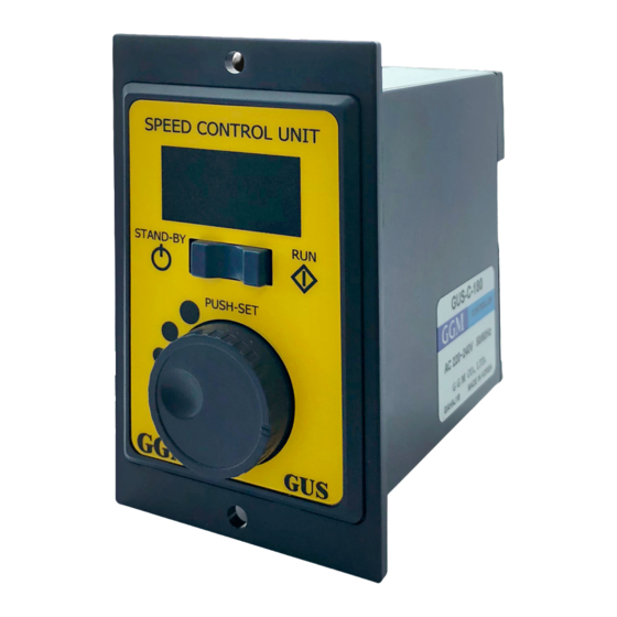
SPEED CONTROL UNIT
■ Headquarters / 1st Factory : 22, Gyeongin-ro 3beon-gil, Bucheon-si, Gyeonggi-do, Republic of Korea
Tel:+82-32-664-7790 Fax:+82-32-611-7791
■ Attached research institute / No. 2 factory : 180, Oksan-ro, Bucheon-si, Gyeonggi-do, Republic of Korea
Tel:+82-32-684-7791
Fax:+82-32-683-5059
www.ggm.co.kr
SEMI DIGITAL
Advertisement
Table of Contents

Related Manuals for GGM GUS Series


Summary of Contents for GGM GUS Series
- Page 1 GLOBAL GEARED MOTOR OPERATION MANUAL SERIES SEMI DIGITAL SPEED CONTROL UNIT ■ Headquarters / 1st Factory : 22, Gyeongin-ro 3beon-gil, Bucheon-si, Gyeonggi-do, Republic of Korea Tel:+82-32-664-7790 Fax:+82-32-611-7791 ■ Attached research institute / No. 2 factory : 180, Oksan-ro, Bucheon-si, Gyeonggi-do, Republic of Korea...
-
Page 2: Safety Precautions
Thank you for purchasing a GGM product. To ensure that you areusing this product correctly, make sure to first read this operation manual thoroughly and familiarize yourself with allknowledge, safety information and precautions related tothe product. After you have read this operation manual, keep it at hand for reference whenneeded. - Page 3 Ignoring this warning and handling the Warning product incorrectly may cause injury or property damage. • Do not forcethe motor or speed controller to operate outside oftheirspecifications. Doing so may cause an electric shock, injury or product damage. • Do not operate the product with wet hands. Doing so may cause an electric shock. •...
-
Page 4: Specifications
2. Confirmation when the product is handed over - Confirm that the delivered product is the product you ordered. - If a different product is installed, it will create the risk of injury or fire. - Contact a nearby retail store if you were delivered an insufficient number of products or if a damaged product wasdelivered. - Page 5 4. CONTROLLER CODING SYSTEM C : Single Phase 06 : 6W AC220V 50/60Hz 15 : 15W AC230V 50/60Hz 25 : 25W Unit Semi AC240V 50/60Hz 40 : 40W Co.,LTD. Type Digital 60 : 60W Type U : Single Phase 90 : 90W AC110V 50/60Hz 120 : 120W 180 : 180W...
- Page 6 6. Characteristics of the product ① Indicates the current rotation speed (r/min). ② The motor speed can be controlled simply by connecting the motor and the control unit with the exclusive connector and connecting the AC terminal to the power source. ③...
-
Page 7: Names And Functions Of Each Part
8. Names and functions of each part External operation switch [ Thisis used for starting or stopping external operation. / When it is set Display unit to ON, the motor operates. [ Displays the rotation speed when it is set to OFF, the motor and parameters ] stops. - Page 8 ▶ External operation wiring ▶ Two-way operation wiring Motor connector Motor connector 1) Connect the motor connector. 1) Connect the motor connector. 2) Install the power supply switch (SW1) 2) Connect the ②COM and ③CW terminals. (CW operation) and the forward and reserve rotation exchange switch (SW2) and change the Refer to the CCW operation and two-way rotation direction.
- Page 9 9-2 Operation sequence After wiring, operate the product as follows. ① AC power supplied The indication turns on. (Rotation speed) ② Control of operation switch (operation) When you movethe operation switch to RUN, the motor will rotate. ③ Setting the rotation speed When you turn the dial, the rotation speed will change.
-
Page 10: Parameter Setting Sequence
9-4 Parameter setting sequence ① Supply AC power The indication turns on. (Rotation speed) ② Entering the parameter mode Press and hold the dial (PUSH-SET) for 3 seconds to enter the parameter mode. ③ Selection of a parameter Turn the dial and select the desired parameter(4 parameters) Modes can be selectedin the order of RATE(reduction gear ratio) →... -
Page 11: Troubleshooting
10. Attachment method ■ Panel process drawing 1. Drill a hole in the attachment panel as shown in the figure below. Assemble the controller body and the front cover and fix them using an M4 screw and nut. 2. Use an attachment panel with a thickness of 2mm or less. Attachment Panel 2-M4 or 2-Φ4.5 2-M4 screw... - Page 12 ※ Contact your vendor or our second factory if you haveany questions about product or requirepost-sales service. Leader of geared motor GGM CO.,LTD. http://www.ggm.co.kr Headquarters / 1st Factory Attached research institute / No. 2 factory 22, Gyeongin-ro 3beon-gil, Bucheon-si, 180, Oksan-ro, Bucheon-si, Gyeonggi-do,...
Need help?
Do you have a question about the GUS Series and is the answer not in the manual?
Questions and answers