YOKOGAWA XL100 Series User Manual
Portable data station, portable data logger
Hide thumbs
Also See for XL100 Series:
- User manual (51 pages) ,
- User manual (134 pages) ,
- User manual (137 pages)

Related Manuals for YOKOGAWA XL100 Series


Summary of Contents for YOKOGAWA XL100 Series
- Page 1 User’s XL100 Manual (XL121/XL122/XL124) Portable Data Station (Datum-Y) (XL111/XL112/XL114) Portable Data Logger (Datum-Y) IM XL120E IM XL120E 1st Edition: April 2007 (MC)
- Page 2 The company and product names referred to in this document are either trademarks or registered trademarks of their respective holders. Revision Information First Edition: April, 2007 1st Edition: April 2007 (MC) All Rights Reserved, Copyright © 2005, Yokogawa Meters & Instruments Corporation IM XL120E...
-
Page 3: Checking The Contents Of The Package
Checking the Contents of the Package After opening the package, be sure to check the product as instructed below before use. Should the product you have received be the wrong model, lack any items, or show any problems in its appearance, contact the vendor from whom you purchased the product. Instrument Main Unit Check the model and suffix code printed on the nameplate on the rear panel to ensure that the XL100 is exactly as specified in your purchase order. - Page 4 Checking the Contents of the Package (Example: 95052) Note: Accessory items 1 to 3 come installed in the XL100. Accessories and Spare Parts (Optional) The products listed below are available as optional accessories and spare parts. For technical and ordering inquiries concerning accessories and spare parts, contact the vendor from whom you purchased the product.
-
Page 5: Safety Precautions
If you use the instrument in any way other than as instructed in this manual, the instrument’s protective measures may be impaired. Yokogawa Meters & Instruments Corporation is by no means liable for any damage resulting from use of the instrument in contradiction to these cautionary notes. - Page 6 • Do Not Damage the Power Cord • To prevent electric shock or fire, be sure to use the power cord supplied by YOKOGAWA. • Do not place any load on the power cord or allow the power cord to come into contact with any heat source.
-
Page 7: Language Setting At Startup
Language Setting at Startup Language Setting at Startup When you start up the XL100 for the first time (the first time you turn on the XL100 after purchase), you must set the language that you are going to use. Follow the procedure below to set the language. -
Page 8: Table Of Contents
Contents Checking the Contents of the Package ..................2 Safety Precautions ......................... 4 Language Setting at Startup ......................6 Chapter 1 Explanation of Functions Overview of the XL100 ..................... 1-1 Functions of the Input Section ..................1-2 Display Function ......................1-5 Alarm Function ......................... - Page 9 Contents Chapter 6 Setting Alarms Setting the Alarm on Analog Input Channels ..............6-1 Setting the Alarm on Pulse Input Channels ..............6-3 Setting the Alarm on Logic Input Channels ..............6-5 Setting Alarms on Calculation and Communication Channels (Communication channels are supported only on the XL121, XL122, and XL124) ............
- Page 10 Contents Chapter 11 Other Functions 11.1 Setting the Print Output and Executing the Print Operation (Supported only on the XL121, XL122, and XL124) ......................11-1 11.2 Setting the Beep Sound ....................11-4 11.3 Set the ID Number ......................11-5 11.4 Setting the Language .....................
-
Page 11: Chapter 1 Explanation Of Functions
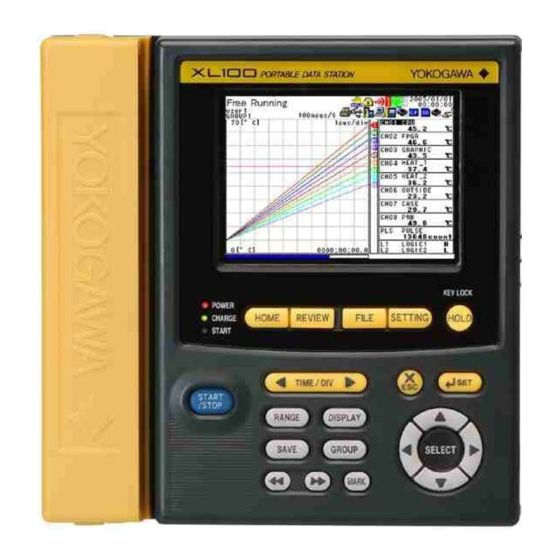
Chapter 1 Explanation of Functions Overview of the XL100 The XL100 is a handheld data logger that (1) periodically samples DC voltage or analog input such as thermocouples and RTDs, (2) acquires the sampled measured data in the internal memory, and (3) displays the measured data on a LCD in the form of waveforms, digital display, and bar graphs. -
Page 12: Functions Of The Input Section
Functions of the Input Section Number of Measurement Channels and Sampling Interval There are two types of analog input terminals, 8 channels or 16 channels. Terminal block unit (8 ch): 95052 Terminal block unit (16 ch): 95053 M3 screws terminal block unit (16 ch): 95055 The sampling interval (scan interval and data storage interval) varies depending on the number of input channels as shown in the table below. - Page 13 1.2 Functions of the Input Section • Thermocouple or RTD Select from the thermocouple types or RTD types listed in the following table. Input Type Type Measurable Range Thermocouple 0 to 1768 °C 0 to 1768 °C 600 to 1800 °C –200.0 to 1372.0 °C –200.0 to 1000.0 °C –200.0 to 1200.0 °C...
- Page 14 1.2 Functions of the Input Section Reference Junction Compensation (RJC) When measuring temperature with a thermocouple, the XL100 uses its internal reference junction compensation function. Average Function The average function performs moving average defined by the equation below on the measured data to suppress the effects of noise riding on the signal.
-
Page 15: Display Function
Display Function Display The XL100 is equipped with a 3.5-inch color LCD monitor (320 dots horizontal × 240 dots vertical). The screen consists of the status display section and the data display section. • Status Display Section Displays the screen name, date/time, internal memory and external storage media usage, communication condition, operation mode, alarm occurrence, key lock, user name (key login function), calculation, power condition, etc. - Page 16 1.3 Display Function The displays shown below are available. For a description of the displayed contents, see section 2.3, “Data Display” and 2.4, “Setup Display.” • Waveform & Digital Display • Digital Display • Bar Graph Display • Review display •...
- Page 17 1.3 Display Function • Log (Communication Command) Display • Log (FTP Client) Display • Log (Web Operation) Display • Log (E-mail Transmission) Display • File Operation Screen • Setup Display Index IM XL120E...
- Page 18 1.3 Display Function Group Display On the waveform display, digital display, and bar graph display, the data of up to eight channels can be shown on a single screen. The eight channels can consist of a combination of analog input channels (hereafter referred to as “measurement channels”), calculation channels (see section 1.6, “Calculation Function), and communication channels (see section 1.8, “Communication Function).
-
Page 19: Alarm Function
Alarm Function This function generates an alarm when the measured/calculated value meets a certain condition. When an alarm occurs, information notifying the alarm occurrence is displayed on the screen. In addition, an alarm signal can be delivered from the output terminal (digital I/O connector) on the rear panel of the XL100. - Page 20 1.4 Alarm Function Delay Alarm An alarm occurs when the measured/calculated value remains above (or below) the alarm value for a specified time period (delay period). In the figure below, the measured value exceeds the alarm value during period T1, but no alarm is generated, because the condition does not last longer than the specified delay period T.
- Page 21 Data Save/Load Function and File Operation Function Measured data, calculated data, setup data, and so forth can be saved to the XL100 internal memory or an external storage medium (CF card or SD card) that is inserted in the XL100 Save the data Types of Data That Can Be Saved Type...
- Page 22 1.5 Data Save/Load Function and File Operation Function Triggers In addition to using the keys to start or stop the logging (data save operation), a trigger for starting (or stopping) the save operation of the logging data (measured/calculated data) can be configured for automatic operation. The trigger can be selected from the list below and configured.
- Page 23 Calculation Function Arithmetic Calculation Arithmetic calculation on variables such as measured data and calculated data (the result of the calculation) and constants that you can arbitrarily define can be executed. The result of the calculation can be displayed on (save to) any of the 32 channels provided specifically for calculation (hereafter referred to as calculation channels).
- Page 24 Setup Function You can specify various settings shown below using keys in Setting Mode. Setup TOP Data Save System Input Alarm Calculation Hardware Display Communication settings settings settings settings settings settings settings settings INPUT > ANALOG INPUT Set the tag, input type (mode), input range, span upper and lower values, color, line width, average, and scaling for the analog input.
-
Page 25: Data Save/Load Function And File Operation Function
1.7 Setup Function DISPLAY Specify general display settings (background color, grid, and bar graph base position), group settings (group name and channel assignments), alarm line settings (alarm line display ON/OFF, color, and line width), and LCD setting (LCD backlight auto OFF). DATA SAVE Set the sampling interval, data save destination, data type, file name, printer output ON/ OFF, and trigger. -
Page 26: Setup Function
1.7 Setup Function CALCULATION Specify calculation settings (assignment of the calculation items 1 and 2, tag, calculation method, constant exponent, and constant coefficient, decimal place, span upper and lower values, unit, color, and line width) and statistical calculation settings (ON/OFF of each statistical calculation item). -
Page 27: Communication Function (Supported Only On The Xl121, Xl122, And Xl124)
Communication Function (Supported only on the XL121, XL122, and XL124) The XL100 comes standard with an Ethernet interface, USB interface, and serial interface (RS-232 and RS-485). XL100 Communication Functions Maintenance/ Setting/Measurement server Test server server server MODBUS MODBUS E-mail client FTP client Application Slave... - Page 28 1.8 Communication Function In addition, e-mail can be sent automatically from the XL100 when an alarm occurs. E-mail reception Ethernet E-mail transmission E-mail reception The USB interface or serial interface can be used to change the XL100 settings from a PC or retrieve data into the PC through command communication.
-
Page 29: Other Main Functions
Other Main Functions Setting the Displayed Language The displayed language can be switched between English and Japanese. If English is specified, you can set the temperature unit to °C or °F. Printer Output (Supported only on the XL121, XL122, and XL124) Measured data and screen image data can be printed on a dedicated printer (97010) sold separately by using the RS-232 interface. -
Page 30: Chapter 2 Part Names And Functions
Chapter 2 Part Names and Functions Front Panel and Terminal Block Unit Front Panel Display Terminal block unit Terminal cover Displays measured data, operation A terminal block unit for connecting (Cannot be removed status, setting menu, settings, etc. analog input signal wires. Can be from the terminal The displayed contents vary removed from the XL100. - Page 31 2.1 Front Panel and Terminal Block Unit Keys HOME REVIEW FILE SETTING HOLD TIME / DIV START / STOP RANGE DISPLAY SAVE GROUP SELECT MARK 1. HOME Key Press this key to enable Free Running Mode for measuring instantaneous values. 2.
-
Page 32: Side Panel And Rear Panel
Side Panel and Rear Panel Side Panel USB port for USB memory For a description, see section 3.9. Ethernet port* For a description, see section 3.8. USB port for connecting a PC* For a description, CF card slot see section 3.8. For a description, see section 4.7. -
Page 33: Data Display
Data Display Status display section Data display section Status Display Section 1. Operation Mode Displays the mode name: Free Running, Logging, Logging & Review, Setup, or File Operation. For Logging and Logging & Review modes, the text background turns light blue to indicate that logging is in progress. 2. - Page 34 2.3 Data Display 8. Various Icons The following icons are used to display the operation status, interface usage status, etc. An icon shown when the data save destination is set to internal memory. The icon blinks when there is access to the internal memory. The icon is gray when the data save destination is not set to internal memory.
- Page 35 2.3 Data Display An icon shown when the data save destination is set to SD card and the memory full operation is set to REPEAT. The icon blinks when there is access to the SD card. (Supported only on the XL121, XL122, and XL124.) An icon shown when the data save destination is set to SD card and the memory full operation is set to DELETE.
- Page 36 2.3 Data Display Data Display Section Waveform & Digital Display 1. Waveform Waveforms of measured data, calculated data, and communication input data. The display position of logic input waveforms is fixed to the bottom of the display as shown below. 2.
- Page 37 2.3 Data Display 11. Unit Displays preset characters such as °C or an arbitrary specified characters (up to 6 characters). 12. Channel No./Tag Displays the channel number and the specified tag (up to 8 characters). The active channel is shown highlighted in reverse video. Waveform Display 1.
- Page 38 2.3 Data Display Digital Display 1. Digital Display Displays the current values of the measured data, calculated data, and communication input data using numeric values. When an alarm is occurring, the value is shown in red in reverse video. 2. Channel No. Displays the channel number in the specified color.
- Page 39 2.3 Data Display Bar Graph Display 1. Bar Displays the current values of the measured data, calculated data, and communication input data using bars. The reference position of the bar can be set to normal (left edge of the scale) or center. The color of the bars are the same as the waveform colors.
- Page 40 2.3 Data Display Review Display 1. Waveform Waveforms of measured data, calculated data, and communication input data. 2. Time Scale The specified time scale (time per grid (division)) is displayed in the format “xxyyy/ div” (where xx is the value and yyy is sec, min, or h). 3.
- Page 41 2.3 Data Display 13. Display Position and Marker Position Shows the displayed range with respect to the entire data using a blue bar. Marker positions are also displayed. The entire saved data Displayed range Marker ALM Marker A Marker B 14.
- Page 42 2.3 Data Display Logging & Review Display 1. Past Waveforms Waveforms of the past measured data, calculated data, and communication input data. 2. Current Waveforms Waveforms of the current measured data, calculated data, and communication input data. 3. Time Scale The specified time scale (time per grid (division)) is displayed in the format “xxyyy/ div”...
- Page 43 2.3 Data Display 14. Display Position and Marker Position Shows the displayed range with respect to the entire data using a blue bar. Marker positions are also displayed. The entire saved data Displayed range Marker ALM Marker A Marker B 15.
- Page 44 2.3 Data Display Alarm Summary Display 1. Selected Alarm No./Total Number of Alarms Displays the number of the alarm selected with the arrow keys and the total number of alarms (up to 120*). * If the total number of logs exceeds 120, the log is deleted from the oldest one. 2.
- Page 45 2.3 Data Display Log (Key Login/Logout) Display 1. Last Line Log No./Total Number of Logs Displays the log No. shown at the last line of the display and the total number of logs (up to 50*). * If the total number of logs exceeds 50, the log is deleted from the oldest one. 2.
- Page 46 2.3 Data Display Log (FTP Client) Display 1. Last Line Log No./Total Number of Logs Displays the log No. shown at the last line of the display and the total number of logs (up to 50*). * If the total number of logs exceeds 50, the log is deleted from the oldest one. 2.
- Page 47 2.3 Data Display Log (E-mail Transmission) Display 1. Last Line Log No./Total Number of Logs Displays the log No. shown at the last line of the display and the total number of logs (up to 50*). * If the total number of logs exceeds 50, the log is deleted from the oldest one. 2.
-
Page 48: Setup Display
Setup Display Status display section Menu/Setting display section A brief description of the selected item Status Display Section 1. Setup Item 1 Displays the item that is one level higher than the current item that you are setting. 2. Setup Item 2 Displays the current item that you are setting. - Page 49 2.4 Setup Display Menu/Setting Display Section The display content changes by selecting the desired item using the arrow/ SELECT key as shown below. SELECT SELECT SELECT 2-20 IM XL120E...
- Page 50 2.4 Setup Display A List of Setup Displays Setup TOP Input Analog Input Pulse Input Logic Input Mode Range Span Lower Display Span Upper Color General Average Group Alarm Line Scaling Data Save Sampling Interval Save Media Data Type Save Mode File Division File Name Memory Full...
- Page 51 Chapter 3 Handling Precautions and Wiring Handling Precautions If you are a first-time user, make sure to thoroughly read “Safety Precautions” given on pages 4 and 5. • Do not place any objects on the instrument. Do not place other devices or a container filled with water on the instrument, otherwise a breakdown may occur.
- Page 52 Operating Environment Installation Location Indoors. Do not install the XL100 in a location that is: • outdoors, • exposed to direct sunlight or close to a heat source, • exposed to a relatively large amount of lampblack, steam, dust, corrosive gas, •...
- Page 53 3.2 Operating Environment Pollution Degree Pollution Degree applies to the degree of adhesion of a solid, liquid, or gas which deteriorates withstand voltage or surface resistivity. The pollution degree of the XL100 in the operating environment is 2. Pollution Degree 2 applies to normal indoor atmospheres.
-
Page 54: Wiring The Input Signal Cable
Wiring the Input Signal Cable Analog Input CAUTION • If a strong tension is applied to the cord wired to the terminal block, the terminals and/or the cord can be damaged. Allow extra wire for the input signal cable so that direct tension is not applied to the input terminals of the terminal block. - Page 55 3.3 Wiring the Input Signal Cable Terminal Block Unit The following two types of terminal block units are available. 16 ch (95053): Clamp screw 8 ch (95052): Clamp screw 16 ch (95055): M3 screw Wiring Procedure <Clamp screw> 1. Open the terminal cover of the terminal block unit. 2.
- Page 56 3.3 Wiring the Input Signal Cable Wiring Diagram DC voltage input TC input DC voltage input – – Extension leadwire RTD input DC current input DC current input – – Lead wire resistance per wire of 10 Ω or less. Shunt resistor Make the resistance of the three wires equal.
- Page 57 Wiring the Pulse Input, Logic Input, and Signal Cables CAUTION • Do not apply an input exceeding the following values. Pulse input or logic input: 10 V. Alarm output: 40 V • If a strong tension is applied to the cable wired to the terminal, the terminals and/or the cable can be damaged.
-
Page 58: Wiring The External I/O Signal Cables
Wiring the External I/O Signal Cables CAUTION • Applying voltage outside the allowable input voltage (–0.5 to 10 V) to the signal input terminal may damage the internal circuitry. • If the trigger mode is set to Continuous, apply the trigger input signal at an interval greater than or equal to 30 s. - Page 59 3.5 Wiring the External I/O Signal Cables Trigger Input Signal Specifications Apply the signal using 0 V (low) and 5 V (high). • Input level: Low 0.0 to 0.8 V. High 2.0 to 5.0 V • Allowable voltage: –0.5 to 10 V Signal Wires That Can Be Used •...
-
Page 60: Connecting The Power Supply
Use the AC adapter supplied with the XL100 when connecting the XL100 to a power supply. WARNING • Use only the power cord supplied by YOKOGAWA Meters & Instruments for the XL100. • Check that the power source voltage matches the supply voltage rating (100 to 240 VAC), and then connect the power cord. -
Page 61: Handling Of The Lithium Ion Battery (Sold Separately)
Handling of the Lithium Ion Battery (Sold Separately) Loading the Lithium Ion Battery If you purchased a lithium ion battery (94009), follow the steps below to load it into the XL100. 1. Loosen the battery cover attachment screw with a flat-blade screwdriver and remove the battery cover. 2. -
Page 62: Connecting Communication Cables (Supported Only On The Xl121, Xl122, And Xl124)
Connecting Communication Cables (Supported only on the XL121, XL122, and XL124) Connecting to the Ethernet Interface LAN Port Position and LAN Cable Connection Connect a LAN cable to the LAN port on the rear panel of the XL100 as shown below. LAN port AL AR M LAN cable... - Page 63 3.8 Connecting Communication Cables Connecting the Serial Interface RS-232 • Position of the RS-232 Connector RS-232 connector DC INPUT 20W MAX LOGIC/PULSE POWER RS485 RS232 ALARM TRIGGER • Connector type: Mini DIN, 8 pins • Connector pin arrangement Pin Number Signal Name Meaning CS (Clear to Send)
- Page 64 3.8 Connecting Communication Cables • Connecting to another measuring instrument (Modbus communication) The figure below shows an example when connecting the XL100 to our CW120/ CW121 Clamp-on Power Meter. XL100 CW120/CW121 HOLD HOME REVIEW FILE SETTING TIME / DEV START / STOP RANGE DISPLAY...
- Page 65 3.8 Connecting Communication Cables • Connecting to a measuring instrument (Modbus communication) Another measuring Another measuring XL100 instrument instrument Connect a 120 Ω Connect a 120 Ω terminator terminator Pair Communication cable Communication cable Up to 31 stations • Position of the USB port for connecting to a PC USB port for connecting a PC DC INPUT 20W MAX...
-
Page 66: Connecting The Usb Memory
Connecting the USB Memory CAUTION • Use USB memories that Yokogawa Meters & Instruments have checked for compatibility. • Before removing the USB memory, check that it is not being accessed. If you remove the USB memory while it is being accessed, files stored on the USB memory or the XL100 may be damaged. -
Page 67: Chapter 4 Basic Operation
Chapter 4 Basic Operation Turning ON/OFF the Power Switch Items to Be Checked before Turning ON the Power • Check that the instrument is installed properly (see section 3.2, “Operating Environment”). • Check that the power cord and AC adapter are connected properly (see section 3.6, “Connecting the Power Supply”). - Page 68 4.1 Turning ON/OFF the Power Switch • If the Key Login Function Is Turned ON When you press a key after the Free Running Mode display appears, a window for entering a user name and password opens. If you enter the user name and password correctly according to the explanation given in section 11.7, “Key Login/Logout Setup and Operation.”...
- Page 69 4.1 Turning ON/OFF the Power Switch • If you change the terminal block (if the number of channels changes), the settings are initialized. The previous setting data (setting data before the terminal block is changed) is automatically stored to the setting memory to a file named “year month date hour minute second Cxx.SET”...
-
Page 70: Basic Key Operations
Basic Key Operations Operation Mode and Key Operations There are six modes in the XL100 as shown below. You can switch the operation mode using the five keys, HOME, REVIEW, FILE, SETTING, and START/STOP, at the top section. HOME REVIEW FILE SETTING Free Running Mode... - Page 71 4.2 Basic Key Operations Key Operations in Free Running Mode • When Displaying the Waveform, Numeric Values, or Bar Graph HOME REVIEW FILE SETTING HOLD TIME / DIV START / STOP RANGE DISPLAY SAVE GROUP SELECT MARK REVIEW Key Switches to Review Mode in which saved data can be analyzed. FILE Key Switches to File Operation Mode in which saved measured data can be loaded, file can be renamed, measured data can be copied, and setup data can be saved or...
- Page 72 4.2 Basic Key Operations • When Displaying the Alarm Summary/Log HOLD HOME REVIEW FILE SETTING TIME / DIV START / STOP RANGE DISPLAY SAVE GROUP SELECT MARK 1. REVIEW Key Switches to Review Mode in which saved data can be analyzed. 2.
- Page 73 4.2 Basic Key Operations Key Operations in Logging Mode • When Displaying the Waveform, Numeric Values, or Bar Graph HOME REVIEW FILE SETTING HOLD TIME / DIV START / STOP RANGE DISPLAY SAVE GROUP SELECT MARK 1. REVIEW Key Switches to Logging & Review Mode in which the current and past data are shown on split screens.
- Page 74 4.2 Basic Key Operations • When Displaying the Alarm Summary/Log HOME REVIEW FILE SETTING HOLD TIME / DIV START / STOP RANGE DISPLAY SAVE GROUP SELECT MARK 1. REVIEW Key Switches to Logging & Review Mode in which the current and past data are shown on split screens.
- Page 75 4.2 Basic Key Operations Key Operations in Review Mode HOME REVIEW FILE SETTING HOLD TIME / DIV START / STOP RANGE DISPLAY SAVE GROUP SELECT MARK HOME Key Switches to Free Running Mode in which instantaneous values are measured. FILE Key Switches to File Operation Mode in which saved measured data can be loaded, file can be renamed, measured data can be copied, and setup data can be saved or loaded.
- Page 76 4.2 Basic Key Operations 13. SELECT Key Displays the review file load window when the SELECT FILE box is selected. 14. SET key Pressing the SET key calculates statistics between cursors A and B when displaying statistics. (The statistics between logging start and logging stop are displayed immediately after the screen is switched.) 4-10 IM XL120E...
- Page 77 4.2 Basic Key Operations Key Operations in Logging & Review Mode HOME REVIEW FILE SETTING HOLD TIME / DIV START / STOP RANGE DISPLAY SAVE GROUP SELECT MARK REVIEW Key Switches to Logging Mode. HOLD Key Hold the key down to enable key lock. Hold the key down again to disable key lock. TIME/DIV Key Press this key to switch the time scale (the time per grid).
- Page 78 4.2 Basic Key Operations Key Operations in the Setting Mode HOME REVIEW FILE SETTING HOLD TIME / DIV START / STOP RANGE DISPLAY SAVE GROUP SELECT MARK 1. HOME Key Switches to Free Running Mode in which instantaneous values are measured. 2.
- Page 79 4.2 Basic Key Operations Key Operations in File Operation Mode HOLD HOME REVIEW FILE SETTING TIME / DIV START / STOP RANGE DISPLAY SAVE GROUP SELECT MARK 1. HOME Key Switches to Free Running Mode in which instantaneous values are measured. 2.
- Page 80 4.2 Basic Key Operations Key Operations for Entering Characters When entering characters, a character entry window opens as shown below. • Entering alphabet characters • Entering values and symbols Character entry area Character selection area Backspace Delete Character type selection area (A: alphabet characters.
- Page 81 4.2 Basic Key Operations Key Operations for Entering Values When entering values, a value entry window opens as shown below. The key operations when the value entry window is open are described below. TIME / DIV START / STOP RANGE DISPLAY SAVE GROUP...
-
Page 82: Setting The Date And Time
Setting the Date and Time Procedure Press SETTING to enter Setting Mode. Use the arrow keys to select HARDWARE, and press SELECT. → Use the arrow keys to select CLOCK, and press SELECT. → Use the left and right arrow keys to select the desired digit, and use the up and down arrow keys to select the value. - Page 83 4.3 Setting the Date and Time Explanation Display Format and Position of the Date and Time The date and time are shown at the upper right corner of the display in the form “year/ month/day hour:minute:second.” Date/Time Selectable Range of Date and Time 2000/01/01 00:00:00 to 2099/12/31 23:59:59.
-
Page 84: Resetting The System (Initializing The Settings)
Resetting the System (Initializing the Settings) Procedure Press SETTING to enter Setting Mode. Use the arrow keys to select HARDWARE, and press SELECT. → Use the arrow keys to select SYSTEM RESET, and press SELECT. → Press SET. Explanation Resetting the System When you carry out the steps above, the settings are reset to the factory default values. -
Page 85: Setting The Display Backlight
Setting the Display Backlight Procedure Press SETTING to enter Setting Mode. Use the arrow keys to select DISPLAY, and press SELECT. → Use the arrow keys to select LCD, and press SELECT. → Press SELECT to show the BACKLIGHT AUTO OFF selection list. Use the arrow keys to select the desired time, and press SELECT. -
Page 86: Locking The Keys
Locking the Keys Procedure To lock the keys, hold down HOLD. Hold down HOLD also to unlock the keys. The keys cannot be locked when displaying the alarm summary or log or during Setting Mode or File Operation Mode. HOME REVIEW FILE SETTING... -
Page 87: Inserting And Removing The External Storage Media
Inserting and Removing the External Storage Media Procedure CAUTION • Use cards that Yokogawa Meters & Instruments have checked for compatibility. When using the card, format it on the XL100 first. (See section 9.10, “Formatting the External Storage Media or Internal Memory.”) •... - Page 88 4.7 Inserting and Removing the External Storage Media Inserting or Removing an SD Card (Supported only on the Xl121, XL122, and XL124) Insert the SD card firmly into the SD card slot on the side panel of the XL100. To remove the SD card, press the SD card, and then pull it out. SD card slot SD card Explanation...
-
Page 89: Chapter 5 Setting The Input Channels
Chapter 5 Setting the Input Channels Setting the Analog Input Channels Procedure Press SETTING to enter Setting Mode. With INPUT selected, press SELECT. With ANALOG INPUT selected, press SELECT. Use the arrow keys to select the desired channel, and press SELECT. On the 16-channel model, CH09 to CH16 are shown on page 2. - Page 90 5.1 Setting the Analog Input Channels Setting All the Channels to the Same Settings When the channel selection display is shown, use the arrow keys to select “Apply the CH01 settings to other channels,” and press SELECT to select the check box. If this check box is selected, all changes (except the color) made on CH01 are applied to the other channels (CH02 to CH08).
- Page 91 5.1 Setting the Analog Input Channels Span Upper/Lower Set the upper and lower limits of the display span within the measurable range indicated above. The default span lower limit is the lower limit of each range; the default span upper limit is the upper limit of each range. The span lower limit and span upper limit cannot be set to the same value.
- Page 92 5.1 Setting the Analog Input Channels SEE ALSO For a description of the analog input wiring, see “Analog Input” in section 3.3, “Wiring the Input Signal Cable.” IM XL120E...
-
Page 93: Setting The Pulse Input Channel
Setting the Pulse Input Channel Procedure Press SETTING to enter Setting Mode. With INPUT selected, press SELECT. Use the arrow keys to select PULSE INPUT, and press SELECT. → Use the arrow keys to select the desired item, and press SELECT. Press SELECT to show a selection list or window for setting the item. - Page 94 5.2 Setting the Pulse Input Channel Range Select the input range from the table below. Input Type Range Maximum Number Maximum Display of Input Pulses Resolution Pulse (instantaneous value) None 50 k/sampling interval Pulse (integrated value)* 50 kc/f.s. 50 k/sampling interval 500 kc/f.s.
- Page 95 5.2 Setting the Pulse Input Channel Scaling Sets the items below. The decimal place, scale lower limit, scale upper limit, conversion exponent, conversion coefficient, offset exponent, offset coefficient, and unit take effect when the scaling function is turned ON. Item Setting Scaling function ON/OFF ON or OFF.
- Page 96 5.2 Setting the Pulse Input Channel • The final scaling result is displayed as conversion ration × pulse count + offset (reference). • You must set the exponent and coefficient for the conversion ratio and offset values. The relationship between the exponent and coefficient is given by Conversion ratio or offset = Coefficient ×...
-
Page 97: Setting The Logic Input Channel
Setting the Logic Input Channel Procedure Press SETTING to enter Setting Mode. With INPUT selected, press SELECT. Use the arrow keys to select LOGIC INPUT, and press SELECT. → Use the arrow keys to select the desired item, and press SELECT. Press SELECT to show a selection list or window for setting the item. - Page 98 5.3 Setting the Logic Input Channel Line width Set the waveform line width to 1dot (thin), 2dot (medium), or 3dot (thick). The default setting is 1dot. Logic Input Waveform Display The display position of the logic input waveforms is fixed to the lower section of the display as indicated below.
-
Page 99: Directly Setting The Range, Span, And Scale Using The Range Key
Directly Setting the Range, Span, and Scale Using the RANGE key Procedure In Free Running Mode, use the arrow keys to select the channel you wish to configure. Press RANGE. • When scaling is OFF for analog input or pulse input channels The following window opens. -
Page 100: Chapter 6 Setting Alarms
Chapter 6 Setting Alarms Setting the Alarm on Analog Input Channels Procedure Press SETTING to enter Setting Mode. Use the arrow keys to select ALARM, and press SELECT. → With DETAIL selected, press SELECT. With ANALOG INPUT selected, press SELECT. Index Use the arrow keys to select the desired channel, and press SELECT. - Page 101 6.1 Setting the Alarm on Analog Input Channels Use the arrow keys to select the desired item, and press SELECT. Press SELECT to show a selection list or window for setting the item. Select or enter the item on the displayed selection list or window. Press SET.
-
Page 102: Setting The Alarm On Pulse Input Channels
Setting the Alarm on Pulse Input Channels Procedure Press SETTING to enter Setting Mode. Use the arrow keys to select ALARM, and press SELECT. → With DETAIL selected, press SELECT. Use the arrow keys to select PULSE INPUT, and press SELECT. →... - Page 103 6.2 Setting the Alarm on Pulse Input Channels Explanation Alarm Type Set the conditions for activating an alarm. Select from the following: Setting Alarm Condition An alarm occurs when the measured value of the pulse input exceeds the alarm value. An alarm occurs when the measured value of the pulse input falls below the alarm value.
-
Page 104: Setting The Alarm On Logic Input Channels
Setting the Alarm on Logic Input Channels Procedure Press SETTING to enter Setting Mode. Use the arrow keys to select ALARM, and press SELECT. → With DETAIL selected, press SELECT. Use the arrow keys to select LOGIC INPUT, and press SELECT. →... - Page 105 6.3 Setting the Alarm on Logic Input Channels Explanation Alarm Type Set the conditions for activating an alarm. Select from the following: Setting Alarm Condition Not set alarm conditions. An alarm occurs when the logic input changes from low to high. An alarm occurs when the logic input changes from high to low.
-
Page 106: Setting Alarms On Calculation And Communication Channels (Communication Channels Are Supported Only On The Xl121, Xl122, And Xl124)
Setting Alarms on Calculation and Communication Channels (Communication channels are supported only on the XL121, XL122, and XL124) Procedure Press SETTING to enter Setting Mode. Use the arrow keys to select ALARM, and press SELECT. → With DETAIL selected, press SELECT. Use the arrow keys to select CALC. - Page 107 6.4 Setting Alarms on Calculation and Communication Channels Use the arrow keys to select the desired channel for setting the alarm, and press SELECT. There are 32 calculation and 32 communication channels. The number of channels shown on a page is eight; thus, there are four channel selection pages. To show the next page, press the arrow (↓...
-
Page 108: Setting Alarm Output And Display
Setting Alarm Output and Display Procedure Press SETTING to enter Setting Mode. Use the arrow keys to select ALARM, and press SELECT. → Use the arrow keys to select the desired item (other than DETAIL), and press SELECT. Press SELECT to show a selection list or window for setting the item. Select or enter the item on the displayed selection list or window. - Page 109 6.5 Setting Alarm Output and Display Display Hold The method of clearing the alarm display from an alarm generated condition can be set to either of the following settings. The default setting is Non-hold. Non-hold: Clear the alarm display when the alarm is cleared. Hold: Hold the alarm display until the alarm acknowledge operation is carried out.
-
Page 110: Searching Alarms
Searching Alarms Procedure You can search alarms on the review display by using the alarm marker that is shown in Review Mode. Press REVIEW to show the review or logging & review display. Review (marker) display Logging & review (marker) display Marker ALM Marker ALM Press MARK to set the active marker to marker ALM (red solid line). -
Page 111: Chapter 7 Setting The Displayed Contents And Operating The Displays
Chapter 7 Setting the Displayed Contents and Operating the Displays Switching the Operation Mode and Display Procedure Switching the Operation Mode Pressing HOME, REVIEW, FILE, SETTING, or START/STOP switches the operation mode and changes the displayed contents. REVIEW HOME FILE SETTING File Operation Mode Free Running Mode... - Page 112 7.1 Switching the Operation Mode and Display Explanation Switching the Display in Free Running Mode or Logging Mode The pop-up menu for switching the display has two levels as shown in the table below. When showing a display other than alarm summary, you select the second level to switch the display.
-
Page 113: Setting Groups
Setting Groups Procedure Press SETTING to enter Setting Mode. Use the arrow keys to select DISPLAY, and press SELECT. → Use the arrow keys to select GROUP, and press SELECT. → Use the arrow keys to select the desired group, and press SELECT. Index Setting the Group Name With GROUP NAME selected, press SELECT. - Page 114 7.2 Setting Groups Assigning Channels to Groups Use the arrow keys to select DISPLAY CH., and press SELECT. → Use the arrow keys to select DISPLAY 1 to 8, and press SELECT. Use the arrow keys to select a channel to be displayed. Press SELECT to select the check box of the selected channel.
-
Page 115: Setting The Background Color, Grid, And Bar Graph Base Position
Setting the Background Color, Grid, and Bar Graph Base Position Procedure Press SETTING to enter Setting Mode. Use the arrow keys to select DISPLAY, and press SELECT. → With GENERAL selected, press SELECT. Use the arrow keys to select the desired item, and press SELECT. Press SELECT to show a selection list for setting the item. - Page 116 7.3 Setting the Background Color, Grid, and Bar Graph Base Position Explanation Background Color Set the background color of the waveform display section of the display to white (default setting) or black. • When set to white • When set to black The colors specified for measurement channels, calculation channels, and communication channels are not affected by the background color setting.
-
Page 117: Setting Alarm Lines
Setting Alarm Lines Procedure Press SETTING to enter Setting Mode. Use the arrow keys to select DISPLAY, and press SELECT. → Use the arrow keys to select ALARM LINE, and press SELECT. → Use the arrow keys to select the desired item, and press SELECT. Press SELECT to show a window for setting the item. - Page 118 7.4 Setting Alarm Lines Line width Set the alarm line width to 1dot (thin), 2dot (medium), or 3dot (thick). The default setting is 1dot. IM XL120E...
-
Page 119: Switching The Time Scale
Switching the Time Scale Procedure Press TIME/DIV when the waveform is displayed. HOLD HOME REVIEW FILE SETTING TIME/DIV key TIME / DIV START / STOP RANGE DISPLAY SAVE GROUP SELECT MARK Explanation Switching the Time Scale The time per grid (division) can be changed in the range of 1 sec/div to 24 h/div. The selectable time scales are shown below. -
Page 120: Chapter 8 Setting The Calculation Of Measured Data
Chapter 8 Setting the Calculation of Measured Data Setting the Calculation Procedure Press SETTING to enter Setting Mode. Use the arrow keys to select CALCULATION, and press SELECT. → With DIFFERENCE selected, press SELECT. Use the arrow keys to select the desired channel, and press SELECT. There are 32 calculation channels. - Page 121 8.1 Setting the Differential Calculation Explanation This is the character string that can be shown along with the channel number. Up to 8 characters can be used to set the tags. Calculation Method, Calculation Items 1 and 2, and Constant The following two types of calculations are available.
- Page 122 8.1 Setting the Differential Calculation Unit Select the unit from the list below. The default setting is Any. Length mm (default setting), cm, m, or km Area mm2 (default setting), cm2, m2, or km2 Volume mm3 (default setting), cm3, m3, ml, l, or kl Velocity mm/s (default setting), mm/min, mm/h, cm/s, cm/min, cm/h, m/s, m/min, m/h, km/s, km/min, or km/h...
-
Page 123: Setting The Statistical Calculation
Setting the Statistical Calculation Procedure Press SETTING to enter Setting Mode. Use the arrow keys to select CALCULATION, and press SELECT. → Use the arrow keys to select STATISTICS, and press SELECT. → Use the arrow keys to select the desired item, and press SELECT. Press SELECT to show a selection list for setting the item. - Page 124 8.2 Setting the Statistical Calculation Explanation Statistical Calculation Calculates the values below for the specified channel. Turn ON/OFF the statistical calculation items below. Calculated Item Description Maximum Calculates the maximum value from the start of the logging operation to the end.
-
Page 125: Chapter 9 Setting And Controlling The Data Saving And Loading Operations
Chapter 9 Setting and Controlling the Data Saving and Loading Operations Setting the Save Operation of Measured and Calculated Data Procedure Press SETTING to enter Setting Mode. Use the arrow keys to select DATA SAVE, and press SELECT. → Use the arrow keys to select the desired item (other than PRINTER OUTPUT), and press SELECT. - Page 126 9.1 Setting the Save Operation of Measured and Calculated Data Save Media Select Internal Memory, SD Card, or CF Card. When the data save destination is specified, the total time that data can be saved is shown under it. For estimates on the amount of data that can be saved, see section 4.7, “Inserting and Removing the External Storage Media.”...
- Page 127 9.1 Setting the Save Operation of Measured and Calculated Data Memory Full Operation STOP If the free space on the data save destination becomes small, the XL100 saves the data to the backup memory. REPEAT If the free space on the data save destination becomes small, the XL100 starts overwriting from the first data in the file being recorded.
- Page 128 9.1 Setting the Save Operation of Measured and Calculated Data File Name The file is automatically assigned the name “(sampling year, month, day, hour, minute, second).extension as shown in the table below, but you can also assign an arbitrary file name.
- Page 129 9.1 Setting the Save Operation of Measured and Calculated Data Trigger setting • Trigger mode Select the data write mode from the following: Mode Description Single One data file is created. When you press START/STOP, the XL100 enters the trigger-wait state (START LED blinking at logging standby). Data is acquired from the point when the start trigger is activated (START LED illuminates while logging) to the point the end trigger is activated or when you press START/STOP.
- Page 130 9.1 Setting the Save Operation of Measured and Calculated Data • When the trigger type is set to Level Channel: Trigger source channel Mode: Select H (high limit), L (low limit), W_IN (window IN), or W_OUT (window OUT). Trigger high limit: Set the high limit used in the high limit, window IN, and window OUT modes.
- Page 131 9.1 Setting the Save Operation of Measured and Calculated Data Backup Memory If the memory becomes full during the logging operation or if the external storage medium is removed, data is saved to the backup memory. The file name is YYMMDDhhmmssbak.XXX (YY: year, MM: month, DD: day, hh: hour, mm: minute: ss: second, and XXX: extension of each type of data).
-
Page 132: Loading Measurement Or Calculation Data Files
Loading Measurement or Calculation Data Files Procedure Loading on the Review or Logging Use the up and down arrow keys to choose SELECT FILE, and press SELECT. With FOLDER selected, press SELECT. Select the folder containing the file you want to load, and press SELECT. Use the arrow keys to select FILE TYPE, and press SELECT. -
Page 133: Manually Saving Measured And Calculated Data
Manually Saving Measured and Calculated Data Procedure In Free Running Mode, press SAVE. HOME REVIEW FILE SETTING HOLD TIME / DIV START / STOP RANGE DISPLAY SAVE key SAVE GROUP SELECT MARK Explanation Manually Saving the Data Press SAVE in Free Running Mode to save all measured and calculated values (excluding measurement and calculation channels set to OFF) at that point. -
Page 134: Saving The Alarm Summary Data
Saving the Alarm Summary Data Procedure Press SAVE on the alarm summary display. HOME REVIEW FILE SETTING HOLD TIME / DIV START / STOP RANGE DISPLAY SAVE key SAVE GROUP SELECT MARK Explanation Saving the Alarm Summary Data If you press SAVE on the alarm summary display, the data corresponding to the alarm summary display is saved. -
Page 135: Saving The Log Data
Saving the Log Data Procedure Press SAVE on the log display. HOME REVIEW FILE SETTING HOLD TIME / DIV START / STOP RANGE DISPLAY SAVE key SAVE GROUP SELECT MARK Explanation Saving the Log Data If you press SAVE on the log display, the data corresponding to the log display is saved. The data is saved to the destination specified by Data Save Destination in Data Save settings. -
Page 136: Saving And Loading Setup Data
Saving and Loading Setup Data Procedure Press FILE to enter File Operation Mode. Use the arrow keys to select SETUP FILE, and press SELECT. → With SAVE/LOAD selected, press SELECT. Saving the Setup Data Use the arrow keys to select SAVE, and press SELECT. Use the arrow keys to select FOLDER, and press SELECT. -
Page 137: Renaming Files
Renaming Files Procedure Press FILE to enter File Operation Mode. With RENAME FILES selected, press SELECT. With FOLDER selected, press SELECT. Use the arrow keys to select the target folder, and press SELECT. Use the arrow keys to select FILE TYPE, and press SELECT. Use the arrow keys to select the file type, and press SELECT. -
Page 138: Deleting Files
Deleting Files Procedure Press FILE to enter File Operation Mode. Use the arrow keys to select DELETE FILES, and press SELECT. → With FOLDER selected, press SELECT. Use the arrow keys to select the target folder, and press SELECT. Use the arrow keys to select FILE TYPE, and press SELECT. Use the arrow keys to select the file type, and press SELECT. - Page 139 Copying Data Procedure Press FILE to enter File Operation Mode. Copying Data Use the arrow keys to select COPY DATA FILES, and press SELECT. → With SOURCE FOLDER selected, press SELECT. Use the arrow keys to select the target folder, and press SELECT. Use the arrow keys to select FILE TYPE, and press SELECT.
- Page 140 9.9 Copying Data Explanation Copying Data Specify a file from a list of files saved in an external storage medium (CF card, SD card, or USB memory), the internal memory and the setting memory, and copy it to an external storage medium (CF card, SD card, or USB memory), the internal memory, or the setting memory.
-
Page 141: Formatting The External Storage Media Or Internal Memory
9.10 Formatting the External Storage Media or Internal Memory Procedure Press FILE to enter File Operation Mode. Use the arrow keys to select FORMAT, and press SELECT. → Use the arrow keys to select the external storage medium, the internal memory, or the backup memory to be formatted, and press SELECT. -
Page 142: Initializing Log Information
9.11 Initializing Log Information Procedure Press FILE to enter File Operation Mode. Use the arrow keys to select INITIALIZE LOG, and press SELECT. Explanation Initializing the Log Initialize all of the log information. 9-18 IM XL120E... -
Page 143: Automated Measurement And Save Function
9.12 Automated Measurement and Save Function Procedure Press SETTING to enter Setting Mode. Use the arrow keys to select HARDWARE, and press SELECT. → Use the arrow keys to select AUTO MEASUREMENT, and press SELECT. Use the arrow keys to select ON, and press SELECT. Press SET. - Page 144 9.12 Automated Measurement and Save Function Explanation Automated Measurement Function If the power is turned ON with the automated measurement function turned ON and an external storage medium (USB memory, CF card, or SD card) is inserted, the setup file (file name: AUTORUN.SET) saved in the external storage medium is automatically loaded.
- Page 145 Chapter 10 Setting the Communication Function 10.1 Selecting the Communication Interface Procedure Press SETTING to enter Setting Mode. Use the arrow keys to select COMMUNICATION, and press SELECT. → With INTERFACE selected, press SELECT. An interface selection list is displayed. Use the arrow keys to select a communication interface, and press SELECT.
- Page 146 10.1 Selecting the Communication Interface The table below indicates the communication function that can be used simultaneously, if you set the interface to LAN/RS-232 or LAN/RS-485. Serial Communication Setting (Protocol) Operable Functions Modbus (RTU) Modbus (ASCII) Normal Master Slave Master Slave Normal –...
-
Page 147: Setting The Serial Communication (Rs-232, Rs-485, Modbus, And Communication Channel)
10.2 Setting the Serial Communication (RS-232, RS- 485, Modbus, and Communication Channel) Procedure Press SETTING to enter Setting Mode. Use the arrow keys to select COMMUNICATION, and press SELECT. → Use the arrow keys to select SERIAL COMM., and press SELECT. →... - Page 148 10.2 Setting the Serial Communication (RS-232, RS-485, Modbus, and Communication Channel) • Modbus setting display • Modbus setting > Communication channel setting display → Select or enter the item on the displayed selection list or window. Press SET. When Setting the Channels Displayed on the Same Page to the Same Settings on the Modbus setting >...
- Page 149 10.2 Setting the Serial Communication (RS-232, RS-485, Modbus, and Communication Channel) Explanation Setting the Serial Communication If you are using RS-232 or RS-485 serial communication, set the items below. For a detailed explanation, see the Communication Function Manual (IMXL120C-E). Item Setting Protocol Select Normal (default setting), Modbus (ASCII), or Modbus (RTU).
- Page 150 10.2 Setting the Serial Communication (RS-232, RS-485, Modbus, and Communication Channel) • Communication Channel Settings Item Setting Mode Select ON (default setting) or OFF. Set the tag to assign to the communication channel using up to eight characters. Scale exponent Set the exponent (±YY) of the scale value specified in floating point format.
-
Page 151: Setting The Usb Id
10.3 Setting the USB ID Procedure Press SETTING to enter Setting Mode. Use the arrow keys to select COMMUNICATION, and press SELECT. → Use the arrow keys to select USB, and press SELECT. → Press SELECT to show the USB ID selection list. Use the arrow keys to select the USB ID, and press SELECT. -
Page 152: Setting The Ethernet Interface
10.4 Setting the Ethernet Interface Procedure Press SETTING to enter Setting Mode. Use the arrow keys to select COMMUNICATION, and press SELECT. → Use the arrow keys to select ETHERNET, and press SELECT. → Use the arrow keys to select the desired item, and press SELECT. Press SELECT to show a selection list or display for setting the item. - Page 153 10.4 Setting the Ethernet Interface • DNS Setting display • SNTP Setting display Select or enter the item on the displayed selection list or window. Press SET. Explanation Setting the Ethernet Interface Specify the items below. For a detailed explanation, see the Communication Function Manual (IMXL120C-E).
- Page 154 10.4 Setting the Ethernet Interface (GMT+01:00) Brussels, Copenhagen, Madrid, Paris (GMT+01:00) Belgrade, Bratislava, Budapest, Ljubljana, Prague (GMT+01:00) West Central Africa (GMT+02:00) Athens, Beirut, Istanbul, Minsk (GMT+02:00) Jerusalem (GMT+02:00) Cairo (GMT+02:00) Harare, Pretoria (GMT+02:00) Bucharest (GMT+02:00) Helsinki, Kiev, Riga, Sofia, Tallinn, Vilnius (GMT+03:00) Kuwait, Riyadh (GMT+03:00) Nairobi (GMT+03:00) Baghdad...
- Page 155 10.4 Setting the Ethernet Interface Item Setting IPv6 information (display only) Default gateway Global Link local 6to4 Automatic tunnel Automatic tunnel 2 DNS use Select ON or OFF. The default setting is OFF. Primary DNS server Set ***.***.***.***. The default setting is 0.0.0.0. Secondary DNS server Set ***.***.***.***.
-
Page 156: Setting The Ftp Client
10.5 Setting the FTP Client Procedure Press SETTING to enter Setting Mode. Use the arrow keys to select COMMUNICATION, and press SELECT. → Use the arrow keys to select NETWORK FUNC., and press SELECT. → With FTP CLIENT selected, press SELECT. 10-12 IM XL120E... - Page 157 10.5 Setting the FTP Client Use the arrow keys to select the desired item, and press SELECT. Press SELECT to show a selection list or window for setting the item. • Primary server setting display Select or enter the item on the displayed selection list or window. Press SET.
-
Page 158: Setting The Web Server
10.6 Setting the Web Server Procedure Press SETTING to enter Setting Mode. Use the arrow keys to select COMMUNICATION, and press SELECT. → Use the arrow keys to select NETWORK FUNC., and press SELECT. → Use the arrow keys to select WEB SERVER, and press SELECT. →... - Page 159 10.6 Setting the Web Server Explanation Setting the Web Server Specify the items below. For a detailed explanation, see the Communication Function Manual (IMXL120C-E). Item Setting Web server function Select ON or OFF. The default setting is OFF. Monitor page Monitor page use Select ON or OFF.
-
Page 160: Setting The E-Mail Transmission
10.7 Setting the E-mail Transmission Procedure Press SETTING to enter Setting Mode. Use the arrow keys to select COMMUNICATION, and press SELECT. → Use the arrow keys to select NETWORK FUNC., and press SELECT. → Use the arrow keys to select E-MAIL, and press SELECT. →... - Page 161 10.7 Setting the E-mail Transmission Use the arrow keys to select the desired item, and press SELECT. Press SELECT to show a window for setting the item. • Basic setting display • Alarm information transmission setting display • Designated time setting page 1/2 •...
- Page 162 10.7 Setting the E-mail Transmission Select or enter the item on the displayed selection list or window. Press SET. Explanation Setting the E-mail Transmission Specify the items below. For a detailed explanation, see the Communication Function Manual (IMXL120C-E). Item Setting Basic settings E-mail transmission Select whether to start transmitting e-mail (ON/OFF).
-
Page 163: Chapter 11 Other Functions
Chapter 11 Other Functions 11.1 Setting the Print Output and Executing the Print Operation (Supported only on the XL121, XL122, and XL124) Procedure Setting the Print Output Press SETTING to enter Setting Mode. Use the arrow keys to select COMMUNICATION, and press SELECT. Before carrying out the steps below, the interface must be set to RS-232 (printer) (see section 10.1) in advance. - Page 164 11.1 Setting the Print Output and Executing the Print Operation Use the arrow keys to select DATA SAV, and press SELECT. → Use the arrow keys to select PRINTER OUTPUT, and press SELECT. Use the arrow keys to select ON, and press SELECT. Press SET.
- Page 165 11.1 Setting the Print Output and Executing the Print Operation Manually Printing Press SAVE in Free Running, Review, Setting, or File Operation Mode to print. In Free Running and Review Modes, the XL100 prints the measured data and screen data. However, if log data is displayed in Free Running Mode, the XL100 prints the log data in place of the measured data.
-
Page 166: Setting The Beep Sound
11.2 Setting the Beep Sound Procedure Press SETTING to enter Setting Mode. Use the arrow keys to select HARDWARE, and press SELECT. → With BEEP SOUND selected, press SELECT. In the window shown, select ON, and press SELECT. Use the arrow keys to select ON, and press SELECT. Press SET. -
Page 167: Set The Id Number
11.3 Set the ID Number Procedure Press SETTING to enter Setting Mode. Use the arrow keys to select HARDWARE, and press SELECT. → Use the arrow keys to select ID NUMBER, and press SELECT. Use the arrow keys to select the ID number, and press SELECT. Press SET. -
Page 168: Setting The Language
11.4 Setting the Language Procedure Press SETTING to enter Setting Mode. Use the arrow keys to select HARDWARE, and press SELECT. → Use the arrow keys to select LANGUAGE, and press SELECT. Use the arrow keys to select the desired language, and press SELECT. Press SET. -
Page 169: Setting The Temperature Unit
11.5 Setting the Temperature Unit Procedure Press SETTING to enter Setting Mode. Use the arrow keys to select HARDWARE, and press SELECT. → Explanation Temperature Check that the temperature unit is °C. Index 11-7 IM XL120E... -
Page 170: Registering Users
11.6 Registering Users Procedure Press SETTING to enter Setting Mode. Use the arrow keys to select SYSTEM, and press SELECT. → With USER REGISTER selected, press SELECT. Use the arrow keys to select the desired user, and press SELECT. In the window shown, set the items, and press SELECT. Press SET. -
Page 171: Setting And Executing Key Login/Logout And
11.7 Setting and Executing Key Login/Logout and Procedure Setting Key Login/Logout Press SETTING to enter Setting Mode. Use the arrow keys to select SYSTEM, and press SELECT. The System setting display appears. → Use the arrow keys to select KEY LOGIN or AUTO LOGOUT, and press SELECT. Enter the item on the window. - Page 172 11.7 Setting and Executing Key Login/Logout and With USER NAME selected, press SELECT. The user selection window appears. Use the arrow keys to select the user, and press SELECT. Use the arrow keys to select PASSWORD, and press SELECT. The password entry window appears. Enter the password and press SET.
-
Page 173: Displaying System Information
11.8 Displaying System Information Procedure When in Free Running Mode or Logging Mode, press DISPLAY to show a pop-up menu for switching the display. Use the arrow keys to select SYSTEM INFORMATION, and press SELECT. Explanation System Information • Network information Item Description IP address... -
Page 174: Setting The Filter
11.9 Setting the Filter Procedure Press SETTING to enter Setting Mode. Use the arrow keys to select Hardware, and press SELECT. → Use the arrow keys to select Filter, and press SELECT. Use the arrow keys to select desired filter, and press SELECT. Press SET. -
Page 175: Chapter 12 Troubleshooting
Chapter 12 Troubleshooting 12.1 Troubleshooting • If a message is displayed on the screen, read the next section. • If servicing is necessary, or if the instrument is not operating correctly after performing the corrective actions, contact your vendor from which you purchased the product. Symptom Things to Check Reference... -
Page 176: Messages And Their Corrective Actions
12.2 Messages and Their Corrective Actions Messages may appear on the screen during operation. This section gives descriptions of the messages and their corrective actions. If the corrective action requires servicing, contact the vendor from which you purchased the product. In addition to the error messages listed below, there are communication error messages. - Page 177 12.2 Messages and Their Corrective Actions Communication Error Messages Messages Description and Corrective Action Reference Section IP address is not set or ethernet function is Check whether the XL100 IP address is set. 10.4 not available. SMTP server is not found. Check whether the SMTP server is set by name.
- Page 178 12.2 Messages and Their Corrective Actions No. Messages Description and Corrective Action Reference Section 283 FTP command was not accepted. Further details are provided by the character string – that appears after error code 283. Character String: Details USER: Failed the user name verification. PASS: Failed the password verification.
- Page 179 12.2 Messages and Their Corrective Actions Message Description Copy the measured data? Confirmation when copying measured data after the automated measurement is completed. Copy the data saved in the backup memory to the Confirmation when copying backup memory. PC card. Copy the data? Delete the data saved in the backup memory.
-
Page 180: Disposing The Product
With reference to the equipment types in the WEEE directive Annex 1, this product is classified as a “Monitoring and Control instrumentation” product. To return unwanted products within the EU area, contact your local Yokogawa Europe B. V. office. Do not dispose in domestic household waste. -
Page 181: Chapter 13 Specifications
Chapter 13 Specifications 13.1 Input Specifications Analog Input Input method: Floating balanced input and isolation between channels (common b terminal for the RTD) Number of inputs: XL111/XL121: 8 channels. XL112/XL114/XL122/XL124: 16 channels Terminal type: XL111/XL112/XL121/XL122: Clamp terminal, XL114/XL124: M3 screws terminal Input type:TC (thermocouple), RTD (resistance temperature detector), and DCV (DC voltage) (RTD available on the XL111, XL112, XL121, and XL122 only) - Page 182 13.1 Input Specifications • RTD (resistance temperature detector) Type Measurable Range Measurement Maximum Display Accuracy Resolution Pt100* -200.0 to 850.0°C ±0.05% of f.s. ± 0.5°C 0.1°C JPt100* -200.0 to 500.0°C ±0.05% of f.s. ± 0.5°C 0.1°C Pt100 : JIS C 1604-1997, IEC 751-1995, DIN IEC751-1996 JPt100 : JIS C 1604-1989, JIS C 1606-1989 f.s.: measurable range Reference junction compensation:...
- Page 183 13.1 Input Specifications Calculation Number of channels: Calculation: Arithmetic calculation between channels. Performs addition, subtraction, multiplcation, and division between measured, calculated, and communication data and constants. Linear scaling: Available for DCV, TC, RTD, and pulse ranges. Scaling limits: –30000 to 30000 (Pulse: -99999 to 99999) Decimal place: Select 0.0000, 00.000, 000.00, 0000.0, or 00000 Unit: User defined (up to 6 characters) or select from below.
-
Page 184: Display Specifications
13.2 Display Specifications Display unit: 3.5-inch TFT color LCD (320 × 240 dots) Display color: Trend/Bar graph display: Selectable from 16 colors (Red, green, blue, blue purple, brown, orange, yellow-green, aqua, magenta, gray, lime, blue green, navy, yellow, olive, and purple) Background (waveform): White or black Waveform display:... - Page 185 13.2 Display Specifications Review display: Displays past log data saved to the internal memory or external storage media Display: Waveform & digital display only Display method: Select the most recent log data or select a file Background: Black Information display: Alarm summary: Displays a list of the most recent alarms.
-
Page 186: Data Storage Specifications
13.3 Data Storage Specifications Internal memory: Approx. 16 MB External storage medium: CF card Type II, SD card, or USB memory (The SD card is supported only on the XL121, XL122, and XL124. Only the copy function is available for the USB memory. USB memories tested for compatibility recommended) Sampling Interval: 100 ms, 200 ms, 500 ms, 1 s (default setting), 2 s, 5 s, 10 s, 20 s, 30 s, 1 min, 2 min,... - Page 187 13.3 Data Storage Specifications Logging time (estimated value): Binary format (when using a 64-MB card) Sampling Number of Measurement Channels Interval 1 ch 8 ch 16 ch 16 ch + 16 ch + 32 calculation ch 32 calculation ch + 32 communication ch 0.1 s 36.7 days 4.6 days...
-
Page 188: Alarm Specifications
13.4 Alarm Specifications Number of alarms: One per channel Alarm types: High (high limit), low (low limit), window IN (within the upper and lower limits), and window OUT (outside the upper and lower limits) High and low only for logic inputs. Alarm delay: 0 to 36000 times (specified with the sampling count) Display:... - Page 189 13.5 Communication Specifications (Supported only on the XL121, XL122, and XL124) Ethernet (10BASE-T/100BASE-TX) Protocol: SMTP, HTTP, FTP, TCP/IP, SNTP, PPP, and IPv6 E-mail transmission function: Send mail when an alarm is activate or released, when the XL100 recovers from a power failure, when a media error occurs, when an FTP client error occurs, or at the specified time.
- Page 190 13.5 Communication Specifications RS-232 Connector type: 8-pin Mini DIN. Synchronization: Start-stop synchronization. Transmission mode: Full duplex, point-to-point. Data rate: Select 2400, 4800, 9600, 19200, or 38400 bps. Start bit: Fixed to 1 bit. Data length: Select 7 bits or 8 bits. Parity: Select Odd, Even, or None (no parity).
- Page 191 13.6 Specifications of Other Functions Clock function: Set the year, month, day, hour, and minute (24-hour clock). Accuracy: ±10 ppm (at 25°C). Keylock function: Operate a given key to disable key operations except the key for releasing the key lock. Key login function: Enter the user name and password to access the XL100 after the self-test at power-on.
-
Page 192: General Specifications
13.7 General Specifications Installation location: Indoors, up to 2,000 m Operating conditions: Operating temperature range: 0 to 50°C (0 to 40°C when using the battery) Operation humidity range: 5 to 85% RH (no condensation) Storage conditions: Storage temperature range: –20 to 60°C Storage humidity range: 90% RH or less (no condensation) Insulation resistance:... - Page 193 13.7 General Specifications Safety standards: Complying standard: EN61010-1 Measurement category I (circuit voltage used: ±60 VDC) Pollution degree 2 Rated transient overvoltage 350 Vp-p Emission: Complying standard: EN61326 Class A, EN55011 Class A Group 1 EN61000-3-2, EN61000-3-3 This product class A for use in an industrial environment and may cause radio interference if used for domestic use.
-
Page 194: External Dimensions
13.8 External Dimensions Unit: mm 13-14 IM XL120E... -
Page 195: Appendix
Appendix Appendix 1 A List of Settings and User Registration Privileges Input Settings Setup Item Administrator User Privileges Privileges Analog input Mode Range Span lower/upper Color Line width Scaling Scale settings Scale lower Decimal place Scale upper Unit Average Pulse input Mode Range Span lower/upper... - Page 196 Appendix 1 A List of Settings and User Registration Privileges Setup Item Administrator User Privileges Privileges Output AND/OR Alarm output 1 Alarm output 2 Alarm output 3 Alarm output 4 Delay sampling count Output hold Display hold Hysteresis Alarm buzzer Alarm ACK Display Settings Setup Item...
- Page 197 Appendix 1 A List of Settings and User Registration Privileges Calculation Settings Setup Item Administrator User Privileges Privileges Calculation Tag name Calculation method Calculation item1 Calculation item2 Constant exponent Constant coefficient Unit Color Line width Statistics Maximum Minimum Average Peak Communication Settings •...
- Page 198 Appendix 1 A List of Settings and User Registration Privileges Setup Item Administrator User Privileges Privileges Modbus master command ON/OFF First CH Last CH Address Register Type Communication channel Mode Scale exponent Scale coefficient Unit Span Settings Decimal point Span lower Span upper Color Line width...
- Page 199 Appendix 1 A List of Settings and User Registration Privileges Setup Item Administrator User Privileges Privileges Password PASV mode Initial path Secondary FTP server Server name Port number Login name Password PASV mode Initial path Web Server Web server Monitor page Enable Access control Operator page...
- Page 200 Appendix 1 A List of Settings and User Registration Privileges Setup Item Administrator User Privileges Privileges System error transmission Recipient 1 Recipient 2 Add inst. data Add source URL Subject Header 1 Header 2 Hardware Settings Setup Item Administrator User Privileges Privileges Hardware...
- Page 201 Appendix 1 A List of Settings and User Registration Privileges Setup Item Administrator User Privileges Privileges User 5 Register User name Password Ethernet login Web browsing Key login User 6 Register User name Password Ethernet login Web browsing Key login Key login function Auto logout Logout...
-
Page 202: Appendix 2 System Reset And Initialized Items When The Terminal Block Is Changed
Appendix 2 System Reset and Initialized Items When the Terminal Block Is Changed Input Settings Setup Item System Reset Terminal Block Change Communication Command (YC) Analog input Pulse input Logic input Alarm Settings Setup Item System Reset Terminal Block Change Communication Command (YC) Alarm settings Analog input... - Page 203 Appendix 2 System Reset and Initialized Items When the Terminal Block Is Changed Calculation Settings Setup Item System Reset Terminal Block Change Communication Command (YC) Calculation Statistics Communication Settings Setup Item System Reset Terminal Block Change Communication Command (YC) Interface Printer output Manual print Serial communication...
- Page 204 Index Symbols background color ..............7-6 < ..................2-16 backlight ................4-19 > ..................2-16 backlight auto off ............... 4-19 backup file ............... 1-11, 13-6 BACKUP MEMORY ............9-15 backup memory ............2-6, 9-7 AC adapter ............2, 2-6, 3-10 backup memory, copying of ..........
- Page 205 Index Ethernet port ............... 2-3 execution error messages ..........12-2 EXT ................... 2-15 data display ................. 2-4 external ................1-12 data display section ............ 1-5, 2-7 external dimensions ............13-14 data files, loading of ............9-8 external storage media ............. 1-11 data length ................
- Page 206 Index login name ..............10-13 login/logout distinction ............2-16 logout ..............1-19, 11-10 icons ................2-5, 2-19 lower limit .......... 1-12, 6-2, 6-4, 6-8, 9-5 ID number ................. 11-5 IN ................2-15, 2-16 initial path ................ 10-13 Initialize Log ..............9-18 MAC address ..............
- Page 207 Index P ..................2-17 S ..................2-17 page .................. 2-19 sampling interval ..........1-2, 2-4, 9-1 Parity ................. 10-5 SAVE .................. 9-9 Password ................ 11-10 save ..................9-1 password ................. 10-13 SAVE key ..2-2, 4-5, 4-6, 4-8, 4-9, 4-12, 4-13, 4-14, 4- past waveforms ..............
- Page 208 Index suffix ..................2 Web browsing ..............11-8 synchronized logging operation ........ 1-19, 3-8 Web screen operation, date/time of ........2-17 system error transmission setting ........10-18 Web Server ..............10-14 system information ..........7-2, 11-11 Web server ................ 1-17 system reset ..............
Need help?
Do you have a question about the XL100 Series and is the answer not in the manual?
Questions and answers