
Related Manuals for YOKOGAWA µR1800


Summary of Contents for YOKOGAWA µR1800
- Page 1 Instruction Manual Models 4370 µ R1800 Recorder IM 4H3B1-01E IM 4H3B1-01E 8th Edition Yokogawa Electric Corporation...
- Page 2 NOTES • YOKOGAWA reserves the right to change this manual at any time without notice. • If you find any ambiguities or errors in this manual, please inform YOKOGAWA. • This manual is the eighth edition, July 1998.
- Page 3 WARNINGS given elsewhere in this manual violates safety standards of design, manufacture, and intended use of the instrument. YOKOGAWA Electric Corporation assumes no liability for the customer’s failure to comply with these requirements. General definitions of safety symbols used on equipment and in manuals Explanation: To avoid injury, death of personnel or damage to the instrument, the operator must refer to an explanation in the instruction manual.
- Page 4 WARNING Power Supply Ensure the source voltage matches the voltage of the power supply before turning on the power. Protective Grounding Make sure to connect the protective grounding to prevent an electric shock before turning on the power. Necessity of Protective Grounding Never cut off the internal or external protective grounding wire or disconnect the wiring of protective grounding terminal.
-
Page 5: Table Of Contents
CONTENTS INTRODUCTION ....................SAFETY PRECAUTIONS .................. HOW TO USE THIS MANUAL ................. Chapter 1 FEATURES AND FUNCTIONS 1.1 Features ....................... 1 - 1 1.2 Summary of Functions ................1 - 2 Chapter 2 BEFORE OPERATION 2.1 Handling Precautions ................. 2 - 1 2.2 Checking the Contents ................ - Page 6 ..............7 - 7 7.1.6 Scale Setting (SCL Setting) ........... 7 - 8 7.1.7 Setting to Obtain Square Root (SQRT Setting) 7.2 How to Set Alarms ................7 - 10 7.3 How to Assign Units ................... 7 - 12 7.4 How to Set the Chart Speed ..............7 - 13 7.5 How to Set the Clock .................
-
Page 7: Safety Precautions
HOW TO USE THIS MANUAL This manual describes the standard functions, operation procedures and some of the optional functions of the pen model and dot printing model of the µR1800 recorder. To use this manual in the most efficient way, please refer to the following table. In this table the aim of the user is broken down into five broad categories. -
Page 8: Features And Functions
1.1 Features Chapter 1 FEATURES AND FUNCTIONS This chapter describes the main features and functions of the µR1800 recorder. The µR1800 is equipped with all the functions which can be expected in a modern recorder, whereas its functions also reflect the latest user requirements. 1.1 Features The µR1800 recorder is a precision measuring instrument that is equipped with many outstanding features:... -
Page 9: Summary Of Functions
1.2 Summary of Functions This paragraph describes a summary of the main functions, together with a recording example. RECORDING Trend: records in a way that the dots do not overlap (dot model only) Zone: records on different bands (zones) for individual channels Partial: expands part of the recording range for detailed examination POC: Pen Offset Compensation: removes the time-axis offset between pens (pen model only) PRINTOUT... - Page 10 1.2 Summary of Functions Alarm printout Note: When an asterisk appears (✴), the memory buffer is full and some data will not be printed. This asterisk may appear in the alarm printout, message printout, recording start time printout and the chart speed change printout.
- Page 11 DISPLAY Left-referenced bargraph: measured data are displayed as a %, on a 0 to 100% scale Center-zero bargraph: center of the recording span is reference and deviation is displayed as a bargraph Clock: year/month/day and hours/minutes/seconds Measured data: AUTO: all channels will be shown alternately MAN: a specified channel only will be shown Alarm: channel No., type of alarm (display), channel No.
-
Page 12: Before Operation
2.1 Handling Precautions Chapter 2 BEFORE OPERATION This chapter describes the preparations to be made before you can operate the µR1800 recorder. To use the µR1800, it is necessary to read this chapter first. 2.1 Handling Precautions Cleaning The µR1800 contains many plastic parts, like door window and panels. Therefore never attempt to clean the µR1800 with chemicals like benzene or thinner. -
Page 13: Checking The Contents
2.2 Checking the Contents This µR1800 was thoroughly inspected before it was shipped from the factory. However, when you receive the µR1800, check that all accessories are present and in the correct quantities. Also check the external appearance of the µR1800 to ascertain that no damage has occurred. -
Page 14: Removing Packings
2.2 Checking the Contents 2.2.2 Removing Packings The internal assembly is secured in position by packings to safeguard against damages during transit. When you unpack the recorder, remove the packings as follows: Open the µR1800 front door and swing open the display by grabbing the tabs located at the lower right and left side of the display and pulling these tabs up. -
Page 15: Installation Site/Mounting
3.1 Installation Site/Mounting Chapter 3 INSTALLATION This chapter describes the installation of the µR1800, like the installation site, the mounting and wiring. To install the µR1800 properly, it is necessary to read this chapter. 3.1 Installation Site/Mounting 3.1.1 Installation Site The µR1800 installation site should be chosen to meet the following conditions as close as possible: Installation site should be panel-mounted only. -
Page 16: Mounting
3.1.2 Mounting 1 The µR1800 should be mounted on at least 2mm (and up to 26mm) thick steel panel. 2 Insert the µR1800 into the panel cutout. 3 Hold the bottom of the µR1800 and mount it on the panel using the mounting brackets supplied, as shown in figure 3.1. -
Page 17: Dimensional Drawings
3.1 Installation Site/Mounting 3.1.3 Dimensional Drawings Figure 3.2 Panel Cutout and Spacing (including mounting brackets) • The µR1800 should be mounted by only two brackets, either on the top & bottom of NOTE the recorder, or on the left & right side of the recorder. •... -
Page 18: Wiring
3.2 Wiring This paragraph describes the wiring at the rear panel. 3.2.1 Rear panel arrangement 3.2.2 Power supply wiring 3.2.3 Input wiring 3.2.4 Alarm output wiring 3.2.5 FAIL/Chart end output wiring 3.2.6 Remote control wiring Make sure to fasten the wiring at the rear wall of the mounting panel and CAUTION employ some kind of strain relief between the rear wall and the recorder. -
Page 19: Power Supply Wiring
3.2 Wiring 3.2.2 Power Supply Wiring 1 Make sure the power switch is turned OFF and remove the transparent cover at the rear of the µR1800. 2 Connect the power supply wires and the protective ground wire to the power terminals and the ground terminals as shown in figure 3.4. -
Page 20: Input Wiring
3.2.3 Input Wiring 1 Make sure the power switch is turned OFF and remove the transparent cover at the rear of the µR1800. 2 Connect the input wires to the input terminal. 3 Replace the transparent cover. It is recommended that “crimp on” lugs (for 4mm screws) with insulation sleeves be used for leadwire ends. - Page 21 3.2 Wiring Pen Model max. wiring ø ≤ 2.5mm – 1 ch. 2 ch. 2 ch. 1 ch. – – 3 ch. 4 ch. 4 ch. 3 ch. – – Standard Input Terminal Clamped Input Terminal (/H2 option) Figure 3.6 DC V, Thermocouple and Contact Input in case of Pen Model max.
- Page 22 Dot Printing Model max.wiring ø ≤ 2.5mm – 1 ch. 2 ch. 1 ch. – – 2 ch. 3 ch. 4 ch. 3 ch. – – 4 ch. 5 ch. 6 ch. 5 ch. – – 6 ch. Clamped Input Terminal (/H2 option) Standard Input Terminal Figure 3.9 DC V, Thermocouple and Contact Input in case of Dot Model max.wiring ø...
-
Page 23: Alarm Output Wiring
3.2 Wiring 3.2.4 Alarm Output Wiring 1 Make sure the power switch is turned OFF and remove the transparent cover at the rear of the µR1800. 2 Connect the alarm output wires to the alarm output terminal. Do NOT change the place of the therminal block! 3 Replace the transparent cover. -
Page 24: Fail/Chart End Wiring
3.2.5 FAIL/Chart End Wiring 1 Make sure the power switch is turned OFF and remove the transparent cover at the rear of the µR1800. 2 Connect the FAIL/Chart end output wires to the FAIL/Chart end output terminal. 3 Replace the transparent cover. The FAIL/Chart end terminals (option) are arranged as follows: CHART FAIL... -
Page 25: Remote Control Wiring
3.2 Wiring 3.2.6 Remote Control Wiring 1 Make sure the power switch is turned OFF and remove the transparent cover at the rear of the µR1800. 2 Connect the REMOTE output wires to the REMOTE output terminal. Make sure to connect every terminal with the c(ommon) terminal. -
Page 26: Component Names And Functions
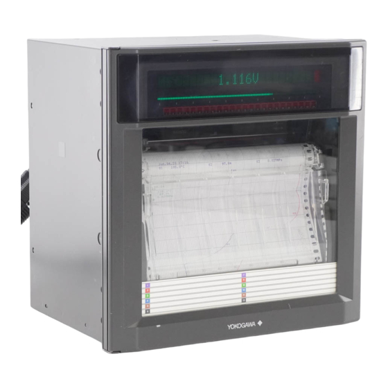
Chapter 4 COMPONENT NAMES AND FUNCTIONS This chapter describes the names of components, together with a short summary of their functions. Figure 4.1 External View (pen model) 4 - 1 IM 4H3B1-01E... -
Page 27: Front Panel
4.1 Front Panel Figure 4.2 Front Panel (4 pen model) 1 Power switch Pressing this button will result in switching the power ON or OFF. 2 Keyboard The keyboard consists of six keys: (RCD-key) Pressing this key will result in starting or stopping the recording. (Menu-key/Esc-key) MENU The MENU function is to select the type of display (see 5.3.8), to start SET UP List... - Page 28 4.1 Front Panel ALARM (Ack-key/Cursor Down-key) The ‘ACK’-function is used to acknowledge alarms. Note that this function is only effective if the alarm relay is in the hold-mode (see 5.3.7), and if the indicator status is in the hold-mode (see 5.3.7). When you press this key in case an alarm occurs and the ALM-indicator is flashing, the current alarm situation will be indicated and the relay will be reset.
-
Page 29: Display
4.2 Display AUTO Figure4.3a Display (4 pen model) AUTO Figure 4.3b Display (dot model) 1 5 × 7 dot matrix (20 characters) Used for data display, clock display, monitor display and setting display (see also 5.3.8). Data display: Channel No. or tag, type of alarm, measured data, units Clock display: (year, month, day) and (hour, minutes, seconds) Monitor display:... -
Page 30: Daily Operation
5.1 How to Switch the Power ON/OFF Chapter 5 DAILY OPERATION This chapter describes the daily operation of the µR1800, excluding settings. Please read this chapter carefully before operation. 5.1 How to Switch the Power ON/OFF The power switch is located behind the door, at the front side, in the middle of the lower front (see figure 5.1a.). -
Page 31: How To Install (& Replace) Chart, Pens, Ribbon Cassette And Battery
5.2 How to Install (& Replace) Chart, Pens, Ribbon Cassette and Battery 5.2.1 How to Load (& Replace) the Chart 1 Open the front door of the unit. 2 The power can be either ‘ON’ or ‘OFF’, but recording should be ‘OFF’. 3 Fan chart paper thoroughly at both ends before loading. - Page 32 5.2 How to Install (& Replace) Chart, Pens, Ribbon Cassette and Battery 8 Place the rear chart guide plate back into position. Press the rear chart guide plate down and towards you and load the chart. 9 Place the front transparent chart guides back into position (see figure 5.5). Figure 5.5 10 Replace the chart paper compartment back into the unit.
-
Page 33: How To Install (& Replace) Pens And Ribbon Cassette
5.2.2 How to Install (& Replace) Pens and Ribbon Cassette In case of felt-tip pens: Normal procedure: 1 Open the front door and make sure the recording is not in progress (by pressing the RCD-key; power can be either ‘ON’ or ‘OFF’). 2 Swing up the display by grasping and pulling the tabs located at the lower left and right corner. - Page 34 5.2 How to Install (& Replace) Chart, Pens, Ribbon Cassette and Battery In case of plotter pen: 1 Open the front door and make sure the recording is not in progress (by pressing the RCD-key; power can be either ‘ON’ or ‘OFF’). 2 Swing up the display by grasping and pulling the tabs located at the lower left and right corner.
-
Page 35: How To Replace The Battery
5.2.3 How to Replace the Battery The ‘BAT’ indicator on the VFD-display can either remain illuminated or flash. In case of illumination, the lithium battery needs to be replaced. However, this battery will last for ten years under normal operation conditions. For replacement, please contact the nearest Sales &... -
Page 36: Basic Operation (Operation Mode)
5.3 Basic Operation (Operation Mode) 5.3 Basic Operation (Operation Mode) 5.3.1 How to Start/Stop the Recording Pressing the RCD-key will cause the recording to start or stop. However, if the Start/ Stop function is controlled by remote control, this key will not work. (For the status of the initial recording settings, see 6.5) 5.3.2 How to Feed the Chart The paper can be fed by operating the FEED-key. -
Page 37: How To Get A List Printout
5.3.4 How to Get a List Printout A list printout contains: • date, time and chart speed (1 & 2) and in case of the dot model, the trend recording interval. • Ch.No. / tag / range / span / scaling values / unit •... - Page 38 5.3 Basic Operation (Operation Mode) Figure 5.11b List Printout Example in case of Dot Model 5 - 9 IM 4H3B1-01E...
-
Page 39: How To Get A Set Up List Printout
5.3.5 How to Get a SET UP List Printout A SET UP list printout contains: • initial settings; analog recording • initial settings; digital printing • initial settings; alarms • initial settings; burnout, RJC and others • initial settings; options, if installed. To get the SET UP list printout, proceed as follows: Press the MENU-key and select the ‘MENU=SELECT_FUNCTION’... - Page 40 5.3 Basic Operation (Operation Mode) Figure 5.12b SET UP List Printout Example in case of Dot Model 5 - 11 IM 4H3B1-01E...
-
Page 41: How To Get A Message Printout
5.3.6 How to Get a Message Printout The contents of a message must be entered first. To set or change a message, see 8.2.3. To get a message printed on the chart, proceed as follows: Press the MENU-key and select the ‘MENU=SELECT_FUNCTION’ display using the UP/DOWN-keys. -
Page 42: How To Acknowledge An Alarm
5.3 Basic Operation (Operation Mode) 5.3.7 How to Acknowledge an Alarm When an alarm occurs, the output relays (if installed) will be activated and the alarm indicator will behave as described below (see also figure 5.14): Non-hold Type (for hold/non-hold selection, see 9.1.4 and 9.1.5): when alarm occurs: the output relay will be activated the indicator will lighten... -
Page 43: How To Select The Display
5.3.8 How to Select the Display Four different displays can be selected. These are: DISPLAY AUTO: Channel number or tag, measured values and units will appear on the display alternately. Every channel will be shown for approximately 2 sec. If the input is greater than the upper limit of the recording span, will appear. - Page 44 5.3 Basic Operation (Operation Mode) How to select the desired display is described below. Starting from the basic operation display, press the MENU-key. Select the display ‘MENU=SELECT_DISPLAY’ using the UP/DOWN-keys. Then press the ENT-key. You have now entered the following flow: DISPLAY_AUTO DISPLAY_MANUAL MANUAL CH=?
-
Page 45: How To Cope With Fail/Chart End
5.3.9 How to Cope with FAIL/Chart End When equipped with this option and the chart reaches its end or a CPU-error occurs, the output relay will be activated. There is one output relay for Chart end detection, and one for FAIL detection. For the wiring, see 3.2.5. CHART END: When there are approx. -
Page 46: How To Use The Key-Lock
5.4 How to Use the Key-lock 5.4 How to Use the Key-lock In order to use this function, the settings for the key-lock must be set to ‘USE’. See 9.10. The key-lock is located in the keyboard at the top side. The keyboard is disabled when the plastic key is removed from the key-hole (see figure 5.15). -
Page 47: How To Enter Settings
6.1 Explanation of Modes Chapter 6 HOW TO ENTER SETTINGS This chapter describes the idea behind the settings of the µR1800 Recorder. It is important to read this chapter carefully before entering or changing settings for the first time. 6.1 Explanation of Modes To make the operation of the µR1800 Recorder as easy as possible, the operation and setting are broken down into three modes. -
Page 48: Concept Of Setting Parameters
6.2 Concept of Setting Parameters DISPLAY The user interface is interactive, which means that you will be asked to enter the necessary data. All data can be entered using the keyboard. When entering data, the functions which are pictured above the actual keys are valid. The display usually consists of two parts: SET=RANGE menu... -
Page 49: Flow Charts
6.3 Flow Charts MENUS In the paragraphs where the setting procedures are explained, you will find menus, like for example (as in chapters 7 and 8): RANGE SKIP ALARM VOLT UNIT CHART CLOCK COPY DELT SQRT These menus will not be shown on the actual display. These are to make clear which steps need to be taken to set that parameter. -
Page 50: Flow Chart Of Set Mode
6.3.2 Flow Chart of SET Mode This flow can be entered by pressing the MENU-key for three seconds. VOLT RANGE SPAN LEFT SPAN RIGHT (7.1) RANGE CH.No. TYPE SPAN LEFT SPAN RIGHT TYPE SPAN LEFT SPAN RIGHT DI TYPE DELTA REFERENCE CHANNEL SPAN LEFT SPAN RIGHT... -
Page 51: Flow Chart Of Set Up Mode
6.3 Flow Charts 6.3.3 Flow Chart of SET UP Mode This flow can be entered by turning ON the power while pressing the ENT-key. (9.1) ALARM REFLASH ON/OFF AND/OR RELAY ENERGIZE/DE-EN RELAY HOLD/NONHOLD SAMPLE r TIME INDICATOR HOLD/NONHOLD SAMPLE R TIME ALARM HYSTERESIS (9.2.1) A/D FREQUENCY... -
Page 52: Setting Parameters In Set Mode
6.4 Setting Parameters in SET Mode Setting Parameters Values Remarks RANGE MODE VOLT 20mV 60mV 200mV DC voltage input Thermocouple input Input by Resistance Temperature Detector Digital Input LEVL CONT LEVL: voltage input CONT: contact input DELT Differential computation Assigning a different scale VOLT SQRT 20mV... -
Page 53: List Of Initial Setting Values
6.5 List of Initial Setting Values 6.5 List of Initial Setting Values SET Mode RANGE VOLT (–2.000V to 2.000V) ALARM UNIT all spaces CHART 25 mm/h TREND AUTO ZONE 0 to 180mm PARTIAL PRINT all spaces MESSAGE all spaces CHART2 25 mm/h SET UP Mode Display... -
Page 54: Basic Settings
7.1 How to Set Input Range and Recording Span Chapter 7 BASIC SETTINGS This chapter explains how to perform the settings of: (Initial values are given in parentheses.) 7.1 Input range and recording span (VOLT, –2V to +2V) 7.2 Alarms (OFF) 7.3 Units (all spaces) 7.4 Chart speed (25 mm/h) 7.5 Clock... -
Page 55: Skip Setting
7.1.1 SKIP Setting Unused channels can be skipped, which means that these channels will not be measured, recorded or displayed. MENU: RANGE SKIP ALARM VOLT UNIT CHART CLOCK COPY DELT SQRT SETTING PROCEDURE: Press the MENU-key for three seconds to enter the SET mode. SET=RANGE Select the ‘SET=RANGE’... -
Page 56: Voltage Measurement Setting (Volt Setting)
7.1 How to Set Input Range and Recording Span 7.1.2 Voltage Measurement Setting (VOLT Setting) In the case that the measured signal is a DC-voltage, the range can be set as follows: MENU: RANGE SKIP RANGE LEFT RIGHT ALARM VOLT 0.000 2.000 UNIT... -
Page 57: Thermocouple And Resistance Temperature Detector Setting (Tc, Rtd Setting)
7.1.3 Thermocouple and Resistance Temperature Detector Setting (TC, RTD Setting) In the case that the measured signal is a TC (Thermocouple) or RTD (Resistance Temperature Detector) the range can be set the same way as if it were a DC-voltage. MENU: RANGE SKIP... -
Page 58: Digital Input Setting (Di Setting)
7.1 How to Set Input Range and Recording Span 7.1.4 Digital Input Setting (DI Setting) If a Digital Input (contact input/voltage level input) is being used, the setting can be done as follows: MENU: RANGE SKIP TYPE ALARM VOLT LEVL UNIT CHART CLOCK... -
Page 59: Difference Computation Setting (Delt Setting)
7.1.5 Difference Computation Setting (DELT Setting) To obtain the difference between the measured values of two channels, proceed as follows. Note that this setting can only be applied if the reference channel is of the VOLT, TC or RTD type. MENU: RANGE SKIP... -
Page 60: Scale Setting (Scl Setting)
7.1 How to Set Input Range and Recording Span 7.1.6 Scale Setting (SCL Setting) To assign a different scale to the measured data, the range can be set as described below. Note that the measured data which can get a different scale must be of the voltage (VOLT), Thermocouple (TC) or Resistance Temperature Detector (RTD) type. -
Page 61: Setting To Obtain Square Root (Sqrt Setting)
7.1.7 Setting to Obtain Square Root (SQRT Setting) To obtain the square root of the measured value, proceed as follows: Note that the measured data of which the square root can be taken, can only be of the voltage type. To assign a unit, refer to UNIT setting (7.3). MENU: RANGE SKIP... - Page 62 7.1 How to Set Input Range and Recording Span EXPLANATION OF SQUARE ROOT: The µR1800 uses the following square rooting-method: Let us define the items as follows: = minimum value of recording span (LEFT) = maximum value of recording span (RIGHT) = minimum value of scale (SCL LEFT) = maximum value of scale (SCL RIGHT) = input voltage...
-
Page 63: How To Set Alarms
7.2 How to Set Alarms Alarms can be set on the measured data of any channel. If an alarm is set, and an alarm occurs, the ALM indicator will be illuminated and alarm printout will occur. If equipped with the optional alarm output relays, these will be activated by the occurrence of an alarm. - Page 64 7.2 How to Set Alarms The initial value is ‘OFF’ for all channels and all levels. To set an alarm, proceed as follows: MENU: RANGE LEVEL ALARM ON/OFF TYPE VALUE RELAY ON/OFF RELAY No. ALARM 2.000 UNIT CHART CLOCK COPY SETTING PROCEDURE: Press the MENU-key for three seconds to enter the SET mode.
-
Page 65: How To Assign Units
7.3 How to Assign Units When you are using scaling (SCL) or the square root setting (SQRT), it is possible to assign a different unit to the scales. Up to six characters can be set. Note that only four characters will be shown on the display when tags are specified. The initial value is all spaces. -
Page 66: How To Set The Chart Speed
7.4 How to Set the Chart Speed 7.4 How to Set the Chart Speed The chart speed can be set within a range of 1 to 12000 mm/h, depending on your model. The initial value is 25 mm/h. To set the chart speed, proceed as follows: MENU: RANGE SPEED... -
Page 67: How To Set The Clock
7.5 How to Set the Clock To set the date and the time of the internal clock, proceed as follows: MENU: RANGE DATE TIME ALARM 92/06/30 13:30:00 UNIT CHART CLOCK COPY SETTING PROCEDURE: Press the MENU-key for three seconds to enter the SET mode. SET=CLOCK MENU Select the ‘SET=CLOCK’... -
Page 68: How To Copy Channel Settings To Another Channel
7.6 How to Copy Channel Settings to Another Channel 7.6 How to Copy Channel Settings to Another Channel It is possible to copy settings from one channel to another. If executed, all settings concerning range, alarm, unit, zone recording, partial expanded recording, periodic printout and tag will be copied. -
Page 69: How To Set The Remote Rjc (For /N5 Model)
7.7 How to Set the Remote RJC (For /N5 Model) When measuring a temperature by thermocouple (TC) and the object of measurement is located at a big distance, it is possible to measure the temperature without using a lot of expensive TC wires by establishing a relay terminal near the measurement object. - Page 70 7.7 How to Set the Remote RJC (For /N5 Model) MENU RANGE SKIP RRJC SPAN-L SPAN-R ALARM VOLT MATH 800.0 UNIT CHART CLOCK COPY DELT SQRT SETTING PROCEDURE: Press the MENU-key for three seconds to enter the SET mode. SET=RANGE MENU Select the ‘SET=RANGE’...
-
Page 71: Chapter 8 Auxiliary Settings (Aux)
8.1 Settings for Analog Recording Chapter 8 AUXILIARY SETTINGS (AUX) This chapter describes auxiliary settings, which are normally kept at their initial values but, in order to use the many functions of the µR1800, might be changed. They are grouped into 8.1 Settings for analog recording 8.2 Settings for digital printing 8.3 How to set the chart speed used when change-on-alarm or remote control is... -
Page 72: How To Adjust The Trend Recording Format
8.1.1 How to Adjust the Trend Recording Format The µR1800 prints in FIX or AUTO mode. In FIX mode, dot printing is performed with a constant interval regardless of the chart speed (approx. 10s for 6 dot, 15s for 12 dot, 20s for 18 dot and 30s for 24 dot model). AUTO mode is provided to prevent the chart from being damaged during repetitive dot printing. -
Page 73: How To Set Zone Recording
8.1 Settings for Analog Recording 8.1.2 How to Set Zone Recording Zone recording enables you to define different bands (zones) for each channel, so the recording traces will not overlap during analog recording. The initial value is ‘0 to 180mm’. To set the zones, proceed as follows: MENU: RANGE... -
Page 74: How To Set Partial Expanded Recording
8.1.3 How to set Partial Expanded Recording Partial expanded recording enables you to compress a part of the recording span, in order to examine the expanded (other) part of the range in more detail. The initial value is ‘OFF’. To set partial expanded recording, proceed as follows: MENU: RANGE TREND... - Page 75 8.1 Settings for Analog Recording EXPLANATION: The next figures show the recordings before and after the above settings have been completed: –6 –5 –4 –3 –2 –1 6 (V) Measured value Recording chart width (180mm) % of full span Figure 8.2 Normal Recording Example –6 –5 –4 –3 –2 –1 6 (V) Measured value...
-
Page 76: Settings For Digital Printing
8.2 Settings for Digital Printing This paragraph describes how to select the periodic printout ON/OFF, how to set a tag and how to set a message. Initial values are: PRINT all spaces all spaces 8.2.1 How to Select the Periodic Printout ON/OFF The printing of channel No., tag and the measured values in the periodic printout can be selected ON/OFF per channel. - Page 77 8.2 Settings for Digital Printing To select this periodic printout ON or OFF, proceed as follows: MENU: RANGE ZONE Periodic Printout ALARM PART UNIT PRINT CHART CLOCK COPY CHART 2 SETTING PROCEDURE: Press the MENU-key for three seconds to enter the SET mode. SET=AUX MENU Select the ‘SET=AUX’...
-
Page 78: How To Set A Tag
8.2.2 How to Set a Tag The following setting enables you to set tags to be recorded instead of the usual channel numbers. Tags will appear on the display, in the periodic printout, manual printout and in the alarm printout. One tag can be set for every channel. The maximum length is seven characters. -
Page 79: How To Set Messages
8.2 Settings for Digital Printing 8.2.3 How to Set Messages The following setting enables you to set the messages. Up to five messages can be set, each of up to 16 characters. Messages can be printed onto the chart using the keyboard, or by remote control which is optional. -
Page 80: How To Set The Chart Speed Used When Change-On-Alarm Or Remote Control Is Selected
8.3 How to Set the Chart Speed Used When Change-on-alarm or Remote Control is Selected The following describes the way to use a second chart speed which is activated by remote control or by the occurence of alarms. This function enables you to record data in more detail following a remote control trigger or following the occurence of an alarm. -
Page 81: How To Change Initial Settings For The Alarm Function
9.1 How to Change Initial Settings for the Alarm Function Chapter 9 CHANGING INITIAL SETTINGS Chapter9 CHANGING INITIAL SETTINGS This chapter describes how to change initial settings. These settings are entered during the manufacturing of the recorder and seldom need to be changed. See 6.3.3 for flow chart. -
Page 82: How To Select The Reflash Function On/Off
9.1.1 How to Select the Reflash Function ON/OFF Reflash is a function to indicate repeating alarm occurrences among a group of alarms sharing the same output relay. When the optional alarm output relays are not installed, data entry will be ignored. Note that only I01 to I03 (which should be assigned in the alarm setting also) can be used for the reflash function. -
Page 83: How To Select The Output Relay To Be Of And/Or Type
9.1 How to Change Initial Settings for the Alarm Function 9.1.2 How to Select the Output Relay to be of AND/OR Type The (optional) output relays can be specified to be AND or OR type, which is necessary when a group of alarms shares the same output relay. The initial value is ‘NONE’, which means that all relays are OR output. -
Page 84: How To Select The Output Relay To Be Energizing/De-Energizing On Alarm
9.1.3 How to Select the Output Relay to be Energizing/De-energizing on Alarm The alarm output relays can be selected to be energizing or de-energizing on alarm. Using de-energizing, alarm output relay is activated either when an alarm occurs, or when power off occurs (common for all relays). This enables simple monitoring of power supply. -
Page 85: How To Select The Alarm Output Relay To Be Of Hold/Non-Hold Type
9.1 How to Change Initial Settings for the Alarm Function 9.1.4 How to Select the Alarm Output Relay to be of HOLD/NON-HOLD Type You can select whether or not to hold alarm output relays until reset. The initial value is ‘NON-HOLD’, and common for all relays. NON-HOLD: Output relay turns ON and OFF together with alarm. -
Page 86: How To Select The Alarm Indicator To Be Of Hold/Non-Hold Type
9.1.5 How to Select the Alarm Indicator to be of HOLD/NON-HOLD Type You can select whether or not to hold the indicator until reset. The initial value is ‘NON-HOLD’, and common for all alarms. NON-HOLD: Indicator turns ON and OFF together with alarm. Alarm ON Alarm OFF Ind. -
Page 87: How To Set The Sampling Interval For Rate-Of-Change Alarms
9.1 How to Change Initial Settings for the Alarm Function 9.1.6 How to Set the Sampling Interval for Rate-of-change Alarms You can change the sampling interval for rate-of-change alarms by the following setting (common for all alarms). The initial value is ‘01’ sample (the actual time depends on the model and A/D frequency;... -
Page 88: How To Select Alarm Hysteresis On/Off
9.1.7 How to Select Alarm Hysteresis ON/OFF The alarm hysteresis is the difference between the levels of alarm occurence and reset. You can choose between two levels of hysteresis: 0% (=OFF) and approx. 0.5% of the recording span (=ON) (common for all alarms). The inititial value is ‘ON’. -
Page 89: How To Change Initial Settings For The Input
9.2 How to Change Initial Settings for the Input 9.2 How to Change Initial Settings for the Input This paragraph describes how to change initial settings for the input. 9.2.1 How to set the A/D integration time (initial value = ‘AUTO’ for pen model, and ‘100 ms’... -
Page 90: How To Set Upscale/Downscale Tc Burnout
9.2.2 How to Set Upscale/Downscale TC Burnout The purpose of the following setting is to specify where the pens will move in case of a TC-burnout. You can choose from moving to the right (UP) or to the left (DOWN). This is common for every channel. -
Page 91: How To Set Internal Or External Rjc
9.2 How to Change Initial Settings for the Input 9.2.3 How to Set Internal or External RJC The purpose of the following setting is to select whether internal or external reference junction compensation values are used. In the case of INTernal, the reference junction compensation is based on the internal RJC circuit. -
Page 92: How To Select The Input Filter (Pen Model)
9.2.4 How to Select the Input Filter (Pen Model) Noise in the measured signal can be suppressed in the final measurement by using an input filter. This is sometimes referred to as signal damping. The purpose of this setting is to select for each channel whether or not to use a filter, and if so, to select a time constant of damping. -
Page 93: How To Select A Moving Average (Dot Model)
9.2 How to Change Initial Settings for the Input 9.2.5 How to Select a Moving Average (Dot Model) Noise in the measured signal can be suppressed in the final measurement by computing a moving average. It is possible to record a moving average calculated over the previous X samples, selectable from the previous 2 samples up to the previous 16 samples. -
Page 94: How To Change Initial Settings For Analog Recording
9.3 How to Change Initial Settings for Analog Recording This paragraph describes how to change initial settings for analog recording. 9.3.1 How to select pen offset compensation ON/OFF (initial value = ‘OFF’) (pen model) 9.3.2 How to assign different colors to channels (dot model) Related settings concern the way to adjust the position of pens and printer carriage, which is described in chapter 11 (see 11.3 and 11.4). -
Page 95: How To Assign Different Colors To Channels (Dot Model)
9.3 How to Change Initial Settings for Analog Recording 9.3.2 How to Assign Different Colors to Channels (Dot Model) You can assign any of the six provided colors to any channel. The initial setting is as follows: ch.1, 7, 13, 19 = purple ch.2, 8, 14, 20 = red ch.3, 9, 15, 21 = green ch.4, 10, 16, 22 = blue... -
Page 96: How To Change Initial Settings For Digital Printouts
9.4 How to Change Initial Settings for Digital Printouts This paragraph describes how to change initial settings for digital printouts. (Note that the selection to trigger the recording to start/stop is explained in 9.9) 9.4.1 How to select channel numbers or tag printout (initial value = ‘CH’) 9.4.2 How to select scales printout ON/OFF (initial value = ‘ON’) 9.4.3 How to select the new chart speed printout ON/OFF (initial value = ‘OFF’) 9.4.4 How to select the record start time printout ON/OFF (initial value = ‘OFF’) -
Page 97: How To Select The New Chart Speed Printout On/Off
9.4 How to Change Initial Settings for Digital Printouts 9.4.3 How to Select the New Chart Speed Printout ON/OFF You can select the new chart speed printed on the chart when the chart speed changes. Note that the chart speed will not be printed when the chart speed exceeds 1500 mm/h. (pen model) or 100 mm/h. -
Page 98: How To Select Alarm Settings And Alarm Printout
9.4.5 How to Select Alarm Settings and Alarm Printout When alarms occur, the channel number, type of alarm and ON/OFF time can be printed on the right side of the chart. It is selectable to get the ON/OFF time of alarms (ON1), the ON time only (ON2) or to get no printout (OFF). - Page 99 9.4 How to Change Initial Settings for Digital Printouts If you selected INT: The display ‘START=00:00’ will appear. Specify the reference time of the first periodic printout using the UP/DOWN-keys. Press the ENT-key. Note that you cannot specify minutes. Specify which interval between the periodic printouts you prefer. Choose from AUTO (and the interval depends on the chart speed) or MAN (and you can specify the interval yourself).
-
Page 100: How To Select The Type Of Bargraph
9.5 How to Select the Type of Bargraph The µR1800 can display two types of bargraphs: 1) Left-referenced (%) bargraph (NORML) The left side of the bargraph represents the left span value, the right side of the bargraph represents the right span value. The display will show the measured value as a percentage of the span. -
Page 101: How To Change The Temperature Unit (For Usa)
9.6 How to Change the Temperature Unit (for USA) 9.6 How to Change the Temperature Unit (for USA) For the TC or RTD type, the µR1800 will automatically append the temperature unit (˚C or ˚F). The initial value is ‘˚C’, and common for all channels. SETTING PROCEDURE: Enter the SET UP Mode by turning ‘ON’... -
Page 102: How To Change Initial Settings For The Remote Option
9.8 How to Change Initial Settings for the REMOTE Option This paragraph describes the way to change initial settings for the REMOTE option. The settings concerning the REMOTE option are always accessible, and data entry will be ignored if your µR1800 is not equipped with this option. The /R1 option allows you to execute functions on the µR1800 by a remote trigger (contact input). -
Page 103: How To Select To Trigger The Recording To Start/Stop
9.9 How to Select to Trigger the Recording to Start/Stop 9.9 How to Select to Trigger the Recording to Start/Stop The start/stop of the recording can be triggered by • the RCD-key on the keyboard (INTernally triggered), or by • remote control input (EXTernally triggered). The initial value is ‘INT’. -
Page 104: How To Change Key-Lock Settings
9.10 How to Change Key-lock Settings You can choose to use the key-lock or not. ‘NOT’ : all keys are operable, even when the key is removed from the key-hole. ‘USE’ : to select to ‘USE’ the key-lock affects the 3 modes in different ways. Operation Mode: •... -
Page 105: Chapter 10 General Specifications
Chapter 10 GENERAL SPECIFICATIONS MODELS 1, 2, 3 and 4 pen; 6 dot, 12 dot, 18dot and 24 dot printing model TYPES DCV : Direct Voltage input 20mV to 20V range. TC : Thermocouple. RTD : Resistance Temperature Detector. : Digital Input (contact or DC Voltage, TTL level). DCA : Direct Current Input (using external shunt resistor (10Ω, 100Ω, 250Ω)). - Page 106 Calculation: Differential computation: Between any two channels, however reference channel No. must be less than measuring channel No. Available for DCV, TC, and RTD range. Both channels must have same range. Linear scaling: Available for DCV, TC and RTD range. (scaling) Scaling limits: –20000 to 20000 Data display &...
- Page 107 PT100 ± (0.15% of rdg + 0.3°C) 0.1°C measurement accuracy pen: dead band: 0.2% of ± (0.3% of recording span) recording span meas. current JPT100 dot: 0.1 mm = 1mA ± (0.3% of rdg + 0.5°C) JPt50 Cu10 (Cu1 to 6) ±...
- Page 108 Recording Period: pen : Continuous for each channel. dot : max. 6 ch./10 sec, 12ch./15 sec, 18ch./20 sec, 24ch./30 sec, AUTO/FIX selectable AUTO : Analog recording interval is depending on the chart speed. : Analog recording interval is set to shortest period. Chart Speed: pen : 5 to 12000 mm/h (82 increments) dot : 1 to 1500 mm/h (1mm step)
- Page 109 Relation between Chart Speed and Intervals of Periodic Printout: Pen Model Dot Model Chart Speed Printing Interval of Periodic Printout Chart Speed Printing Interval of Periodic Printout 6 dot 12 dot 18 dot 24 dot no printout 5 to 9 mm/h 10 to 18 mm/h every 8 hours 20 to 36 mm/h...
- Page 110 Alarm Indication When ALARM ACK-key is Pressed: Non-Hold type: Alarm display is not affected when the ALARM ACK-key is pressed. Hold type: When alarm occurs, alarm indicator will start flashing. After pressing the ALARM ACK-key, the indicator will show the status of the alarm.
- Page 111 EMC Conformity Standard(for standard model except for /P1 model) EMI EN55011: Class A EMS EN50082-2 IEC1000-4-2: Electrostatic Discharge 8 kV(Air ) Performance Criteria B 4 kV(Contact) IEC1000-4-3: Radiated fields 80MHz-1000MHz 10V/m Performance Criteria A (Pen Model: ± 5% of Range) (Dot Model: ±...
- Page 112 Magnetic Field: less than 400AT/m (DC and 50, 60Hz) Noise: Normal Mode (50, 60Hz) Peak value including signal must be less than 1.2 times the measuring range. Peak value including signal must be less than 1.2 times the measuring mV. less than 50mV.
- Page 113 within ±(5% of range) Recording: TRANSPORT and STORAGE CONDITIONS No malfunction will occur under these conditions, however when returning to normal operation conditions, calibration might be necessary. Temperature: –25 to 60°C Humidity: 5 to 95% RH (no condensation) Vibration: 10 to 60Hz, 0.5G Shock: less than 40G (inside packings) OTHER SPECIFICATIONS...
-
Page 114: Chapter 11 Maintenance
11.1 Periodic Maintenance Chapter 11 MAINTENANCE 11.1 Periodic Maintenance Check the recorder operation periodically to keep the recorder in good operation condition. Especially, check the following items and replace consumable parts such as chart, disposable felt-tip pens, fuse and batteries, etc. as needed. •... -
Page 115: Fuse Replacement
11.2 Fuse Replacement Replace the fuse at least once every two years for preventive maintenance. To replace the fuse, turn OFF the main power supply. 1 Remove the chart compartment. Do this as follows: While gently pressing the chart paper compartment lock tab, located in the middle at the lower front, in the direction of the arrow, swing and lift the compartment from the unit. -
Page 116: Pen Adjustment (Pen Model)
11.3 Pen Adjustment (Pen Model) 11.3 Pen Adjustment (Pen Model) It is recommended to adjust the position of the pens once a year. To adjust the pens, proceed as follows: • Allow a warm-up time for the recorder of at least 30 minutes. Check that the ambient temperature and humidity are within Normal Operating Conditions (see chapter 10 ‘General Specifications’). -
Page 117: Printer Carriage Adjustment (Dot Model)
11.4 Printer Carriage Adjustment (Dot Model) It is recommended to adjust the position of the carriage once a year. To adjust the carriage, proceed as follows: • Allow a warm-up time for the recorder of at least 30 minutes. Check that the ambient temperature and humidity are within Normal Operating Conditions (see chapter 10 ‘General Specifications’). -
Page 118: Calibration
It is recommended to perform a calibration once a year to assure the measuring accuracy. Required instruments: DC Voltage Standard: YOKOGAWA Model 2552 or equivalent. Decade Resistance Box: YOKOGAWA Model 2793-01 or equivalent. Calibration procedure: 1 Connect the calibration instrument to the input terminals of the recorder as shown in figures 11.3, 4 , 5 or 6 and allow the recorder to warm up for at least 30 minutes. - Page 119 When calibrating the recorder, the input voltage without subtracting the compensation voltage should be applied (For example, use the YOKOGAWA Model T-MJ reference Junction compensator shown above).
-
Page 120: Cleaning The Plotter Carriage Shaft (Pen Model)
11.6 Cleaning the Plotter Carriage Shaft (Pen Model) 11.6 Cleaning the Plotter Carriage Shaft (Pen Model) When using the recorder under normal operating conditions, periodically inspect the plotter carriage shaft for dirt. It is recommended that the plotter carriage shaft be cleaned at least once a year. -
Page 121: Chapter 12 Troubleshooting
12.1 Error Message Table Chapter 12 TROUBLESHOOTING This chapter describes the cause and countermeasures to be taken in case errors or failures occur. 12.1 Error message table 12.2 Troubleshooting flow chart 12.1 Error Message Table Error Message Error Description Countermeasure (on display) ERROR 001 Main recorder related errors other than those below... -
Page 122: Troubleshooting Flow Chart
12.2 Troubleshooting Flow Chart Neither the pen nor the chart moves. Is the power switch ON? Turn ON properly Does the switch work properly? Are the connections Connect properly at the power supply terminal correct? Supply properly (Specified Is the power being supplied voltage and frequency) properly? Contact your nearest Sales &... - Page 123 12.2 Troubleshooting Flow Chart The input value and measured value are very different. (e.g. pens are staying at 0% or 100% of the chart, big fluctuations.) Does the input satisfy the Meet the specifications specifications? (signal source resistance, etc.) Are the span and range Adjust the span and range settings correct? Ground the recorder properly.
- Page 124 Display and functions do not work properly. Ground the recorder properly. Use shielded wire for input and communication. Insert an isolated transformer into the power line. Is the input free of noise? Insert a power line filter into the power line. In case a reactive road is used as an alarm output line, use a surge suppressor in the alarm line.
- Page 125 TERMINOLOGY allowable input voltage The maximum input voltage that can be applied to the input terminals burnout Failure of a device due to excessive heat common-mode rejection ratio The ability of an amplifier to cancel a common-mode voltage common-mode voltage A voltage that appears equally and in phase from each signal conductor with respect to ground.
- Page 126 scaling Recording of an input in terms of the engineering variable shunt resistor Resistor used at the input terminal to transfer a current into a voltage step response The behavior of a system when its input signal is zero before a certain time and is equal to a nonzero value after this time thermocouple A pair of dissimilar conductors joined at two points so that an electromotive...
- Page 127 INDEX relation between printouts and ... 10 - 4, 7 - 13 relation between printing interval of periodic A/D integration time ..........9 - 9 printout and ........7 - 13, 10 - 4 abort SET UP settings ......... 6 - 1, 9 - 2 setting ............
- Page 128 SET UP mode ..........6 - 5 switching between ........... 6 - 1 fuse mounting ............... 3 - 2 part number ............. 2 - 2 moving average ..........9 - 13 replacement ........... 11 - 2 NON-HOLD High/Low limit alarm ......... 7 - 10 alarm relay ...........
- Page 129 rate-of-change High/Low alarm ......7 - 10 printout ............5 - 10 SET UP Mode ............6 - 1 indicator ............4 - 4 signal damping............ 9 - 12 key ..............4 - 2 spares ..............2 - 2 recording square root (SQRT) ..........
Need help?
Do you have a question about the µR1800 and is the answer not in the manual?
Questions and answers