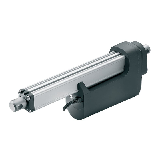
Linak TECHLINE LA36 Connection Diagram
Endstop signals and absolute positioning - pwm
Hide thumbs
Also See for TECHLINE LA36:
- User manual (95 pages) ,
- Manual (20 pages) ,
- Connection diagram (4 pages)
Subscribe to Our Youtube Channel
Summary of Contents for Linak TECHLINE LA36
- Page 1 Actuator LA36/LA37 Endstop signals and absolute positioning - PWM Connection diagram LINAK.COM/TECHLINE...
- Page 2 F O R M O U N T I N G I N S T R U C T I O N S A N D G U I D A N C E I N U S A G E , P L E A S E S E E T H E R E L E V A N T U S E R ’ S M A N U A L S 2019 © LINAK A/S...
- Page 3 I/O Specifications Endstop signals and absolute positioning - PWM Input/Output Specification Comments Description The actuator can be equipped with electronic circuit that gives an analogue feedback signal when the actua- tor moves. See connection diagram, figure above Brown 12, 24 or 36* VDC (+/-) To extend actuator: *Only available on LA36 Connect Brown to positive...
- Page 4 While LINAK uses its best efforts to fulfil orders, LINAK cannot, for the same reasons as mentioned above, guarantee the availability of any particular product. Therefore, LINAK reserves the right to discontinue the sale of any product displayed on its website or listed in its catalogues or other written material drawn up by LINAK.


Need help?
Do you have a question about the TECHLINE LA36 and is the answer not in the manual?
Questions and answers