Table of Contents
Advertisement
Quick Links
SECTION I:
1.1
1.2
1.3
Specifications1-1
1.4
SECTION II:
2.1
General2-1
2.2
2.3
SECTION III:
3.1
Introduction3-1
3.2
Amplifier Section3-1
3.3
Power Supply3-2
3.4
Remote Control3-5
SECTION IV:
4.1
General Maintenance4-1
4.2
Disassembly Procedure4-1
4.3
Troubleshooting4-2
4.4
SECTION V:
5.1
Introduction5-1
5.2
Ordering Information5-1
5.3
Non-Listed Parts5-1
5.4
Circuit Designators5-1
5.5
Manufacturer's Abbreviation Listing5-3
5.6
Master List5-3
5.7
Schematics and Bills of Material5-3
SECTION VI:
6.1
Level of Maintenance6-1
TABLE OF CONTENTS
REPLACEABLE PARTS
RECOMMENDED SPARE PARTS
WARRANTIES: LIMITATION OF LIABILITIES
Advertisement
Table of Contents

Subscribe to Our Youtube Channel
Related Manuals for AR 25W1000M7


Summary of Contents for AR 25W1000M7
-
Page 1: Table Of Contents
TABLE OF CONTENTS SECTION I: GENERAL INFORMATION General Description1-1 Power Supplies1-1 Specifications1-1 Performance Verification1-1 SECTION II: OPERATING INSTRUCTIONS General2-1 Amplifier Operation2-2 Remote Control2-3 SECTION III: THEORY OF OPERATION Introduction3-1 Amplifier Section3-1 Power Supply3-2 Remote Control3-5 SECTION IV: MAINTENANCE General Maintenance4-1 Disassembly Procedure4-1 Troubleshooting4-2 Servicing Etched Circuit Boards4-2... -
Page 2: General Information
Solid state technology is used exclusively to offer significant advantages in reliability and cost. A Model 25W1000M7 used with a frequency swept signal source will provide 20 watts of linear swept power output from 25 MHz to 1000 MHz. Typical applications include... -
Page 3: Operating Instructions
OPERATING INSTRUCTIONS GENERAL Operation of the Model 25W1000M7 broadband amplifier is quite simple. The input signal, whether swept or fixed in frequency, is fed into the jack marked "INPUT" and the amplifier output signal is taken from the jack labeled "OUTPUT". The unit is turned on by activating the power switch. -
Page 4: Amplifier Operation2-2
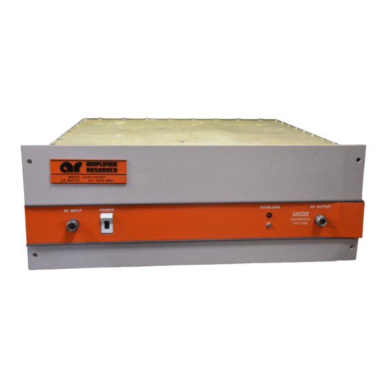
REV - AMPLIFIER OPERATION Figure 2.1 shows the Model 25W1000M7 Amplifier in pictorial form. Figure 2.1 "Amplifier Operation" TURN ON SEQUENCE: Connect input signal to "INPUT" connector. Connect load to "OUTPUT" connector. Select either 120/240 VAC operation by means of switch located on rear of unit. -
Page 5: Remote Control2-3
LED's may be used for function indicators. The local/remote push button switch at the rear panel of the 25W1000M7 must be in the remote (LED on) position, and the power switch on the front panel must be on for the unit to operate. -
Page 6: Theory Of Operation
The self-contained power supply employs a full wave rectifier, two (2) integrated circuit regulators to provide stable, low ripple, regulated output voltages. AMPLIFIER OPERATION The Model 25W1000M7 contains a low level driver amplifier and a final amplifier. Each will be explained. 3.2.1 Low Level Driver Amplifier Refer to Block Diagram Number 1006273, "RF Amplifier Assembly", Schematic Diagram... - Page 7 REV - 3.2.1 Low Level Driver Amplifier (Continued) The first stage is connected in the common emitter mode with the emitter connected to ground through three (3) resistors. This configuration allows the selection of the emitter resistors to achieve the desired stage gain. The collector voltage (+) is supplied to this stage from the transistor immediately above it (refer to Schematic Diagram Number 1006303, "RF Board Assembly").
- Page 8 Rev- POWER SUPPLY SECTION (Continued) CAUTION: DO NOT CONNECT UNIT TO 240 VAC MEASURED LINE TO LINE. TO DO SO WOULD RESULT IN ONE SIDE OF THE LINE NOT BEING FUSED, CREATING A HAZARDOUS SITUATION. THE 240 VAC FEATURE IS DESIGNED PRIMARILY FOR USE IN COUNTRIES HAVING 240 VAC MEASURED LINE TO NEUTRAL.
- Page 9 REV -...
- Page 10 Overload Reset. The Amplifier Research Computer Interface unit Model CP2001 may be utilized to provide the above functions. It can also provide the appropriate interface between the Model 25W1000M7 and any controller-computer having an IEEE-488 bus and appropriate interface. The 25W1000M7 can also be operated remotely with Amplifier Research Model CP3000 which interfaces directly with a computer over the IEEE-488 bus.
- Page 11 Placing S4 in the on position energizes remote enable relay A1A3K1, enabling the remote control unit to turn the Model 25W1000M7 "ON" and "OFF". When remote control is used an interlock connection must be provided between J1-6 and J1-7.
-
Page 12: Maintenance
MAINTENANCE GENERAL MAINTENANCE INFORMATION The Model 25W1000M7 should require very little maintenance since it is a relatively simple instrument. It is built with etched circuit wiring and solid state devices which should ensure long, trouble-free life. However, should trouble occur special care must be taken in servicing to avoid damage to the devices or the etched circuit board. -
Page 13: Servicing Etched Circuit Boards4-2
4.2.3 Remove bottom cover by removing the screws. 4.2.4 Remove circuit board and heat sink by removing the screws at each end of the heat sink. TROUBLESHOOTING The techniques used in troubleshooting solid state instruments are similar to those used in vacuum tube instruments.
Need help?
Do you have a question about the 25W1000M7 and is the answer not in the manual?
Questions and answers