Table of Contents
Advertisement
Available languages
Available languages
Quick Links
Advertisement
Chapters
Table of Contents

Related Manuals for Sartorius PR 6202 Series


Summary of Contents for Sartorius PR 6202 Series
- Page 1 Installation Manual Installationshandbuch Manuel d’installation Mounting Kits for Load Cell PR 6202 PR 6002 9499 053 00211 Edition 2 15.12.2010 Sartorius Mechatronics T&H GmbH, Meiendorfer Str. 205, 22145 Hamburg, Germany Tel:+49.40.67960.303 Fax:+49.40.67960.383...
- Page 2 Please note In any correspondence concerning this instrument, please always quote the type number and serial number as given on the type plate. Important As the instrument is an electrical apparatus, it may be operated only by trained personnel. Maintenance and repairs may only be carried out by qualified personnel. Bitte beachten Bei Schriftwechsel über dieses Gerät wird gebeten, die Typennummer und die Seriennummer anzugeben.
-
Page 3: Table Of Contents
Load Disk Sets PR 6002/00S, ../01S ....................17 Installation ........................... 18 Before the Mounting..........................18 Tightening Torques..........................18 Mounting..............................19 4.3.1 PR 6002/02S, ../03S ..........................19 4.3.2 PR 6002/04S, ../05S, ../10S, ../11S, ../20S, ../21S................20 Check after Installation and Start-Up ..................22 Spare Parts and Accessories....................... 22 Sartorius EN-1... -
Page 4: Safety Instructions
Installation and repair work must be carried out only by qualified personnel. Design Recommendations Position of Load Cells and Contrainers * do not constrain this position EN-2 Sartorius... -
Page 5: Transport Protections
After installation of the mounting kit and before mounting the load cell, the transport protections must be removed. • Release and remove the threaded connection M16 (2). • Lift the upper part of the mounting kit and remove the brackets (1) and the transport bushing (3). Sartorius EN-3... -
Page 6: Internal Lift-Off Protection
Pull out the four tabs on the rubber ring by approx. 15 mm so that the rubber ring is removed from between load disk and load cell. • Then tear or cut off the rubber ring to remove it completely. EN-4 Sartorius... -
Page 7: Technical Data
Installation Manual Mounting Kits PR 6002 Technical Data Scope of Delivery 3.1.1 PR 6002/00S + 01S Pos. Description Load disk Rubber ring for mounting * (not shown) * delivered in a bag Sartorius EN-5... -
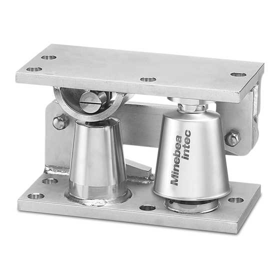
Page 8: Pr 6002/02S + 03S
Mounting Kits PR 6002 Installation Manual 3.1.2 PR 6002/02S + 03S Pos. Description Upper mounting plate Lower mounting plate Rubber ring for mounting * (not shown) * delivered in a bag EN-6 Sartorius... -
Page 9: Pr 6002/04S + 05S
Screw M16 × 100-A2 * Nut M16-A2 * Transport protection (2x) Transport protection Nut ** Bolt ** Lower mounting plate Rubber ring for mounting ** (not shown) * for transport protection (pos. 4) ** delivered in a bag Sartorius EN-7... -
Page 10: Pr 6002/10S + 11S
Screw M16 × 100-A2 * Bolt (2x) Nut M16-A2 * Bolt ** Transport protection (2x) Nut ** Constrainer Lower mounting plate Transport protection Rubber ring for mounting ** (not shown) * for transport protection (pos. 4) ** delivered in a bag EN-8 Sartorius... -
Page 11: Pr 6002/20S + 21S
Lower mounting plate Upper mounting plate Bolt ** Transport protection (2x) Nut ** Transport sleeve Rubber ring for mounting ** (not shown) Screw M16 × 120-A2 * * for transport locking devices (pos. 5) ** delivered in a bag Sartorius EN-9... -
Page 12: Technical Data
Permissible horizontal force in constrainer direction 50 kN 50 kN Horizontal destructive force in constrainer direction >100 kN >100 kN Load cell clearance ±5 mm ±5 mm Material Stainless steel Stainless steel Weight, net 34.5 kg 34.5 kg EN-10 Sartorius... -
Page 13: Dimensions
Installation Manual Mounting Kits PR 6002 Dimensions 3.3.1 PR 6002/02S all dimensions in mm alle Abmessungen in mm toutes les dimensions en mm 3.3.2 PR 6002/03S all dimensions in mm alle Abmessungen in mm toutes les dimensions en mm Sartorius EN-11... -
Page 14: Pr 6002/04S
Installation Manual 3.3.3 PR 6002/04S all dimensions in mm alle Abmessungen in mm toutes les dimensions en mm ø20 (4x) 3.3.4 PR 6002/05S all dimensions in mm alle Abmessungen in mm toutes les dimensions en mm ø20 (4x) EN-12 Sartorius... -
Page 15: Maxiflexlock Pr 6002/10S
Installation Manual Mounting Kits PR 6002 3.3.5 MaxiFLEXLOCK PR 6002/10S all dimensions in mm alle Abmessungen in mm toutes les dimensions en mm ø20 (4x) Sartorius EN-13... -
Page 16: Maxiflexlock Pr 6002/11S
Mounting Kits PR 6002 Installation Manual 3.3.6 MaxiFLEXLOCK PR 6002/11S all dimensions in mm alle Abmessungen in mm toutes les dimensions en mm ø20 (4x) EN-14 Sartorius... -
Page 17: Maxi Flexlock Pr 6002/20S
Installation Manual Mounting Kits PR 6002 3.3.7 Maxi FLEXLOCK PR 6002/20S all dimensions in mm alle Abmessungen in mm toutes les dimensions en mm ø20 (7x) Sartorius EN-15... -
Page 18: Pr 6002/21S
Mounting Kits PR 6002 Installation Manual 3.3.8 PR 6002/21S all dimensions in mm alle Abmessungen in mm toutes les dimensions en mm ø20 (7x) EN-16 Sartorius... -
Page 19: Load Disk Sets Pr 6002/00S
Caution! Material properties and shaping of the load cell and load disk are matching optimally. Load disks from Sartorius must be used! The surfaces for the load disks must be horizontal, flat and rigid, and must be able to withstand the loads encountered during application. If soft layers are inserted between mounting kit and the rigid adapter, additional load equalization plates between mounting kit and soft layer must be provided externally. -
Page 20: Installation
Mounting kit Bolt Washer Tightening torque DIN 4014 or DIN 4017 DIN 7349 PR 6002/02S PR 6002/03S PR 6002/04S PR 6002/05S M12-A2-70 13 × 30 × 6 A2 70 Nm PR 6002/10S PR 6002/11S PR 6002/20S PR 6002/21S EN-18 Sartorius... -
Page 21: Mounting
Position and install the load cell (4) using the rubber ring for mounting, see Chapter 2.4. • Put the weighing object (1) again on the mounting kit, using a required lifting tool. • Remove the rubber ring, see Chapter 2.4. Sartorius EN-19... -
Page 22: Pr 6002/04S, ../05S, ../10S, ../11S, ../20S, ../21S
Tighten the bolts (4) of the upper mounting plate (5) and the bolts (8) of the lower mounting plate (7) with the recommended tightening moment, see Chapter 4.2. • Lift the weighing object (1) approx. 5 mm, using a required lifting tool remove the transport protections (2, 3), see Chapter 2.2. EN-20 Sartorius... - Page 23 Position and install the load cell (10) using the rubber ring for mounting, see Chapter 2.4. • Put the weighing object (1) again on the mounting kit, using a required lifting tool. • Remove the rubber ring, see Chapter 2.4. • Mount the internal lift-off protection (9), see Chapter 2.3 Sartorius EN-21...
-
Page 24: Check After Installation And Start-Up
Spare Parts and Accessories Pos. Description Max. capacity Order number Lift-off protection (stainless steel) 5312 502 18011 Rubber ring for mounting 1…10 t 5312 693 98117 Rubber ring for mounting 25…50 t 5312 693 98118 EN-22 Sartorius... - Page 25 Installation ........................... 18 Vor der Montage ............................18 Anzugsmomente ............................18 Montage ..............................19 4.3.1 PR 6002/02S, ../03S ..........................19 4.3.2 PR 6002/04S, ../05S, ../10S, ../11S, ../20S, ../21S................20 Überprüfung nach dem Einbau und der Inbetriebnahme ............. 22 Ersatzteile und Zubehör ......................22 Sartorius DE-1...
-
Page 26: Sicherheitshinweise
Zwischenlage und dem Einbausatz eine Lastausgleichsplatte vorgesehen werden, die eine gleichmäßige Lasteinleitung in den Einbausatz sicherstellt. Installations- und Reparaturarbeiten dürfen nur durch sachkundige/eingewiesene Fachkräfte erfolgen. Aufbauempfehlungen Anordnung der Wägezellen und Fesselungen * diesen Punkt nicht fesseln DE-2 Sartorius... -
Page 27: Transportsicherungen
Nach der Montage des Einbausatzes und vor der Montage der Wägezelle sind die Transportsicherungen zu entfernen. • Gewindeverbindung M16 (2) lösen und entfernen. • Den oberen Teil des Einbausatzes anheben und die Laschen (1) und die Transporthülse (3) entfernen. Sartorius DE-3... -
Page 28: Interne Abhebesicherung
• Behälter absenken und Montageschrauben anziehen. • Alle Laschen der Einbauhilfe zunächst ca. 15 mm herausziehen, so dass die Einbauhilfe zwischen Druckstück und Wägezelle entfernt wird. • Anschließend die Einbauhilfe durch Reißen oder Schneiden auftrennen und vollständig entfernen. DE-4 Sartorius... -
Page 29: Technische Daten
Installationshandbuch Einbausätze PR 6002 Technische Daten Lieferumfang 3.1.1 PR 6002/00S + 01S Pos. Bezeichnung Druckstück Montagehilfe * (nicht abgebildet) * in einem Beutel mitgeliefert Sartorius DE-5... -
Page 30: Pr 6002/02S + 03S
Einbausätze PR 6002 Installationshandbuch 3.1.2 PR 6002/02S + 03S Pos. Bezeichnung Obere Montageplatte Untere Montageplatte Montagehilfe * (nicht abgebildet) * in einem Beutel mitgeliefert DE-6 Sartorius... -
Page 31: Pr 6002/04S + 05S
(6+7) monté Pos. Bezeichnung Obere Montageplatte Schraube M16 × 100-A2 * Mutter M16-A2 * Transportsicherung (2x) Transportsicherung Mutter ** Schraube ** Untere Montageplatte Montagehilfe ** (nicht abgebildet) * für Transportsicherungen (Pos. 4) ** in einem Beutel mitgeliefert Sartorius DE-7... -
Page 32: Pr 6002/10S + 11S
Obere Montageplatte Hutmutter M12-A2 (4x) Schraube M16 × 100-A2 * Bolzen (2x) Mutter M16-A2 * Schraube ** Transportsicherung (2x) Mutter ** Lenker Untere Montageplatte Transportsicherung Montagehilfe ** (nicht abgebildet) * für Transportsicherungen (Pos. 4) ** in einem Beutel mitgeliefert DE-8 Sartorius... -
Page 33: Pr 6002/20S + 21S
Mutter M16-A2 * Hutmutter M12-A2 (4x) Transportsicherung Lenker Untere Montageplatte Obere Montageplatte Schraube ** Transportsicherung (2x) Mutter ** Transporthülse Montagehilfe ** (nicht abgebildet) Schraube M16 × 120-A2 * * für Transportsicherungen (Pos. 5) ** in einem Beutel mitgeliefert Sartorius DE-9... -
Page 34: Technische Daten
Bruchlast Tragkraft >100 kN >100 kN Zulässige Horizontalkraft in Lenkerrichtung 50 kN 50 kN Bruchlast Horizontal in Lenkerrichtung >100 kN >100 kN Spiel der Wägezelle ±5 mm ±5 mm Material Edelstahl Edelstahl Gewicht, netto 34,5 kg 34,5 kg DE-10 Sartorius... -
Page 35: Abmessungen
Installationshandbuch Einbausätze PR 6002 Abmessungen 3.3.1 PR 6002/02S all dimensions in mm alle Abmessungen in mm toutes les dimensions en mm 3.3.2 PR 6002/03S all dimensions in mm alle Abmessungen in mm toutes les dimensions en mm Sartorius DE-11... -
Page 36: Pr 6002/04S
Einbausätze PR 6002 Installationshandbuch 3.3.3 PR 6002/04S all dimensions in mm alle Abmessungen in mm toutes les dimensions en mm ø20 (4x) 3.3.4 PR 6002/05S all dimensions in mm alle Abmessungen in mm toutes les dimensions en mm ø20 (4x) DE-12 Sartorius... -
Page 37: Maxiflexlock Pr 6002/10S
Installationshandbuch Einbausätze PR 6002 3.3.5 MaxiFLEXLOCK PR 6002/10S all dimensions in mm alle Abmessungen in mm toutes les dimensions en mm ø20 (4x) Sartorius DE-13... -
Page 38: Maxiflexlock Pr 6002/11S
Einbausätze PR 6002 Installationshandbuch 3.3.6 MaxiFLEXLOCK PR 6002/11S all dimensions in mm alle Abmessungen in mm toutes les dimensions en mm ø20 (4x) DE-14 Sartorius... -
Page 39: Maxi Flexlock Pr 6002/20S
Installationshandbuch Einbausätze PR 6002 3.3.7 Maxi FLEXLOCK PR 6002/20S all dimensions in mm alle Abmessungen in mm toutes les dimensions en mm ø20 (7x) Sartorius DE-15... -
Page 40: Pr 6002/21S
Einbausätze PR 6002 Installationshandbuch 3.3.8 PR 6002/21S all dimensions in mm alle Abmessungen in mm toutes les dimensions en mm ø20 (7x) DE-16 Sartorius... -
Page 41: Druckstücksätze Pr 6002/00S
Druckstücksätze PR 6002/00S, ../01S Achtung! Materialeigenschaften und Formgebung der Wägezellen und Druckstücke sind optimal aufeinander abgestimmt. Unbedingt Druckstücke von Sartorius verwenden! Die Flächen für die Druckstücke müssen waagerecht, eben und unnachgiebig sein. Sie müssen die entstehenden Drucklasten aufnehmen können. Wenn weiche Zwischenlagen vorhanden sind, dann sind extern Lastverteilungsplatten vorzusehen! Nennlast der Wägezelle... -
Page 42: Installation
Anzugsmoment kann der folgenden Tabelle entnommen werden. Einbausatz Schraube Scheibe Anzugsmoment DIN 4014 oder DIN 4017 DIN 7349 PR 6002/02S PR 6002/03S PR 6002/04S PR 6002/05S M12-A2-70 13 × 30 × 6 A2 70 Nm PR 6002/10S PR 6002/11S PR 6002/20S PR 6002/21S DE-18 Sartorius... -
Page 43: Montage
Wägezellensitz in den beiden Druckstücken reinigen. • Kontaktflächen zwischen Wägezelle/Druckstücke mit ausreichend Fett versehen. • Wägezelle (4) mit Montagehilfe positionieren und einbauen, siehe Kapitel 2.4. • Wägeobjekt (1) mit entsprechender Hebevorrichtung wieder auf den Einbausatz absenken. • Montagehilfe entfernen, siehe Kapitel 2.4. Sartorius DE-19... -
Page 44: Pr 6002/04S, ../05S, ../10S, ../11S, ../20S, ../21S
Die Schrauben (4) der oberen Montageplatte (5) und die Schrauben (8) der unteren Montageplatte (7) mit empfohlenem Moment festziehen, siehe Kapitel 4.2. • Wägeobjekt (1) mit entsprechender Hebevorrichtung ca. 5 mm anheben und die Transportsicherungen (2, 3) entfernen, siehe Kapitel 2.2. DE-20 Sartorius... - Page 45 Kontaktflächen zwischen Wägezelle/Druckstücke mit ausreichend Fett versehen. • Wägezelle (10) mit Montagehilfe positionieren und einbauen, siehe Kapitel 2.4. • Wägeobjekt (1) mit entsprechender Hebevorrichtung wieder auf den Einbausatz absenken. • Montagehilfe entfernen, siehe Kapitel 2.4. • Interne Abhebesicherung (9) montieren, siehe Kapitel 2.3. Sartorius DE-21...
-
Page 46: Überprüfung Nach Dem Einbau Und Der Inbetriebnahme
Messobjekt zu koppeln. Die gesamte Last muss von den Wägezellen getragen werden. Ersatzteile und Zubehör Pos. Bezeichnung Laststufen Bestellnummer Abhebesicherung (Edelstahl) 5312 502 18011 Montagehilfe 1…10 t 5312 693 98117 Montagehilfe 25…50 t 5312 693 98118 DE-22 Sartorius... - Page 47 Installation ........................... 18 Avant le montage ............................18 Couples de torsion...........................18 Montage ..............................19 4.3.1 PR 6002/02S, ../03S ..........................19 4.3.2 PR 6002/04S, ../05S, ../10S, ../11S, ../20S, ../21S................20 Contrôle après l’installation et la mise en service..............22 Pièces de rechange et accessoires..................... 22 Sartorius FR-1...
-
Page 48: Consignes De Sécurité
Seul un personnel qualifié est autorisé à effectuer les opérations d’installation et les réparations. Recommandations d’installation Disposition des capteurs dans différents cas * ne pas contraindre ce point FR-2 Sartorius... -
Page 49: Sécurités De Transport
Les sécurités de transport doit être enlevée après l’installation du kit de montage et avant le montage du capteur de pesage. • Dévisser et enlever le raccord fileté M16 (2). • Soulever la partie supérieure du kit de montage et enlever les supports (1) et le dispositif de transport (3). Sartorius FR-3... -
Page 50: Protection Interne Contre Le Basculement
Tirer les quatre languettes de l’anneau de montage d’abord d’environ 15 mm de manière à retirer l’anneau d’entre la pièce de pression et le capteur de pesage. • Ensuite, déchirer ou couper l’anneau de montage pour l’enlever entièrement. FR-4 Sartorius... -
Page 51: Caractéristiques Techniques
Manuel d’installation Kits de montage PR 6002 Caractéristiques techniques Contenu de la livraison 3.1.1 PR 6002/00S + 01S Pos. Description Pièce de pression Anneau d’aide de montage * (sans illustration) * livré en sachet plastique Sartorius FR-5... -
Page 52: Pr 6002/02S + 03S
Kits de montage PR 6002 Manuel d’installation 3.1.2 PR 6002/02S + 03S Pos. Description Plaque de montage supérieure Plaque de montage intérieure Anneau d’aide de montage * (sans illustration) * livré en sachet plastique FR-6 Sartorius... -
Page 53: Pr 6002/04S + 05S
Boulon M16 × 100-A2 * Écrou M16-A2 * Sécurité de transport (2x) Sécurité de transport Écrou ** Boulon ** Plaque de montage intérieure Anneau d’aide de montage * (sans illustration) * pour sécurités de transport (pos. 4) ** livré en sachet plastique Sartorius FR-7... -
Page 54: Pr 6002/10S + 11S
Écrou M16-A2* Boulon ** Sécurité de transport (2x) Écrou ** Barre de guidage Plaque de montage intérieure Sécurité de transport Anneau d’aide de montage * (sans illustration) * pour sécurités de transport (pos. 4) ** livré en sachet plastique FR-8 Sartorius... -
Page 55: Pr 6002/20S + 21S
Plaque de montage intérieure Plaque de montage supérieure Boulon** Sécurité de transport (2x) Écrou ** Douille de transport Anneau d’aide de montage * (sans illustration) Boulon M16 × 120-A2* * pour sécurités de transport (pos. 5) ** livré en sachet plastique Sartorius FR-9... -
Page 56: Caractéristiques Techniques
Force horizontale autorisée dans le sens du guide 50 kN 50 kN Force de rupture horizontale dans le sens du guide >100 kN >100 kN Jeu du capteur de pesage ±5 mm ±5 mm Matériau Acier inoxydable Acier inoxydable Poids, net 34,5 kg 34,5 kg FR-10 Sartorius... -
Page 57: Dimensions
Kits de montage PR 6002 Dimensions 3.3.1 PR 6002/02S all dimensions in mm alle Abmessungen in mm toutes les dimensions en mm 3.3.2 PR 6002/03S all dimensions in mm alle Abmessungen in mm toutes les dimensions en mm Sartorius FR-11... -
Page 58: Pr 6002/04S
Manuel d’installation 3.3.3 PR 6002/04S all dimensions in mm alle Abmessungen in mm toutes les dimensions en mm ø20 (4x) 3.3.4 PR 6002/05S all dimensions in mm alle Abmessungen in mm toutes les dimensions en mm ø20 (4x) FR-12 Sartorius... -
Page 59: Maxiflexlock Pr 6002/10S
Manuel d’installation Kits de montage PR 6002 3.3.5 MaxiFLEXLOCK PR 6002/10S all dimensions in mm alle Abmessungen in mm toutes les dimensions en mm ø20 (4x) Sartorius FR-13... -
Page 60: Maxiflexlock Pr 6002/11S
Kits de montage PR 6002 Manuel d’installation 3.3.6 MaxiFLEXLOCK PR 6002/11S all dimensions in mm alle Abmessungen in mm toutes les dimensions en mm ø20 (4x) FR-14 Sartorius... -
Page 61: Maxi Flexlock Pr 6002/20S
Manuel d’installation Kits de montage PR 6002 3.3.7 Maxi FLEXLOCK PR 6002/20S all dimensions in mm alle Abmessungen in mm toutes les dimensions en mm ø20 (7x) Sartorius FR-15... -
Page 62: Pr 6002/21S
Kits de montage PR 6002 Manuel d’installation 3.3.8 PR 6002/21S all dimensions in mm alle Abmessungen in mm toutes les dimensions en mm ø20 (7x) FR-16 Sartorius... -
Page 63: Load Disk Sets Pr 6002/00S
Les caractéristiques du matériau et la forme des capteurs de pesage et des pièces de pression ont été adaptées d'une manière optimale. L'utilisation des pièces de pression Sartorius est obligatoire! Les surfaces pour les pièces de pression doivent être horizontales, planes, rigides et capables de résister aux charges maximales prévues. -
Page 64: Installation
Kit de montage Boulon Rondelle Couple de torsion DIN 4014 ou DIN 4017 DIN 7349 PR 6002/02S PR 6002/03S PR 6002/04S PR 6002/05S M12-A2-70 13 × 30 × 6 A2 70 Nm PR 6002/10S PR 6002/11S PR 6002/20S PR 6002/21S FR-18 Sartorius... -
Page 65: Montage
Positionner et installer le capteur de pesage (4) à l’aide de l’anneau de montage, voir chapitre 2.4. • Remettre l’objet de pesage (1) sur le kit de montage au moyen d’un dispositif de levage équivalent. • Enlever l’anneau de montage, voir chapitre 2.4. Sartorius FR-19... -
Page 66: Pr 6002/04S, ../05S, ../10S, ../11S, ../20S, ../21S
(7) avec le couple de torsion recommandé, voir chapitre 4.2. • Lever l’objet de pesage (1) d’environ 5 mm au moyen d’un dispositif de levage équivalent et enlever les sécurités de transport (2, 3), voir chapitre 2.2. FR-20 Sartorius... - Page 67 • Remettre l’objet de pesage (1) sur le kit de montage au moyen d’un dispositif de levage équivalent. • Enlever l’anneau de montage, voir chapitre 2.4. • Monter la protection interne contre le basculement (9), voir chapitre 2.3. Sartorius FR-21...
-
Page 68: Contrôle Après L'installation Et La Mise En Service
Pièces de rechange et accessoires Pos. Description Capacité max. Référence Protection contre le basculement (acier inoxydable) 5312 502 18011 Anneau d’aide de montage 1…10 t 5312 693 98117 Anneau d’aide de montage 25…50 t 5312 693 98118 FR-22 Sartorius... - Page 70 Sartorius Mechatronics T&H GmbH Meiendorfer Straße 205 22145 Hamburg, Germany Tel +49.40.67960.303 Fax: +49.40.67960.383 www.sartorius-mechatronics.com © Sartorius Mechatronics T&H GmbH All rights are strictly reserved Printed in Germany...
Need help?
Do you have a question about the PR 6202 Series and is the answer not in the manual?
Questions and answers