Advertisement
This supplement includes calibration instructions and a spare parts list for the OX-500.
Calibrating the OX-500 in Maintenance Mode
Preparing for Calibration
NOTE:
NOTE:
1.
Connect the calibration kit sample tubing to the calibration cup hose barb.
2.
Connect the fixed flow regulator to the calibration cup using the sample tubing. Be
sure that you are using a 2.0 LPM fixed flow regulator.
WARNING: Failure to use the recommended gas flow rate will result in an inaccurate
Adjusting the Zero Reading
1.
While in Measuring Mode, press and hold the MAINTE Switch and the MODE Switch
simultaneously for 3 seconds to enter Maintenance Mode. Release the switches when
the following screen appears.
NOTE: The MAINTE Switch is a small recessed push button switch located to the left of
2.
Press and release the MODE Switch to proceed to item 2-2, Zero Adjustment Mode.
3.
Press and release the RESET switch to select item 2-2. The display will indicate the
current gas reading.
4.
Screw the 100% nitrogen cylinder into the fixed flow regulator.
5.
Turn the regulator knob counterclockwise to open the regulator.
6.
Hold the calibration cup against the case over the diffusion grill that covers the sensor
face in the lower left corner of the front.
7.
Allow 100% nitrogen to flow for two minutes. The reading should decrease and
stabilize after two minutes.
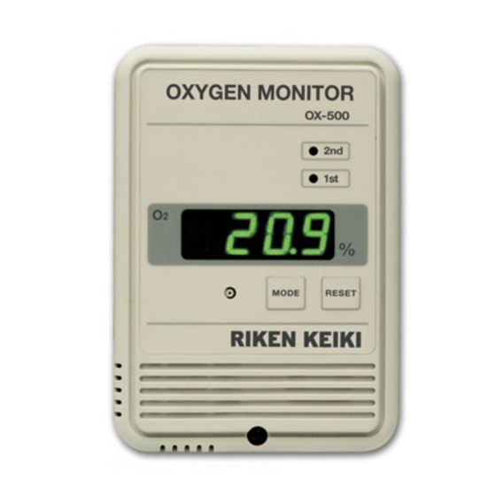
Manual Supplement
OX-500
The following procedure assumes the use of a calibration kit which includes a
100% nitrogen calibration gas cylinder, a zero air cylinder, a 2.0 LPM fixed flow
regulator with an on/off knob, a calibration cup, and a short piece of sample
tubing to connect the regulator to the calibration cup.
The following procedure assumes that the OX-500 is not in a fresh air
environment. If a fresh air environment can be verified, applying zero air to the
detector is not necessary when setting the span adjustment.
reading.
2 - 1
the MODE Switch. It is labelled on page 5 of the attached OX-500 manual. A tool
such as a small tipped screwdriver or a pencil may be used to press the MAINTE
Switch.
P. 1 of 3
Released: 1/25/13
www.rkiinstruments.com
Advertisement
Table of Contents

Subscribe to Our Youtube Channel
Related Manuals for RKI Instruments OX-500


Summary of Contents for RKI Instruments OX-500
- Page 1 NOTE: The MAINTE Switch is a small recessed push button switch located to the left of the MODE Switch. It is labelled on page 5 of the attached OX-500 manual. A tool such as a small tipped screwdriver or a pencil may be used to press the MAINTE Switch.
- Page 2 0.0 %. If the zero adjustment is not successful, the LCD will indicate the error message Err. 10. Remove the calibration cup from the front face of the OX-500. 11. Turn the regulator knob clockwise to close the regulator.
- Page 3 Manual Supplement OX-500 Spare Parts List Table 1 below lists spare parts for the OX-500. Table 1: Spare Parts List Part Number Description 06-1248RK-03 Calibration tubing, 3/16” ID x 5/16” OD, 3 foot length 81-OX500-LV Calibration kit, 2 LPM regulator, 100% nitrogen, 34 liter...
Need help?
Do you have a question about the OX-500 and is the answer not in the manual?
Questions and answers