Table of Contents
Advertisement
Quick Links
Advertisement
Table of Contents

Subscribe to Our Youtube Channel
Related Manuals for wtw IQ Sensor Net MIQ/24V


Summary of Contents for wtw IQ Sensor Net MIQ/24V
- Page 2 © Copyright Weilheim 2006, WTW GmbH Reprinting - even as excerpts - is only allowed with the explicit written authorization of WTW GmbH, Weilheim. Printed in Germany. ba64114e02 08/2006...
-
Page 3: Table Of Contents
MIQ/24V List of contents MIQ/24V - List of contents Overview ........1-1 How to use this component operating manual . - Page 4 List of contents MIQ/24V 0 - 2 ba64114e02 08/2006...
-
Page 5: Overview
MIQ/24V Overview Overview How to use this component operating manual Structure of the IQ IQ Sensor Net Operating Manual operating ENSOR manual System Operating Manual (Ring Binder) IQ Sensor MIQ Module MIQ Terminal Operating Operating Operating Manual Manual Manual Component Operating Manuals Fig. -
Page 6: Features Of The Miq/24V
Overview MIQ/24V Features of the MIQ/24V General characteristics The MIQ/24V power supply supplies the IQ S with its oper- ENSOR ational voltage. The operational voltage is forwarded to the consumers in the following ways: z In the case of stacked mounting, via the IQ S contacts on ENSOR the front and rear of the module... -
Page 7: Safety Instructions
MIQ/24V Safety instructions Safety instructions This component operating manual contains special instructions that must be followed during the installation of the MIQ/24V power supply module. Thus, it is essential to read this component operating manual before carrying out any work with the system. In addition to this manual, the S chapter of the IQ S system operating manual... -
Page 8: Authorized Use
Safety instructions MIQ/24V Authorized use The authorized use of the MIQ/24V consists of its use as a power supply module in the IQ S ENSOR The technical specifications given in chapter 5 T must ECHNICAL DATA be observed. Only operation according to the instructions in this component operating manual is authorized. -
Page 9: Installation
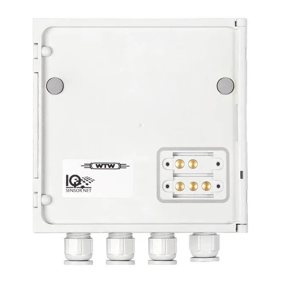
MIQ/24V Installation Installation Scope of delivery The scope of delivery of the MIQ/24V is listed in the I NSTALLATION chapter of the system operating manual. Installation in the IQ S ENSOR The IQ S provides a number of options for integrating the ENSOR MIQ/24V mechanically and electrically in the system (stacked mounting, distributed mounting, etc.). - Page 10 Installation MIQ/24V Note Battery systems should be protected against total discharge. The MIQ/24V does not have an integrated protection against total dis- charge. General installation Follow these instructions when connecting the connecting wires to the instructions terminal strip: z Shorten all the wires to be used to the length required for the instal- lation z Always fit all the ends of the wires with wire end sleeves before con- necting them to the terminal strip...
- Page 11 MIQ/24V Installation Connecting the the Open the module. 24 V AC/DC line X11 X10 24 V AC/DC T 1,6 A POWER INPUT SENSORNET 3 SENSORNET 2 SENSORNET 1 Fig. 3-2 Connecting the 24 V AC/DC cable. Screw the cable gland (pos. 1 in Fig. 3-2) with the sealing ring (pos.
- Page 12 Installation MIQ/24V Warning No free wires must be allowed to project into the housing. Other- wise, there is a danger of electric short circuit that may cause fire. Always cut off any wires that are not in use as closely as possible to the cable gland.
-
Page 13: Maintenance And Cleaning
MIQ/24V Maintenance and cleaning Maintenance and cleaning Maintenance The MIQ/24V requires no special maintenance. The general mainte- nance of IQ S components is described in the IQ S ENSOR ENSOR system operating manual. Cleaning The cleaning of IQ S components is described in the IQ ENSOR system operating manual. - Page 14 Maintenance and cleaning MIQ/24V 4 - 2 ba64114e02 08/2006...
-
Page 15: Technical Data
MIQ/24V Technical data Technical data Note General technical data on MIQ modules are given in the T ECHNICAL chapter of the IQ S system operating manual. DATA ENSOR Electrical data Power supply Nominal voltage: 24 V AC/DC - 15 % / + 20 % Safety Extra Low Voltage (SELV) AC Frequency:... - Page 16 Technical data MIQ/24V Number of MIQ/24V in Maximum of 3, depending on the overall an IQ S sys- power requirement of the system (see sys- ENSOR tem operating manual, section P RINCIPLES OF AN OPTIMUM INSTALLATION Instrument internal 5 x 20 T 1.6 A, with UL approval fuses Manufacturer: Littlefuse...
- Page 18 Wissenschaftlich-Technische Werkstätten GmbH Dr.-Karl-Slevogt-Straße 1 D-82362 Weilheim Germany Tel: +49 (0) 881 183-0 +49 (0) 881 183-100 Fax: +49 (0) 881 183-420 E-Mail: Info@WTW.com Internet: http://www.WTW.com...
Need help?
Do you have a question about the IQ Sensor Net MIQ/24V and is the answer not in the manual?
Questions and answers