Table of Contents
Advertisement
Quick Links
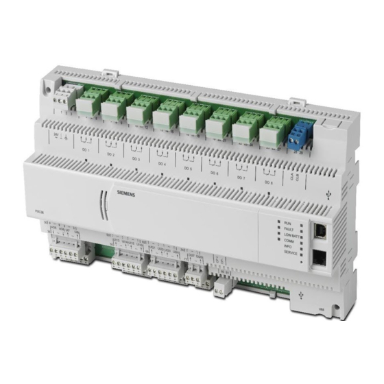
PXC Compact 36
Danger/Warning/Caution Notations
DANGER
Electric shock, death, or severe
property damage may occur if you do
not perform a procedure as specified.
WARNING:
Personal injury or property damage
may occur if you do not follow a
procedure as specified.
CAUTION:
Equipment damage or loss of data
may occur if you do not follow a
procedure as specified.
Product Numbers
PXC36-E.A
PXC Compact, 36 point, BACnet/IP or MS/TP
ALN
PXC36-EF.A
PXC Compact, 36 point, BACnet/IP or MS/TP
ALN, Island Bus, P1 or MS/TP FLN
PXC Compact, 36 point, Ethernet/IP or RS-485
PXC36-PE.A
ALN
PXC36-PEF.A PXC Compact, 36 point, Ethernet/IP or RS-485
ALN, Island Bus, P1 FLN
For more information, see the
Instructions
(553-141) and
Bus Modules Installation Instructions
Product Description
The PXC Compact Series communicates with other field
panels or workstations on a peer-to-peer Automation
Level Network (ALN), or on the Field Level Network
(FLN), and supports the following communication
options:
•
BACnet/IP or Ethernet TCP/IP over 10/100 MB
Ethernet networks
•
RS-485 P2 or BACnet MS/TP on RS-485
networks
Required Tools and Materials
•
Wire stripper/side cutter
•
Small flat-blade screwdriver
•
Phillips screwdriver
•
Electric drill and Phillips driver bit
•
Level
•
Tape measure
•
Digital multimeter (DMM)
Siemens Industry Inc.
Item Number: 553-504(CA)
TX-I/O Module Installation
TX-I/O Power Supply and
(553-142).
•
Black marker
•
Masonry drill bit (to mount on concrete or
masonry)
•
Four wall anchors (to mount on concrete or
masonry)
•
Optional DIN rail (1.38" × 0.3" × 0.04" (35 mm ×
7.5 mm × 1 mm))
Included Materials
The following screws are included for mounting the PXC
Compact without a DIN rail:
•
Four No. 8-18 × 3/8" self-tapping Phillips screws
•
Four No. 8-18 × 3/4" self-drilling Phillips screws
•
Two No. 8-18 × 1-3/4" self-drilling Phillips screws
Expected Installation Time
20 minutes
Prerequisites
CAUTION:
No power wiring is connected to the field
panel controller or other TX-I/O
components at this time.
The TX-I/O island bus must be mounted on
a DIN rail (1.38" × 0.3" × 0.04" (35 mm ×
7.5 mm × 1 mm)).
•
If mounting in an enclosure:
−
Enclosure is installed, DIN rail included.
−
The power source is installed, as applicable.
−
The power is OFF.
•
All necessary wiring is pulled and terminated per
the layout drawing.
•
Power and communication wiring is terminated to
the removable plugs supplied with the devices.
CE Compliance Requirements
Must be installed inside a metal enclosure rated at IP20
minimum.
Energy Management Applications
For energy management only (low voltage Class 2), the
PXC Compact may be mounted on a flat surface.
Installation Instructions
Document No. 553-504
October 9, 2019
Page 1 of 5
Advertisement
Table of Contents

Subscribe to Our Youtube Channel
Related Manuals for Siemens PXC Compact Series


Summary of Contents for Siemens PXC Compact Series
- Page 1 The TX-I/O island bus must be mounted on a DIN rail (1.38" × 0.3" × 0.04" (35 mm × Product Description 7.5 mm × 1 mm)). The PXC Compact Series communicates with other field • If mounting in an enclosure: panels or workstations on a peer-to-peer Automation Level Network (ALN), or on the Field Level Network −...
- Page 2 TX-I/O Power Supplies. More power may be required if using a Modular Series with the maximum number of TX-I/O modules. Figure 1: Example ALN Configuration for Smoke Control. Page 2 of 5 Siemens Industry, Inc.
- Page 3 Allow a minimum clearance of 3 inches (7.6 If you need to reinsert one of the mounting cm) around the field panel ports and tabs, see the PXC Compact Series Owner’s connectors for terminating wires. Manual (553-104) for instructions. Select one of the following options for fastening the...
- Page 4 Guidelines for Field Panels and Equipment Controllers Terminate power wiring to the 24 Vac removable (125-3002). plug. The installation is now complete. If required, remove the RS-485 plug and terminate the communication wiring. Siemens Industry Inc. Page 4 of 5...
- Page 5 Siemens Schweiz AG. Other product or company names mentioned herein may be the trademarks of their respective owners. © 2019 Siemens Industry, Inc. All presented offerings are subject to a cyber security disclaimer which is available at: www.siemens.com/bt/cyber-security.
Need help?
Do you have a question about the PXC Compact Series and is the answer not in the manual?
Questions and answers