Table of Contents
Advertisement
Quick Links
Manual, Control Module, PROFINET, DL12
Document #9620-20-C-DL12-06
Glossary ........................................................................................................................................C-3
C. Control and Signal Modules ...................................................................................................C-5
®
1.
Product Overview ..................................................................................................................C-5
1.1
Master Module ........................................................................................................................... C-5
1.2
Tool Module ............................................................................................................................... C-6
2.
Product Information ..............................................................................................................C-7
2.1
Master Module .......................................................................................................................... C-7
2.1.1
PROFINET Interface Information ................................................................................... C-7
2.1.2
Integrated Ethernet Switch ............................................................................................. C-7
2.1.3
System Failure and Bus Failure LEDs ......................................................................... C-13
2.1.4
Ethernet 1 and Ethernet 2 LEDs .................................................................................. C-14
2.1.5
Reset To Factory Push Button ...................................................................................... C-15
2.2
Arc Prevention Circuit ............................................................................................................ C-15
2.2.1
Arc Prevention Circuit Behavior during Coupling ......................................................... C-15
2.2.2
Arc Prevention Circuit Behavior during Uncoupling ..................................................... C-16
2.3
Tool Module ............................................................................................................................ C-17
2.4
Safety System .......................................................................................................................... C-18
3.
Installation ...........................................................................................................................C-20
3.1
Master Module Installation ..................................................................................................... C-20
3.2
Master Module Removal ......................................................................................................... C-21
3.3
Tool Module Installation ......................................................................................................... C-21
3.4
Tool Module Removal ............................................................................................................. C-22
3.5
PROFINET Interface ................................................................................................................ C-22
3.6
Utility Schematic ..................................................................................................................... C-22
3.7
Electrical Connections ............................................................................................................ C-22
3.8
Setting the Tool-ID ................................................................................................................... C-23
4.
Operation .............................................................................................................................C-24
4.1
Lock, Unlock, and RTL Sensor Cable LED Behavior ........................................................... C-24
4.2
Inputs ........................................................................................................................................ C-25
4.2.1
EVERYTHING IS OK.................................................................................................... C-25
4.2.2
Locked .......................................................................................................................... C-25
4.2.3
Latch Enabled .............................................................................................................. C-25
4.2.4
RTL1 and RTL2 ............................................................................................................ C-25
4.2.5
SSO 1 and SSO 2 ........................................................................................................ C-25
4.2.6
SS Pulse Missing ......................................................................................................... C-25
Pinnacle Park • 1031 Goodworth Drive • Apex, NC 27539 • Tel: 919.772.0115 • Fax: 919.772.8259 •
Table of Contents
C-1
www.ati-ia.com
Advertisement
Table of Contents

Related Manuals for ATI Technologies PROFINET DL12


Summary of Contents for ATI Technologies PROFINET DL12
-
Page 1: Table Of Contents
Manual, Control Module, PROFINET, DL12 Document #9620-20-C-DL12-06 Table of Contents Glossary ............................C-3 C. Control and Signal Modules ....................C-5 ® DL12—PROFINET Control/Signal Module ................C-5 Product Overview ........................C-5 Master Module ........................... C-5 Tool Module ..........................C-6 Product Information ......................C-7 Master Module .......................... C-7 2.1.1 PROFINET Interface Information ................... - Page 2 Manual, Control Module, PROFINET, DL12 Document #9620-20-C-DL12-06 4.2.7 Tool Power Is On ......................C-25 4.2.8 Tool Present ......................... C-25 4.2.9 Unlatch Enabled ......................C-26 4.2.10 Unlocked ........................C-26 4.2.11 US1 Power Present ...................... C-26 4.2.12 US2 Power Present ...................... C-26 4.2.13 V1 Relay and V2 Relay ....................
-
Page 3: Glossary
Manual, Control Module, PROFINET, DL12 Document #9620-20-C-DL12-06 Glossary Definition Term A board inside the module which controls solenoid outputs, monitors function of the unlatch valves for pressure and position, safety checking Application Processor 1 and diagnostics, reports sensor status, protects outputs against short circuit overload, detects and reports status of the 24 V power supply, and provides cross monitoring of the pressure processor board. - Page 4 Manual, Control Module, PROFINET, DL12 Document #9620-20-C-DL12-06 Definition Term An input indicating the presence of Output Power (US2) at the ATI Master US2 Power Present module. The “Tool Power is ON” bit is set high when the Arc Prevention Circuit has Tool Power is On activated power on the Tool side.
-
Page 5: Control And Signal Modules
Manual, Control Module, PROFINET, DL12 Document #9620-20-C-DL12-06 C. Control and Signal Modules DL12—PROFINET Control/Signal Module ® 1. Product Overview The modules enable the customer to control and communicate with the Tool Changer through a network using a PROFINET interface. A PROFINET node is established on the Master module, but not on the Tool. Control of the Tool Changer is realized through the Master node along with the reporting of various Tool Changer I/O. -
Page 6: Tool Module
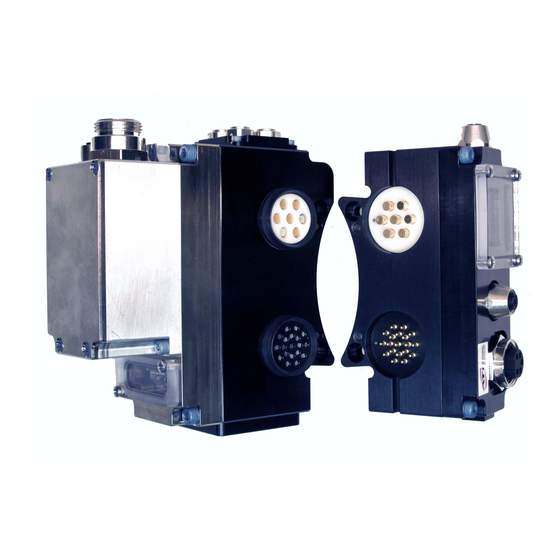
Manual, Control Module, PROFINET, DL12 Document #9620-20-C-DL12-06 Figure 1.1—Modules DL12 Master Module 4-Pin Female D-coded PROFINET Connector SF, Ethernet 2, BF, 5-Pin Male Minifast Ethernet 1 LED's, Power Connector and Reset Switch FE Ground Terminal Connection (4) 3-Pin Female M8 RTL, Lock, and Unlock Connector 19-Pin Spring Signal Contact and Rubber V-ring Seal... -
Page 7: Product Information
Manual, Control Module, PROFINET, DL12 Document #9620-20-C-DL12-06 2. Product Information A PROFINET node is established on the Master module but not on the Tool. Control of the Tool Changer is realized through the Master node along with the reporting of various Tool Changer I/O. The Tool module supports Tool‑ID reported through the Master and functions as a pass‑through for PROFINET network and power to downstream equipment. - Page 8 Manual, Control Module, PROFINET, DL12 Document #9620-20-C-DL12-06 Table 2.2—I/O Bit map, Robot Inputs from 9121-DL12-M Byte Bit# Name Description/Function Locked Tool Changer is locked Unlocked Tool Changer is unlocked Latch Enabled Tool Changer is ready to Latch Unlatch Enabled Tool Changer is ready to Unlatch RTL1 Ready to Lock Prox1 I/P RTL2...
- Page 9 Manual, Control Module, PROFINET, DL12 Document #9620-20-C-DL12-06 Table 2.2—I/O Bit map, Robot Inputs from 9121-DL12-M Byte Bit# Name Description/Function Valve or pressure sensor defect. Logical OR of APx_VALVE_ VALVE_ERROR ERROR bits. CROSS_ Safety System detected mismatch. Logical OR of the APx_ MONITORING_ INP_MISMATCH, APx_OUTP_MISMATCH, and AP2_COMM_ ERROR...
- Page 10 Manual, Control Module, PROFINET, DL12 Document #9620-20-C-DL12-06 Table 2.2—I/O Bit map, Robot Inputs from 9121-DL12-M Byte Bit# Name Description/Function Raw Locked Sensor Direct mirror of locked proximity sensor. Raw Unlocked Direct mirror of unlocked proximity sensor. Sensor Valve Proximity Shows status of valve position. Sensor AP2_Comm_Error AP1 lost communication to AP2...
- Page 11 Manual, Control Module, PROFINET, DL12 Document #9620-20-C-DL12-06 Table 2.2—I/O Bit map, Robot Inputs from 9121-DL12-M Byte Bit# Name Description/Function AP2_SSO_2 V1Relay V2Relay AP2_SSFAULT Unlatch_Valve_ Control_2 Valve_Position AP2_Version_Error AP2_Safety_Error Pressure Reading Bit 8 Pressure Reading Bit 9 Unused Pressure Reading Bit 0 Pressure Reading Bit 1 Pressure Reading...
- Page 12 Manual, Control Module, PROFINET, DL12 Document #9620-20-C-DL12-06 Table 2.2—I/O Bit map, Robot Inputs from 9121-DL12-M Byte Bit# Name Description/Function Unused Unused Major Version Number of AP2 [0:4] AP2 Firmware Revision Number Minor Version Number of AP2 [0:4] 0 to 7 Reserved Notes: These bits should be mapped for customer use.
-
Page 13: System Failure And Bus Failure Leds
Manual, Control Module, PROFINET, DL12 Document #9620-20-C-DL12-06 2.1.3 System Failure and Bus Failure LEDs When the modules are coupled and communicating properly on the network, the LEDs should When the modules are coupled and communicating properly on the network, the LEDs should display as shown in Figure 2.1, with the E1 and E2 LEDs RED (solid) and Green (solid) based on... -
Page 14: Ethernet 1 And Ethernet 2 Leds
Manual, Control Module, PROFINET, DL12 Document #9620-20-C-DL12-06 2.1.4 Ethernet 1 and Ethernet 2 LEDs The Ethernet LEDs provide information about link status and activity on the ports of the integrated Ethernet switch. The Ethernet 1 (E1) LED will display the status of the robot side Ethernet port. The Ethernet 2 (E2) LED will display the status of the Tool side Ethernet port. -
Page 15: Reset To Factory Push Button
Manual, Control Module, PROFINET, DL12 Document #9620-20-C-DL12-06 2.1.5 Reset To Factory Push Button A push button, located under the LED window cover between the E2 and BF LED allows the user to perform a “Reset To Factory” function which clears the PROFINET Name Of Station and the module’s IP address. -
Page 16: Arc Prevention Circuit Behavior During Uncoupling
Manual, Control Module, PROFINET, DL12 Document #9620-20-C-DL12-06 2.2.2 Arc Prevention Circuit Behavior during Uncoupling The behavior of the Arc Prevention Circuit during uncoupling can be more clearly understood by referring to Figure 2.4, which shows the power‑off timing diagram for the Arc Prevention Circuit. Starting at the top of the diagram, the UNLATCH command is issued thus initiating uncoupling of the Master and Tool. -
Page 17: Tool Module
Manual, Control Module, PROFINET, DL12 Document #9620-20-C-DL12-06 2.3 Tool Module The Tool module utilizes a rapid communication method to report the Tool‑ID information from the push button switches to the Master module as soon as the Tool Changer or Utility Coupler is coupled. Typically the Tool‑ID information is available to the Master within 150 ms from the time the Tool Changer or Utility Coupler is coupled. -
Page 18: Safety System
Manual, Control Module, PROFINET, DL12 Document #9620-20-C-DL12-06 2.4 Safety System The safety system is designed to avoid unintentional Tool release, by integrating a non‑contact safety switch, (2) pneumatically interconnected solenoid valves, dual relays, and (2) cross monitoring processors into the safety circuit. - Page 19 Manual, Control Module, PROFINET, DL12 Document #9620-20-C-DL12-06 The safety switch (not included with module) is mounted on Tool side of the module. The actuator is mounted to the tool stand. The safety switch is connected to the Tool module by a five conductor M12 cable. Refer to the dual double solenoid valve adapter manual (9620‑20‑C‑Jxx Valve Adapters with Dual Double Solenoid, Valve Pass Through, Proximity and Pressure Sensors) for detailed information on the dual double solenoid valve functionality.
-
Page 20: Installation
Manual, Control Module, PROFINET, DL12 Document #9620-20-C-DL12-06 3. Installation The modules are typically installed by ATI prior to shipment. The steps below outline the field installation or removal as required. For wiring information refer to Section 9—Drawings. WARNING: Do not perform maintenance or repair(s) on the Tool Changer or modules unless the Tool is safely supported or placed in the tool stand, all energized circuits (e.g. -
Page 21: Master Module Removal
Manual, Control Module, PROFINET, DL12 Document #9620-20-C-DL12-06 Figure 3.1 —Master Module Installation Use Ledge Mounting Feature Valve Adapter (9121-JR4-M Shown) to Properly Align Module S2 Connector S1 Connector (2) M6 Socket Head Cap Screw Valve Adapter Pressure (S1) and Proximity (S2) Sensors are not shown. -
Page 22: Tool Module Removal
Manual, Control Module, PROFINET, DL12 Document #9620-20-C-DL12-06 8. Connect the 5‑pin power cable and PROFINET cable connectors to the module. 9. Remove the 5 mm set screw from the FE ground terminal using a 3 mm hex key. 10. Connect the ground to the FE grounding terminal using a M5 customer supplied fastener. 11. -
Page 23: Setting The Tool-Id
Manual, Control Module, PROFINET, DL12 Document #9620-20-C-DL12-06 3.8 Setting the Tool-ID There are (5) push button switches are provided on the Tool module for setting of a Tool‑ID number. Each Tool must have an unique 5 digit Tool‑ID number. Tools required: Phillips screw driver Figure 3.3—Setting the Tool-ID Decrease (-) Digit Set Tool-ID to an... -
Page 24: Operation
Manual, Control Module, PROFINET, DL12 Document #9620-20-C-DL12-06 4. Operation A thorough understanding of the advanced diagnostic and fault reporting capability is required to proficiently operate this product. The following information is provided to help define the behavior of the Master/ Tool modules. -
Page 25: Inputs
Manual, Control Module, PROFINET, DL12 Document #9620-20-C-DL12-06 4.2 Inputs The following describes the most critical inputs from the ATI Master module. 4.2.1 EVERYTHING IS OK This is an overall status bit that indicates if there is an error condition that will block an unlatch request. -
Page 26: Unlatch Enabled
Manual, Control Module, PROFINET, DL12 Document #9620-20-C-DL12-06 4.2.9 Unlatch Enabled The Unlatch Enabled bit indicates when the preconditions for unlatching the Tool Changer have been met. The preconditions include: • No Errors • US1 and US2 Power within operating range •... -
Page 27: Error On Unlatch1
Manual, Control Module, PROFINET, DL12 Document #9620-20-C-DL12-06 4.3.4 ERROR ON UNLATCH1 This bit indicates that a short circuit or overload condition on the UNLATCH output to Valve 1 has been detected. The error condition can be reset with the Clear Errors bit. 4.3.5 ERROR ON UNLATCH2 This bit indicates that a short circuit or overload condition on the UNLATCH output to Valve 2 has been detected. -
Page 28: Unsafe Unlatch
Manual, Control Module, PROFINET, DL12 Document #9620-20-C-DL12-06 4.3.13 UNSAFE UNLATCH An UNLATCH command shall only be performed if the following conditions are met: • SSO1, SSO2, V1RELAY, and V2RELAY must be ON indicating that the Tool Changer is nested safely in the Tool Stand. Everything is OK bit must be ON indicating no errors. -
Page 29: Error Recovery Sequence
Manual, Control Module, PROFINET, DL12 Document #9620-20-C-DL12-06 Table 4.2—Error Conditions TRIGGERS Error Bit Error Description SYSTEM_IS_ Reset with UNSAFE ERROR Communication failure between AP2_COMM_ERROR Clear Errors Bit Application Processor 1 and 2 CROSS_MONITORING_ Application Processor safety related Clear Errors Bit ERROR inputs and outputs do not match Short circuit detection on LATCH... -
Page 30: Recommended Sequence Of Operation
Manual, Control Module, PROFINET, DL12 Document #9620-20-C-DL12-06 4.4 Recommended Sequence of Operation Before programing can take place, the following condition must be met: • Input and Output Auxiliary 24 VDC power is available and within acceptable range (20.4 - 28.8 VDC). •... - Page 31 Manual, Control Module, PROFINET, DL12 Document #9620-20-C-DL12-06 Figure 4.3—Master Moves into Tool and is parallel within 0.06” to 0.15” Unlock (U) RTL (R1) SF LED is Green E2 LED is Red/Green Then Red Flashing/Green Then Off BF LED is Off E1 LED is Red/Green RTL (R2) Lock (L)
- Page 32 Manual, Control Module, PROFINET, DL12 Document #9620-20-C-DL12-06 Figure 4.5—Master Coupled with Tool RTL (R1) Unlock (U) SF LED is Green E2 LED is Red/Green BF LED is Off E1 LED is Red/Green RTL (R2) Lock (L) Green LED (Power) Yellow LED (Switch Made) NOTICE: If the LEDs don’t match what is shown, refer to Section 2.1.3—System Failure and...
- Page 33 Manual, Control Module, PROFINET, DL12 Document #9620-20-C-DL12-06 Figure 4.6—Master Coupled with Tool Moves Out of the Stand RTL (R1) Unlock (U) SF LED is Green E2 LED is Red/Green BF LED is Off E1 LED is Red/Green RTL (R2) Lock (L) Green LED (Power) Yellow LED (Switch Made)
- Page 34 Manual, Control Module, PROFINET, DL12 Document #9620-20-C-DL12-06 Figure 4.7—Master Coupled with Tool Returned to Stand RTL (R1) Unlock (U) SF LED is Green E2 LED is Red/Green BF LED is Off E1 LED is Red/Green RTL (R2) Lock (L) Green LED (Power) Yellow LED (Switch Made) NOTICE: If the LEDs don’t match what is shown, refer to...
- Page 35 Manual, Control Module, PROFINET, DL12 Document #9620-20-C-DL12-06 Figure 4.8—Master Uncoupled, Moves away from Tool and is parallel within 0.06” to 0.15” Unlock (U) RTL (R1) SF LED is Green E2 LED is Red/Green Then Red Flashing/Green Then Off BF LED is Off E1 LED is Red/Green RTL (R2) Lock (L)
-
Page 36: Maintenance
Manual, Control Module, PROFINET, DL12 Document #9620-20-C-DL12-06 5. Maintenance The modules are not designed to be field serviced as all point‑to‑point wiring connections are soldered. Component replacement is limited to the V‑ring seal on the Master. WARNING: Do not perform maintenance or repair(s) on the Tool Changer or modules unless the Tool is safely supported or placed in the tool stand, all energized circuits (e.g. -
Page 37: Pin Block Inspection And Cleaning
Manual, Control Module, PROFINET, DL12 Document #9620-20-C-DL12-06 5.1 Pin Block Inspection and Cleaning Tools required: Nylon Brush (ATI Part Number 3690‑0000064‑60) 1. Place the Tool in a secure location. 2. Uncouple the Master and Tool plates. 3. Turn off and de‑energize all energized circuits (e.g. electrical, air, water, etc.). 4. -
Page 38: Troubleshooting And Service Procedures
Manual, Control Module, PROFINET, DL12 Document #9620-20-C-DL12-06 6. Troubleshooting and Service Procedures Troubleshooting information and service procedures are covered in the following section to help diagnose and resolve conditions with the Tool Changer or Utility Coupler. WARNING: Do not perform maintenance or repair(s) on the Tool Changer or modules unless the Tool is safely supported or placed in the tool stand, all energized circuits (e.g. -
Page 39: Service Procedures
Manual, Control Module, PROFINET, DL12 Document #9620-20-C-DL12-06 Table 6.1—Troubleshooting Symptom Possible Cause Correction Latch command not Verify that the Latch command has been issued. issued. No power on the Tool side. Tool Power is On bit. Verify that the Tool Power is On bit is HIGH. Tool Present bit. -
Page 40: Dl12 Device Replacement Procedures
Manual, Control Module, PROFINET, DL12 Document #9620-20-C-DL12-06 6.2.2 DL12 Device Replacement Procedures The device replacement procedures are based on the following assumptions: • The topology of the PROFINET network was properly defined with the PROFINET engineering tool. • The PROFINET controller supports automatic device replacement. 6.2.2.1 DL12 Master Module Replacement Procedures 1. - Page 41 Manual, Control Module, PROFINET, DL12 Document #9620-20-C-DL12-06 8. Loosen the (2) M3 pan head captive screws and remove LED window. 9. Locate reset button between BF and E2 LED. 10. Use a non‑conductive tool (e.g. plastic stylus) to press on the reset button ‑> the SF LED will change from GREEN to blinking RED, indicating that the module will clear its name and IP address after the next power cycle.
-
Page 42: Serviceable Parts
Manual, Control Module, PROFINET, DL12 Document #9620-20-C-DL12-06 7. Serviceable Parts Refer to Section 9—Drawings 7.1 Master Module Mounting Fasteners Table 7.1—Master Module Mounting Fasteners Part Number Description M6 x 20 Socket Head Cap Screw, SS, ND Microspheres, 0-3 3500-1066020-21A uncoated lead thds. 5-7 coated thds. IFI525 7.2 Tool Module Mounting Fasteners Table 7.2—Tool Module Mounting Fasteners Part Number... -
Page 43: Specifications
Manual, Control Module, PROFINET, DL12 Document #9620-20-C-DL12-06 8. Specifications Table 8.1—Master Specifications Profinet Master module with integrated Ethernet switch. D‑Coded 4‑Pin M12 connector for Profinet communication, 5‑pole Mini Connector for Switched and Unswitched 9121-DL12-M Auxiliary power. Arc Prevention applied to Switched and Unswitched Auxiliary power. Lock, Unlock, and RTL sensing with LED cables on the Master. - Page 44 Manual, Control Module, PROFINET, DL12 Document #9620-20-C-DL12-06 Table 8.2—Tool Specifications Profinet Tool module. D‑Coded 4‑Pin M12 Connector for Profinet, 5‑pole Mini 9121-DL12-T Connector for Auxiliary power. Supports Arc Prevention. 5-Pin M12 to support TSI on the Tool and 5-Independent Switch Tool-ID. Mates with DL12 Master. Default Configuration (5) Independent Tool-ID switches, each reading a (0–9) position (all factory set to Tool for Tool-ID...
-
Page 45: Drawings
Manual, Control Module, PROFINET, DL12 Document #9620-20-C-DL12-06 9. Drawings Pinnacle Park • 1031 Goodworth Drive • Apex, NC 27539 • Tel: 919.772.0115 • Fax: 919.772.8259 • www.ati-ia.com C-45... - Page 46 Manual, Control Module, PROFINET, DL12 Document #9620-20-C-DL12-06 Pinnacle Park • 1031 Goodworth Drive • Apex, NC 27539 • Tel: 919.772.0115 • Fax: 919.772.8259 • www.ati-ia.com C-46...
- Page 47 Manual, Control Module, PROFINET, DL12 Document #9620-20-C-DL12-06 Pinnacle Park • 1031 Goodworth Drive • Apex, NC 27539 • Tel: 919.772.0115 • Fax: 919.772.8259 • www.ati-ia.com C-47...
- Page 48 Manual, Control Module, PROFINET, DL12 Document #9620-20-C-DL12-06 Pinnacle Park • 1031 Goodworth Drive • Apex, NC 27539 • Tel: 919.772.0115 • Fax: 919.772.8259 • www.ati-ia.com C-48...
- Page 49 Manual, Control Module, PROFINET, DL12 Document #9620-20-C-DL12-06 Pinnacle Park • 1031 Goodworth Drive • Apex, NC 27539 • Tel: 919.772.0115 • Fax: 919.772.8259 • www.ati-ia.com C-49...
- Page 50 Manual, Control Module, PROFINET, DL12 Document #9620-20-C-DL12-06 Pinnacle Park • 1031 Goodworth Drive • Apex, NC 27539 • Tel: 919.772.0115 • Fax: 919.772.8259 • www.ati-ia.com C-50...
Need help?
Do you have a question about the PROFINET DL12 and is the answer not in the manual?
Questions and answers