Advertisement
Available languages
Available languages
Quick Links
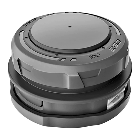
REPLACEMENT STRING TRIMMER HEAD
This replacement string trimmer head is exclusively compatible with
EGO multi-tool string trimmer attachment STA1500 /STA1500-FC and EGO rear motor
string trimmer ST1530/ST1530-FC.
DANGER:
If the head loosens after it is fixed in position, replace it immediately. Never use a trimmer
with a loose cutting attachment. Replace a cracked, damaged or worn out cutting head immediately, even
if damage is limited to superficial cracks. Such attachments may shatter at high speed and cause serious
injury.
WARNING:
Always remove the battery pack from the product when you are assembling parts,
making adjustments, cleaning, or when the product is not in use.
1
Flange
Flange Cover
Spool
Slot in the Flange
Upper Cover
Nut
Spring
REMOVE THE TRIMMER HEAD
1. Remove the battery pack.
2. Hold the trimmer head as shown in Fig. 2
and use one thumb to press one release tab
2
on either side while gently pulling on the
lower cover assembly with the other hand to
release the tab.
3. Repeat on the other side to release the other
release tab from the trimmer head.
4. Remove the lower cover assembly with the
spring from the trimmer head (Fig. 3).
Release Tab
5. Remove the cutting line from the spool
(Fig. 4).
3
4
Spring
Lower Cover Assembly
6. Rotate the spool to align the slot in the flange with the hole in the gear case (Fig. 5).
7. Insert a suitable hex wrench into the aligned holes to act as a stabilizer (Fig. 6). Wear gloves to hold
the gear case together with the hex wrench, with one hand, and with the other hand, use an impact
socket wrench (3/5", 15mm) to loosen the nut in the clockwise direction (Fig. 7).
8. Remove the nut, spool, and upper cover, in that order. Save the flange on the drive shaft for
reassembly (Fig. 8).
5
OPERATING MANUAL
MODEL NUMBER AH1531
7
Trimmer Line
INSTALL THE NEW TRIMMER HEAD
1. Before installing the new trimmer head, make sure that the flange is located on the drive shaft with
the bulge facing away from the base (Fig. 9) and the flange cover is against the flange, with its flat
surface facing outwards (Fig. 10).
9
Lower Cover Assembly
Bulge facing away from the base
2. Mount the upper cover onto the flange cover
first, and then mount the spool onto the drive
shaft. Before mounting the locking nut, make
sure that when the spool is manually rotated,
the drive shaft rotates, also (see Fig. 8).
3. Pre-tighten the locking nut manually.
4. Rotate the spool to align the slot in the flange
with the hole in the gear case and insert the
hex wrench into the aligned holes to act as a
stabilizer (see Fig. 5 & 6).
5. Wear gloves to hold the gear case together with the hex wrench, with one hand, and with the
other hand, use an impact socket wrench (3/5", 15mm) to tighten the nut in the counterclockwise
direction (Fig. 11).
6. Mount the lower cover assembly with the spring located inside (see Fig. 4).
Stabilizer
6
Aligned Shaft-locking Holes
Spool
8
Wrench(3/5", 15mm)
10
Flat surface facing outwards
11
Wrench(3/5", 15mm)
7. With one hand holding the upper cover, use the other hand to grasp the lower cover assembly and
align the release tabs on the upper cover with the holes in the lower cover assembly; use your palm
to press and slightly rotate the lower cover assembly left and right until the tabs securely lock with
it on both sides (Fig. 12 & 13).
12
Alignment
8. Refer to below "LINE REPLACEMENT" section to wind the cutting line into the trimmer head.
LINE REPLACEMENT
Nut
NOTICE:
Always use the recommended nylon cutting line with a diameter that does not exceed 0.095 in.
Spool
(2.4 mm). Using line other than that specified may cause the string trimmer to overheat or become
damaged.
Upper Cover
WARNING:
Never use metal-reinforced line, wire, or rope, etc. These can break off and become
dangerous projectiles.
Flange Cover
1. Cut one piece of cutting line 16 ft. (5m) long. Insert the line into the eyelet. Push the line until the
Flange
end of the line comes out of the other side of the trimmer head. Pull the line from the other side until
equal amounts of line appear on both sides (Fig. 14).
2. Press, while rotating the lower cover assembly in the direction indicated by the arrow, to wind the
cutting line into the spool that is inside until approximately 5.5in. (14cm) of line is showing on each
side (Fig. 15).
14
Arrow
Direction
Eyelet
3. Push the lower cover assembly down while pulling on the lines to manually advance the line and to
Flange
check for proper assembly of the trimmer head.
13
15
5.5" (14 cm)
Advertisement

Related Manuals for EGO AH1531


Summary of Contents for EGO AH1531
- Page 1 MODEL NUMBER AH1531 This replacement string trimmer head is exclusively compatible with EGO multi-tool string trimmer attachment STA1500 /STA1500-FC and EGO rear motor string trimmer ST1530/ST1530-FC. 8. Refer to below “LINE REPLACEMENT” section to wind the cutting line into the trimmer head.
- Page 2 NUMÉRO DE MODÈLE AH1531 Cette tête de rechange pour taille-bordure est exclusivement compatible avec l’ac- cessoire de taille-bordure multifonction EGO STA1500/STA1500-FC et le taille-bor- dure avec moteur arrière EGO ST1530/ST1530-FC. 8. Consultez la section « REMPLACEMENT DU FIL » ci-dessous pour enrouler le fil de coupe dans la DANGER : Si la tête se desserre après avoir été...
- Page 3 Alignment NÚMERO DE MODELO AH1531 Este cabezal de repuesto para orilladora de hilo es exclusivamente compatible con el accesorio de orilladora de hilo de herramientas múltiples EGO STA1500 /STA1500-FC y la orilladora de hilo con motor posterior EGO ST1530/ST1530-FC. PELIGRO: Si el cabezal se afloja luego de fijarlo en su posición, reemplácelo de inmediato.
Need help?
Do you have a question about the AH1531 and is the answer not in the manual?
Questions and answers
when using the AH1531 it has a different shaft than what came with the original ST1500SF