Advertisement
Quick Links
This bulletin should be used by experienced personnel as a guide to the installation and maintenance of AM-91A,
-92A, 93A; AMAF-91A, -92A, -93A; AMEF-91A, -92A, -93A; FSA-91A, -92A, -93A; VSA-91A, -92A, -93A direct area humidifi ers. Se-
lection or installation of equipment should always be accompanied by competent technical assistance. We encourage you to contact
Armstrong or its local representative if further information is required.
Installation Procedure
Step 1. Check Shipment Against Packing List
All components are listed on the packing
slip. Report any shortages immediately. If
the humidifi er or accessories have been
damaged in transit, notify us and fi le claim
with the transportation company.
Step 2. Mount the Humidifi er
Support it from the ceiling, Fig. 1-3, or bracket
it to a column as shown in Fig. 1-4. There are
holes on both sides of the humidifi er for mounting
purposes.
Exception: Where supply and return connections
for the 91 & 92 size are short, a pipe hanger to
the steam supply line should be suffi cient.
Table 1-1
Model No.
B
AM-91A
15-15/16"
AMAF-91A
15-15/16"
AMEF-91A
15-15/16"
FSA-91A
10-7/8"
VSA-91A
10-7/8"
AM-92A
15-15/16"
AMAF-92A
15-15/16"
AMEF-92A
15-15/16"
FSA-92A
10-7/8"
VSA-92A
10-7/8"
AM-93A
25-1/2"
AMAF-93A
25-1/2"
AMEF-93A
25-1/2"
FSA-93A
20-3/8"
VSA-93A
20-3/8"
Table 1-2
Note: AM models 91, 92 and 93 shown on this bulletin are furnished with
Armstrong C-1801 pneumatic operators. Operator Spring Ranges for
pneumatically controlled humidifi ers.
Armstrong C-1801
Operating Range
5 lbs.
*10 lbs.
*Standard spring — furnished when no spring range is specifi ed.
Installation and Operation
AM-91A, -92A, 93A; AMAF-91A, -92A, -93A; AMEF-91A, -92A, -93A;
FSA-91A, -92A, -93A; VSA-91A, -92A, -93A
Humidifi ers for Direct Area Humidifi cation
C
D
3-3/8"
3-13/16"
3-3/8"
3-13/16"
3-3/8"
3-13/16"
3-3/8"
3-13/16"
3-3/8"
3-13/16"
3-3/8"
3-13/16"
3-3/8"
3-13/16"
3-3/8"
3-13/16"
3-3/8"
3-13/16"
3-3/8"
3-13/16"
4-5/8"
4-3/4"
4-5/8"
4-3/4"
4-5/8"
4-3/4"
4-5/8"
4-3/4"
4-5/8"
4-3/4"
Adjustable Start Points
3 psig min. - 6 psig max.
3 psig min. - 6 psig max.
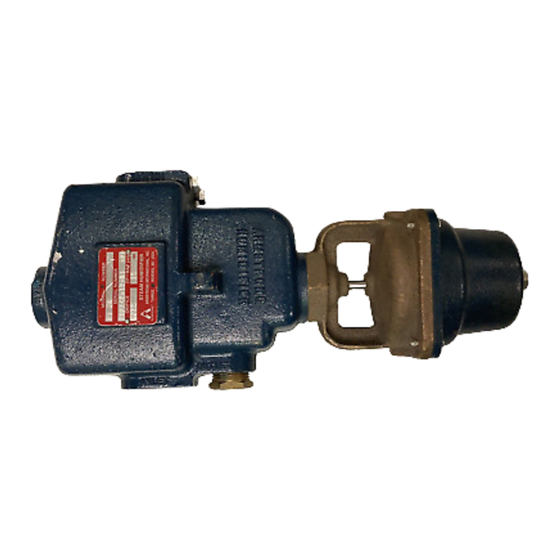
Figure 1-1.
B
E
C
J
D
F
AM, VSA Models
Dimensions, Armstrong Area Humidifi ers. Fig. 1-1 VSA, AM models do not
have fans. Fig. 1-2 FSA, AMEF models have electrically operated fans. AMAF
models utilize air powered fans.
E
F
6-1/16"
3-1/16"
6-1/16"
3-1/16"
6-1/16"
3-1/16"
6-1/16"
3-1/16"
6-1/16"
3-1/16"
6-1/16"
3-13/16"
6-1/16"
3-13/16"
6-1/16"
3-13/16"
6-1/16"
3-13/16"
6-1/16"
3-13/16"
9"
4-3/4"
9"
4-3/4"
9"
4-3/4"
9"
4-3/4"
9"
4-3/4"
Figure 1-3.
Humidifi er suspended from ceiling.
Bulletin 549-A
Figure 1-2.
H
G
E
C
J
D
F
AMEF, AMAF,
FSA Models
G
H
—
—
15-5/8"
14-9/16"
18-9/16"
15-3/4"
17-3/8"
15-3/4"
—
—
—
—
15-5/8"
14-9/16"
18-9/16"
15-3/4"
17-3/8"
15-3/4"
—
—
—
—
—
17-3/4"
21"
18-1/4"
21"
18-1/4"
—
—
Figure 1-4.
Humidifi er bracketed to column.
B
J
13-1/4"
13-1/4"
13-1/4"
13-1/4"
13-1/4"
13-1/4"
13-1/4"
13-1/4"
13-1/4"
13-1/4"
24"
24"
24"
24"
24"
Advertisement

Related Manuals for Armstrong AM-91A


Summary of Contents for Armstrong AM-91A
- Page 1 Humidifi ers for Direct Area Humidifi cation This bulletin should be used by experienced personnel as a guide to the installation and maintenance of AM-91A, -92A, 93A; AMAF-91A, -92A, -93A; AMEF-91A, -92A, -93A; FSA-91A, -92A, -93A; VSA-91A, -92A, -93A direct area humidifi ers. Se- lection or installation of equipment should always be accompanied by competent technical assistance.
-
Page 2: Humidifi Er Piping
Humidifi er Piping Step 3. Run the steam supply line from the steam D. Expansion and Contraction. With average length header to the humidifi er as indicated in Fig. 2-1. Observe of supply line, the dimension change from hot to the following: cold should not exceed 2”. - Page 3 Air and Electrical Connections Step 4. Install the Armstrong Steam Trap and connect Figure 3-1. the trap to the return header. It is important: Pressure Gage To provide a dirt pocket ahead of the trap as Relief shown in the drawings.
- Page 4 Step 7: Install Pneumatic Piping. (AM) turned off. A. Air Supply. Air supply for Armstrong Humidifi ers should be 15 to 20 psi. This air must be clean and dry instrument air. Make air connections to fan of AMAF models.
- Page 5 Your Armstrong Representa- pattern would be practical. Runouts to integral fan units tive can determine air changes for you.
-
Page 6: Operation
Operation utilize a pneumatic humidistat as humidity controller in the space and an How electrically operated units work. After passing through the Armstrong inline air operator to open and close the steam valve. strainer, steam enters the cast iron steam- Explosion hazard humidifi... -
Page 7: Operation And Servicing
Operation and Servicing Putting the Humidifi er Into Operation Humidifi er Discharges Continuously, Even though Humidity Has Reached Desired Level: When Temperature Switch is Employed simply set hu- A. –Mechanical Trouble: midity controller at desired level, and turn on the steam. 1. -
Page 8: Limited Warranty And Remedy
Armstrong’s repair or replacement of the part or product, excluding any labor or any other cost to remove or install said part or product, or at Armstrong’s option, to repayment of the purchase price. As a condition of enforcing any rights or remedies relating to Armstrong products, notice of...