Table of Contents
Advertisement
Quick Links
Advertisement
Table of Contents

Related Manuals for McQuay IM818


Summary of Contents for McQuay IM818
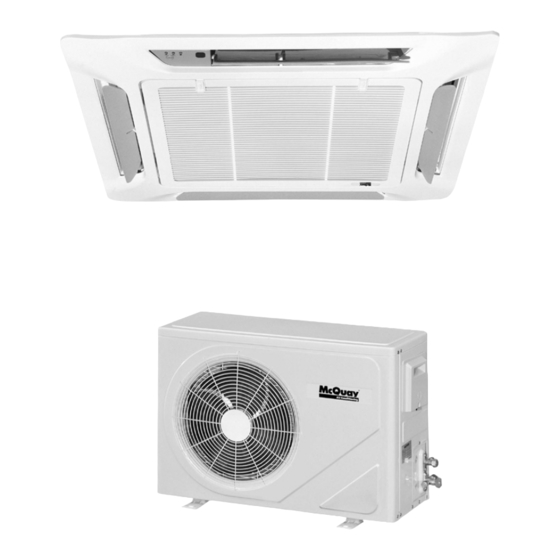
- Page 1 Installation and Maintenance Manual IM818 Group: Unitary Part Number: IM818 Date: March 2005 MCK Ceiling Cassette Ductless Split Type Air Conditioner Indoor Unit Wireless Remote Control (Standard) Wired Wall Outdoor Unit Control (Optional) © 2005 McQuay International IM 818 Page 1...
-
Page 2: Table Of Contents
Table of Contents Model Numbers ......2 Evacuating and Charging....17 Cooling Only . -
Page 3: General Information
General Information This manual provides the installation procedures so your air conditioner unit operates properly and pro- vides you the service it was designed to provide. CAUTION Special adjustment may be necessary to suit local requirements. Before using your air conditioner, Use copper conductors only. -
Page 4: Unit Dimensions
Unit Dimensions Indoor Unit Model: MCK20, 25, 30, 40, 50 A/AR Note: See Figure 3 32 1/4” For More Detail Frame 32 1/4” Front Panel 36 5/8” 14 3/4” 13 3/4” Frame and 36 5/8” Front Panel Outdoor Unit Model: MLC20 & 25B/BR, MLC30, 40 & 50C/CR Electrical Access Panel w/ 7/8”... -
Page 5: Installation Guidelines
Installation Guidelines Installation Diagram Installation of the Indoor Unit Electrical wiring and installation must conform to all national "L" and local codes. 3/4" OD Drain Connection Voltage supply fluctuation must not exceed 10% of rated INDOOR UNIT voltage. Frame Ensure that the location is convenient for wiring, piping and IR Receiver and drainage. -
Page 6: Drain Piping
Water Level Switch Hang the unit on the rods using washers and locknuts. Adjust the unit height to 1" above the finished ceiling surface This normally closed switch will open and turn off the com- and level in all directions (See Figure 4). pressor if the condensate level gets to high. -
Page 7: Air Intake Grille Installation
Plug the 2 electrical cords from the front panel into the 2 Figure 9. Prevent Discharge Air Leakage matching connections inside the control box (See Figure 8). Figure 8. Electrical Connection Front Panel to Control C o o l I n d o o r U n i t A i r Control Box LED Connectors... -
Page 8: Refrigerant Tubing
Refrigerant Tubing Tubing Length & Elevation Table 2: Tube Flaring Dimensions Tube Diameter - OD X (in.) Copper tubing to connect the indoor and outdoor units is sup- plied by others or it can be ordered from the factory. See Inch Imperial Rigid... -
Page 9: Electrical Connections
Electrical Connections Table 4: Wire, Fuse/Breaker Requirements - Cooling Only WARNING Unit Size Voltage - 60Hz. 1 Ph. 208/230 Improper installation can cause severe personal injury Power supply wire size 12 ga. 10 ga. 8 ga. 8 ga. 6 ga. o r death . -
Page 10: Wiring Diagrams
Wiring Diagrams MODEL MCK 020/025A INDOOR UNIT- (COOLING ONLY) RETURN AIR SENSOR ROOM WATER LEVEL SWITCH INDOOR COIL SENSOR RMODE TO OUTDOOR DEFROST SENSOR TRANSFORMER WIRELESS COMP. WIRED REMOTE REMOTE CONTROLLER LOW MED CONTROLLER LIVE NOTE: DISCONNECT CN6 IF CN4 IS USED PURPLE ORANGE BROWN... - Page 11 MODEL MCK 030A INDOOR UNIT- (COOLING ONLY) RETURN AIR SENSOR ROOM WATER LEVEL SWITCH INDOOR COIL SENSOR RMODE TO OUTDOOR DEFROST SENSOR TRANSFORMER WIRELESS COMP. WIRED REMOTE WALL CONTROLLER LOW MED CONTROLLER LIVE NOTE: DISCONNECT CN6 IF CN4 IS USED PURPLE ORANGE BROWN...
- Page 12 MODEL MCK 40A/50A - (COOLING ONLY) RETURN AIR SENSOR ROOM WATER LEVEL SWITCH INDOOR COIL SENSOR RMODE TRANSFORMER WIRELESS COMP. WIRED REMOTE WALL CONTROLLER LOW MED CONTROLLER LIVE NOTE: DISCONNECT CN6 IF CN4 IS USED WHITE BLUE YELLOW BLACK BLUE BLUE BLACK GREEN/YELLOW...
- Page 13 MODEL MCK 020/025AR INDOOR UNIT- (HEAT PUMP) RETURN AIR SENSOR ROOM WATER LEVEL SWITCH INDOOR COIL SENSOR RMODE TRANSFORMER WIRELESS WIRED COMP. REMOTE WALL CONTROLLER CONTROLLER LOW MED LIVE NOTE: DISCONNECT CN6 IF CN4 IS USED PURPLE ORANGE BROWN BLACK BLUE BLUE BLACK...
- Page 14 MODEL MCK 030AR INDOOR UNIT- (HEAT PUMP) RETURN AIR SENSOR ROOM WATER LEVEL SWITCH INDOOR COIL SENSOR RMODE TO OUTDOOR DEFROST SENSOR TRANSFORMER WIRELESS COMP. WIRED REMOTE WALL CONTROLLER LOW MED CONTROLLER LIVE NOTE: DISCONNECT CN6 IF CN4 IS USED PURPLE ORANGE BROWN...
- Page 15 MODEL MCK 040AR/50AR INDOOR UNIT (HEAT PUMP) RETURN AIR SENSOR ROOM WATER LEVEL SWITCH INDOOR COIL SENSOR RMODE TO OUTDOOR DEFROST SENSOR TRANSFORMER WIRELESS COMP. WIRED REMOTE WALL CONTROLLER LOW MED CONTROLLER LIVE NOTE: DISCONNECT CN6 IF CN4 IS USED WHITE BLUE YELLOW...
- Page 16 MODEL : MLC 20B - 25B OUTDOOR UNIT - COOLING ONLY - OPTIONAL LOW AMBIENT KIT WHITE WHITE CAPACITOR BLUE BLUE GREEN/YELLOW BLUE BLUE CAPACITOR BROWN YELLOW ORANGE COMP OUTDOOR COIL SENSOR FSCM CM - COMPRESSOR MOTOR FM - OUTDOOR FAN MOTOR FSCM - FAN SPEED CONTROL MODULE (TO INDOOR UNIT) 12 GA.
-
Page 17: Evacuating And Charging
Evacuating and Charging Evacuating the tubing and the indoor unit Table 6: Additional R-22 ounces per ft. (when tubing length "L" is more than 25 feet - see Installation The outdoor unit is pre-charged with refrigerant R-22. The Diagram on page 5) indoor unit and the refrigerant connection tubing must be evacuated as follows: Model... -
Page 18: Remote Controller Operation Guide
Remote Controller Operation Guide Transmission source Signal Transmission Indication • The source where the signal is • Blinks to confirm the last setting transmitted. was sent to the unit. Temperature Setting • Set the desired room temperature On/Off Button by pressing the buttons to increase •... -
Page 19: Wired Wall Control (Optional)
Netware 2 - Wired Wall Control (Optional) Features: Modes - Cool, Heat, Auto, Dry, Fan and Off. AUTO SLEEP Temperature Range: 60° F to 86° F. (Press both arrows SWING DRY AUTO COOL HEAT FAN SET CLOCK simultaneously to convert from °C to °F or °F to °C). Timer - Seven day clock capable of a different On/Off °F COOL... -
Page 20: Special Features
Special Features Dry mode Heating (heat pump only) • Select this mode when the standard Cool mode does not Temperature Ts °F Th °F provide sufficient dehumidification. The compressor and Minimum Indoor — indoor low fan will cycle together and will operate for Maximum Indoor —... -
Page 21: Unit Indicator Lights
Unit Indicator Lights IR signal receiver When an infrared remote control operating signal is transmit- ted, the signal receiver on the indoor unit beeps and indicator lights confirm acceptance of the signal transmission. Figure 15. Indicator Lights Location - Indoor Unit IR Receiver, LED Indicator Lights and On/Off Switch... -
Page 22: Startup After Extended Shutdown
Startup After Extended Shutdown • Inspect thoroughly and clean indoor and outdoor units. • Check fan imbalance before operation. • Clean or replace air filter. • Tighten all wire connections. • Clean condensate drain line. • Check for refrigerant leakage. •... -
Page 23: Service And Maintenance
Service and Maintenance WARNING Disconnect the main power supply before performing any service, maintenance or troubleshooting. The unit is designed to give long life operation with mini- checked and the following items should be given due atten- mum maintenance required. However, it should be regularly tion. - Page 24 This document contains the most current product information as of this printing. For the most up-to-date product information, please go to www.mcquay.com. © 2004 McQuay International • www.mcquay.com • 800-432-1342 Page 24 IM 818...
Need help?
Do you have a question about the IM818 and is the answer not in the manual?
Questions and answers