Table of Contents
Advertisement
Quick Links
Getting started with the X-NUCLEO-EEPRMA2 standard I²C and SPI EEPROM
memory expansion board based on M24xx and M95xx series for STM32 Nucleo
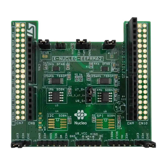
Introduction
The
X-NUCLEO-EEPRMA2
The expansion board acts as an external storage device that can be used to store data such as manufacturing traceability,
calibration, user settings, error flags, data logs and monitoring data to make applications more flexible and accurate.
The
X-NUCLEO-EEPRMA2
easily plugged to any
STM32 Nucleo
UM2665 - Rev 2 - February 2020
For further information contact your local STMicroelectronics sales office.
expansion board is designed for M24xx I²C and M95xx SPI EEPROM for data reading and writing.
expansion board is compatible with the Arduino UNO R3 connector pin assignment and can be
development board. You can mount the ST morpho connectors if required.
Figure 1.
X-NUCLEO-EEPRMA2 expansion board
UM2665
User manual
www.st.com
Advertisement
Table of Contents

Related Manuals for ST X-NUCLEO-EEPRMA2


Summary of Contents for ST X-NUCLEO-EEPRMA2
- Page 1 UM2665 User manual Getting started with the X-NUCLEO-EEPRMA2 standard I²C and SPI EEPROM memory expansion board based on M24xx and M95xx series for STM32 Nucleo Introduction X-NUCLEO-EEPRMA2 expansion board is designed for M24xx I²C and M95xx SPI EEPROM for data reading and writing.
-
Page 2: Acronyms And Abbreviations
UM2665 Acronyms and abbreviations Acronyms and abbreviations Table 1. List of acronyms Acronym Description EEPROM Electrically erasable programmable read only memory Mega Hertz Microcontroller unit Serial peripheral interface Inter-integrated circuit UM2665 - Rev 2 page 2/22... -
Page 3: Getting Started
Hardware requirements To use STM32 Nucleo development boards with the X-NUCLEO-EEPRMA2 expansion board, connect the boards as shown below. Figure 2. X-NUCLEO-EEPRMA2 expansion board connected to an STM32 Nucleo development board UM2665 - Rev 2 page 3/22... -
Page 4: System Requirements
The EEPROM communicates with the STM32 Nucleo development board host microcontroller through the SPI or I²C signals available on the Arduino UNO R3 connector. X-NUCLEO-EEPRMA2 has been designed to allow using any STM32 Nucleo board, although complete testing has been performed using the NUCLEO-F401RE NUCLEO-L053R8 boards. -
Page 5: Hardware Description And Configuration
Interconnection details X-NUCLEO-EEPRMA2 expansion board and the NUCLEO-L053R8 NUCLEO-F401RE board connection details are listed below. Table 2. X-NUCLEO-EEPRMA2 and NUCLEO-L053R8 connection details (left connector) Signal name NC IOREF RESET GND GND Connector name CN6 Power CN8 Analog Pin number NUCLEO-L053R8 MCU port... -
Page 6: Figure 1. X-Nucleo-Eeprma2 Expansion Board
UM2665 Interconnection details Table 3. X-NUCLEO-EEPRMA2 and NUCLEO-L053R8 connection details (right connector) Signal name AREF Connector name CN5 Digital CN9 Digital Pin number NUCLEO-L053R8 MCU port PB10 PA10 NUCLEO-L053R8 MCU signals X-NUCLEO-EEPRMA2 shield signals Table 4. X-NUCLEO-EEPRMA2 and NUCLEO-F401RE connection details (left connector) -
Page 7: Current Measurement
UM2665 Current measurement Table 5. X-NUCLEO-EEPRMA2 and NUCLEO-F401RE connection details (right connector) Signal name AREF Connector name CN5 Digital CN9 Digital Pin number NUCLEO-F401RE MCU port PB10 PA10 NUCLEO-F401RE MCU signals X-NUCLEO-EEPRMA2 shield signals Current measurement J1 can be used to monitor the I²C device power consumption, whereas J2 can be used to monitor the SPI device power consumption. -
Page 8: X-Nucleo-Eeprma2 Component Placement Details
UM2665 X-NUCLEO-EEPRMA2 component placement details X-NUCLEO-EEPRMA2 component placement details Figure 3. X-NUCLEO-EEPRMA2 component placement details Figure 4. X-NUCLEO-EEPRMA2 top view layout UM2665 - Rev 2 page 8/22... -
Page 9: Figure 5. X-Nucleo-Eeprma2 Bottom View Layout
UM2665 X-NUCLEO-EEPRMA2 component placement details Figure 5. X-NUCLEO-EEPRMA2 bottom view layout UM2665 - Rev 2 page 9/22... -
Page 10: Component Description
UM2665 Component description Component description M24XX Table 6. M24C02 details Feature Description Sales type M24C02-FMC6TG Package UFDFPN8 Single supply voltage 1.7 to 5.5 V (full temperature range) and 1.6 to 1.7 V (limited temperature range) Table 7. M24256 details Feature Description Sales type M24256-DFDW6TP... - Page 11 UM2665 M95XX Table 11. M95M04 details Feature Description Sales type M95M04-DRMN6TP Package Single supply voltage 1.8 to 5.5 V UM2665 - Rev 2 page 11/22...
-
Page 12: External Eeproms
Open J5 and J6 3V3 and VCC pins and short the EXT and VCC pins Note: External VCC can be used to power EEPROM with a different VCC for specific evaluations. Figure 6. I2C and SPI EEPROM soldered on the X-NUCLEO-EEPRMA2 expansion board External I2C EEPROM External SPI EEPROM UM2665 - Rev 2... -
Page 13: Bill Of Materials
UM2665 Bill of materials Bill of materials Table 12. X-NUCLEO-EEPRMA2 bill of materials Item Q.ty Ref. Part / Value Description Manufacturer Order code 2 KBIT 400 KHZ 2-Kbit serial I²C bus M24C02-FMC6TG UFDFPN8 EEPROM 256 KBIT 1 MHZ 256-Kbit serial I²C... - Page 14 UM2665 Bill of materials Item Q.ty Ref. Part / Value Description Manufacturer Order code R22, R32, 10 K ±5% 1/10 W Resistors Panasonic ERJ-2GEJ103X R33, R34 SMD0402 S1, S2, S3, S4, S5, S6, CLOSE Solder bridge S7, S20 S11, S15 OPEN Solder bridge S10, S13...
-
Page 15: Schematic Diagrams
Schematic diagrams Figure 7. X-NUCLEO-EEPRMA2 circuit schematic (1 of 4) M95_VCC M95_VCC FOR CURRENT MEASUREMENT U5_Sn M95_VCC 100nF M95_MISO M95_Hn HOLD M95_WPn M95_SCLK M95_MOSI M95_VCC M95_WPn M95040-RMC6TG (4Kb, DFN8 ) M95_VCC CON3 M95_VCC U6_Sn M95_VCC 100nF M95_MISO M95_Hn HOLD M95_WPn... -
Page 16: Figure 8. X-Nucleo-Eeprma2 Circuit Schematic (2 Of 4)
Figure 8. X-NUCLEO-EEPRMA2 circuit schematic (2 of 4) JJ11 M24_VCC FOR CURRENT MEASUREMENT CC11 1K R37 M24_VCC 100nF M24_WC M24_VCC M24_I2C_SCL M24_I2C_SDA SSSDA M24C02-FMC6TG (2Kb, DFN8 ) M24_I2C_SCL M24_VCC 3.3K M24_I2C_SDA M24_VCC 3.3K M24_VCC M24_VCC 100nF M24_WC M24_WC M24_VCC M24_I2C_SCL... -
Page 17: Figure 9. X-Nucleo-Eeprma2 Circuit Schematic (3 Of 4)
Figure 9. X-NUCLEO-EEPRMA2 circuit schematic (3 of 4) CN10 AREF RESET Figure 10. X-NUCLEO-EEPRMA2 circuit schematic (4 of 4) M24_I2C_SCL CLOSED M24_I2C_SDA CLOSED IOREF RESET AREF RESET AREF M95_SCLK CLOSED SCK/D13 M95_MISO CLOSED MISO/D12 M95_MOSI CLOSED MOSI/PWM/D11 CN5_3_U7_Sn CLOSED PWM/D10... -
Page 18: Revision History
UM2665 Revision history Table 13. Document revision history Date Revision Changes 03-Dec-2019 Initial release. Updated Figure 1. X-NUCLEO-EEPRMA2 expansion board Figure 2. X-NUCLEO-EEPRMA2 27-Feb-2020 expansion board connected to an STM32 Nucleo development board. UM2665 - Rev 2 page 18/22... -
Page 19: Table Of Contents
Current measurement............7 X-NUCLEO-EEPRMA2 component placement details ....... . 8 Component description . - Page 20 List of acronyms ..............2 Table 2. X-NUCLEO-EEPRMA2 and NUCLEO-L053R8 connection details (left connector) ..... . . 5 Table 3.
- Page 21 X-NUCLEO-EEPRMA2 component placement details ........
- Page 22 ST’s terms and conditions of sale in place at the time of order acknowledgement. Purchasers are solely responsible for the choice, selection, and use of ST products and ST assumes no liability for application assistance or the design of Purchasers’...
Need help?
Do you have a question about the X-NUCLEO-EEPRMA2 and is the answer not in the manual?
Questions and answers