Table of Contents
Advertisement
Quick Links
INTERFACE FEATURES
• Includes (4) high resolution 180-degree "fish-eye" cameras
• Exclusive "fish-eye" distortion correction
• Seamless 3D & 360° video merging
• Dynamic & intelligent view angle switching
• Includes calibration tools
• Independent camera calibration
iBEAM Vehicle Safety Systems
®
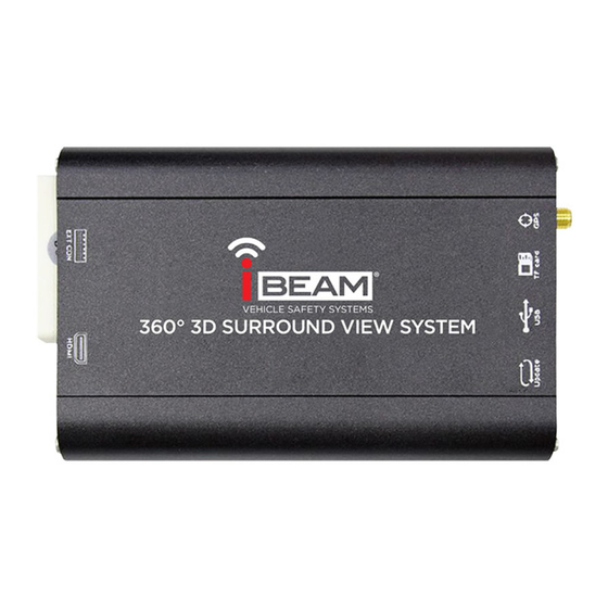
360-Degree 3D SVM Camera System with DVR
INTERFACE COMPONENTS
• TE-360-3D Interface
• TE-360-3D interface harness
• Remote control
• Remote control IR receiver
• Cameras (4)
• 3D video de-interlacing and noise reduction technology for CVBS
signal decoding
• Digital 1080p recorder supporting up to 32GB USB flash drive or SD card
• Smart power management to preserve battery power
• Automatic recording for up to 28 hours
iBEAMUSA.com
• 22mm hole-saw
• Calibration tape
• Side camera adjustment tool
© COPYRIGHT 2018 METRA ELECTRONICS CORPORATION
TE-360-3D
I N S TA L L AT I O N I N S T R U C T I O N S
TABLE OF CONTENTS
Introduction............................................................2
Safety tips...............................................................2
Installation ..........................................................2-3
Camera calibration............................................. 4-7
User settings .....................................................8-10
Digital video recording (DVR) . ............................. 11
Specifications . .......................................................12
Troubleshooting . ...................................................12
Layout . ...................................................................13
TOOLS REQUIRED
• Wire cutter • Crimp tool • Solder gun • Tape
• Connectors (example: butt-connectors, bell
caps, etc.)
CAUTION!
All accessories, switches, climate controls
panels, and especially air bag indicator lights must
be connected before cycling the ignition.
REV. 8/6/18 INSTTE-360-3D
b
Advertisement
Table of Contents

Subscribe to Our Youtube Channel
Related Manuals for iBeam TE-360-3D


Summary of Contents for iBeam TE-360-3D
-
Page 1: Table Of Contents
• Includes calibration tools • Automatic recording for up to 28 hours • Independent camera calibration CAUTION! All accessories, switches, climate controls panels, and especially air bag indicator lights must be connected before cycling the ignition. iBEAM Vehicle Safety Systems iBEAMUSA.com ® © COPYRIGHT 2018 METRA ELECTRONICS CORPORATION REV. 8/6/18 INSTTE-360-3D... -
Page 2: Introduction
INTRODUCTION INSTALLING THE TE-360-3D It is best to read the following steps beforehand to clearly understand what is to be expected, The I-Beam TE-360-3D is a 360-degree 3D Surround-View-Monitor (SVM) camera system that before permanently modifying the vehicle. Also, when unpacking the TE-360-3D, do not damage utilizes the latest high resolution 180-degree “fish-eye” cameras to monitor and digitally record the box it came in as it will be used as a tool to calibrate the cameras. a 360-degree surrounding view of the vehicle. Coupled with the latest software technology, all cameras are seamlessly merged to form a single real-time image. Cameras: Activating the turn signals will show the respective left-side or right-side camera image. The If possible, try to keep all the cameras at the same vertical height to maintain the same image front camera image can be shown by a quick flash of the high-beams. While in reverse gear aspect. The closer you can get to the same vertical height, the better the image will look when it the rear camera image will be shown, and will supersede all other cameras. All camera images is seamed together. shown will be through either an aftermarket radio, or a stand-alone monitor (not provided). • Front Camera: Using (2) stainless steel Phillips screws provided, install the camera labeled “front” to a location that is in the center of the front of the vehicle. Leave the adjustment Supporting up to a 32GB USB flash drive or SD card (both not included), the TE-360-3D can record screws loose until the camera has been adjusted. Once the camera has been adjusted, up to 28 hours of continuous 1080p recording, automatically while you are driving, and also tighten the screws. Route the cable into the vehicle, and then to the location where the while the vehicle is parked (24-hr. video loop). Recorded videos can be easily retrieved and TE-360-3D interface will be installed at. Use caution not to run wires next to places that will played back, and used as evidence if need be. be hot, and also moving mechanisms. • Rear Camera: Using (2) stainless steel Phillips screws provided, install the camera labeled “rear” to a location in the center of the rear of the vehicle. The license plate area in most SAFETY TIPS vehicles is a good location. Leave the adjustment screws loose until the camera has been adjusted. Once the camera has been adjusted, tighten the screws. Route the cable into the vehicle, and then to the location where the TE-360-3D interface will be installed at. - Page 3 INSTALLING THE TE-360-3D (CONT.) then Insert the camera through the hole, but do not clip the camera into the hole just yet. From the TE-360-3D interface: Route the cable into the door, and then to the location where the TE-360-3D interface will • Connect the Yellow RCA jack labeled AV-OUT to the aftermarket radio or stand-alone monitor be installed at. Leave the connector accessible inside the mirror to be able to disconnect the providing the camera image. Connect the Red wire to the reverse trigger wire from the radio/monitor. camera if ever need be. Note 1: If using a radio as a display screen, this wire must be connected to trigger the Note: A metal “U-shaped” adjustment tool is included with each camera. Make sure not to radio to display an image. accidentally throw this tool away while unpacking the cameras. Note 2: If using a stand-alone monitor as a display screen which has an HDMI input, use the HDMI output instead for a better image. Remote control IR receiver: • Install the IR receiver to a location where the remote control has a clear line of sight, and With the key in the off position: also no more than 48-inches away from where the TE-360-3D will be installed at. Route the • Connect the Black wire to chassis ground. • Install the interface to a location that is hidden, cable to the location where the TE-360-3D interface will be installed at.
-
Page 4: Camera Extension Cables
CAMERA CALIBRATION Applying the calibration tools: • Park the vehicle in a flat location, away from all obstacles. Apply the tape to the ground as shown. This is a very important step and the tape must be placed as accurate as possible to create a distortion free, seamless image. Have patience with this step. (Figure A, B, C) • Separate the TE-360-3D product box. The product box has an inner and outer shell. Each shell should be placed at one of the (2) reference points shown. Either B1 and B2 for the back camera, F1 and F2 for the front camera, L1 and L2 for the left camera, or R1 and R2 for the right camera. Whichever reference points are chosen will dictate the first camera to be calibrated. It would be best if the boxes were weighted down to avoid the wind from blowing them over. (Figure D) Continued on the next page (Figure C) (Figure A) (Figure B) (Figure D) 1.800.221.0932 iBEAMUSA.com... - Page 5 CAMERA CALIBRATION (CONT.) Remote control functions: Camera adjustment: Having a Helper to help aid in adjusting the cameras is highly advisable, but not required. While adjusting the front cameras, ensure both front doors are fully shut. Also note, having the front windows down would make it to where adjustments can be made from inside the vehicle. • Turn the key (or push to start button) to the accessory position to power on the TE-360-3D. • Press and hold the “Left-Arrow” button on the remote control until the left camera comes on. • Rotate the left camera so it will show an image from the rear of the vehicle. Clip the camera in. • Insert the metal “U-shaped” tool provided into the front and rear holes in the bezel of the camera. (Figure A) • Pull the tool and camera towards the left rear of the vehicle. The image on the screen should not show the vehicle. It should be just slightly away from the vehicle. Looking at the camera it should appear to be aiming between the front and rear tires, away from the vehicle. Keep Button Description Function adjusting the camera as needed to ensure the best image possible. The goal is to be able to view traffic in the vehicles blind spot. Once a satisfactory image is provided, continue onto (1) Mode Enter settings menu. the right camera. Once the right camera has In SVM Mode, long press for 2 seconds to enter 4-channel recording. been adjusted, ensure that both the left and (2) In Menu Mode, selects last menu option. right cameras have an equal looking image. In SVM Mode, short press enters front camera mode. • After the side cameras have been adjusted, Press again to get back to SVM mode.
- Page 6 CAMERA CALIBRATION (CONT.) Camera calibration parameter settings: • Press the “Mode” button to access the settings menu. The default password is “360”. applications where it is not possible to angle the cameras away from the vehicle. • Enter the Camera Calibration menu. • Adjust the merging angle and range as needed. Try to keep this setting as close to default as possible. Adjusting this too much will distort the seamed image. The merging angle is to • Enter 360 Tuning to access the parameter settings. be used for instances where the front or rear camera image does not meet up with the side • Select the correct size of the vehicle and adjust the vehicle position as needed. camera image. The merging range is for adjusting the side cameras. • Adjust the shadow area for each of the cameras as needed. Each increment is equal to 2-inches. Continued on the next page The shadow area will help to eliminate the vehicle from being portrayed in the final image for 1.800.221.0932 iBEAMUSA.com...
- Page 7 CAMERA CALIBRATION (CONT.) Camera calibration: Tip! The use of an HDTV, 32” and higher, will improve the ease and accuracy of the calibration process. • Press the “Mode” button to go back to the previous calibration point if need be. • From the Camera Calibration menu, enter the desired camera to be calibrated. • Once done, proceed onto the next camera to be calibrated. The TE-360-3D product box shells will need to be moved to the reference points for the next camera to be calibrated. • The calibration process will start when the cursor starts blinking. • Continue the process until all cameras have been calibrated. Once completed, press • Move the cursor to location 1 via the remote control. Press and hold to move quickly. “Merging Computation”, then “OK”, to begin the merging process. The merging process will • Once at location 1, press “OK” to mark the calibration point in the screen. take approximately 2 minutes to complete. The system will reboot automatically after the merging process is complete. • Continue onto the next calibration point, in order, 2 through 8. REV. 8/6/2018 INSTTE-360-3D...
-
Page 8: User Settings
USER SETTINGS Viewing Modes Function Settings Menu User Settings Window Configuration Menu Item List Options Description Will activate the appropriate left or right camera once a Turn Signal Trigger ON / OFF turn signal has been activated Allows the turn signals to trigger the radio/monitor to display Activate Turn Signal ON / OFF an image, if it is not already displaying the TE-360-3D image Emergency Blinker Allows the hazard switch to override the display ON / OFF Trigger on the radio/monitor Display a guideline overlay while in reverse gear Guideline Assistance ON / OFF 3D Dynamic Angle Function ON / OFF Sets either a dynamic or static angle image Continued on the next page 1.800.221.0932 iBEAMUSA.com... - Page 9 USER SETTINGS (CONT.) Interface Settings: Other Settings: Menu Item List Options Description Menu Item List Options Description Language Setting English / Chinese Set desired language Hazard Blinker 1Min/3Min/5Min/ Sets the Emergency Blinker duration time once the Trigger Duration 3S/5S/30S Emergency Blinker Trigger feature has been turned to “On” Vehicle Type Vehicle Type Set 3D car model Display Turn Delay 30S/1Min/3Min/5Min For setting the delay to the radio/monitor System Mode Setting Split Screen Trigger Delay 30S/1Min/3Min/5Min To delay the turn signal and reverse trigger Adjust The Screen Y Position -9 ~ +9 Pixel Adjusts the horizontal position Reversing / Turning Sets the duration time for the radio/monitor 30S/1Min/3Min/5Min...
- Page 10 Upgrade & Restore Menu Item List Options Description Menu Item List Options Description Default - N/A Saturation -9~+9 Adjust video saturation System Restore Default or User Preference User Preference - To restore user Brightness -9~+9 Adjust video brightness preferences Contrast -9~+9 Adjust video contrast For upgrading firmware in the Upgrade Options Upgrade 3D Mode TE-360-3D Sharpness -7~+8 Adjust video sharpness Check Hardware / Version Information -9~+9 Firmware / Software version 1.800.221.0932 iBEAMUSA.com...
-
Page 11: Digital Video Recording (Dvr)
DIGITAL VIDEO RECORDING (DVR) Recording Functions Recording Settings 1. Long press the “Mode” button to switch to the recording system menu. 2. Press the “OK” button to stop the current recording. 3. Use the “Up/Down” buttons to navigate between the recorded files. 4. Press the “OK” button to select the recorded file to playback. 5. The (4) cameras can be enlarged to full screen mode by pressing the “Left /Right/Up/ Down” buttons. Menu Item List Options Description Date To change system time Language English / Chinese To change system language Time Watermark ON / OFF To apply a time stamp on the recorded video Format Format SD card To format SD Card Factory Reset To reset the default settings Firmware Info To check firmware version REV. 8/6/2018 INSTTE-360-3D... -
Page 12: Specifications
Camera Sampling Frequency 74.52MHZ this problem. Resolution 1280x720 @ 30fps Signal Standard AHD2.0 (Nextchip) A portion of the picture after merging is mirrored SNR 83.5bB • If a factory camera will be used with the TE-360-3D, please confirm whether the image High Beam Optional from the sensor is mirrored or not. If mirrored, please choose the mirror function in the Trigger Input Left/Right Turn menu. Reverse G-sensor BM250E Bosch The corner portion of the display is blank Algorithm H.264 Baseline @ L3.1... -
Page 13: Layout
LAYOUT REV. 8/6/2018 INSTTE-360-3D... - Page 14 1.800.221.0932 iBEAMUSA.com...
- Page 15 REV. 8/6/2018 INSTTE-360-3D...
- Page 16 Log onto www.installerinstitute.com or call 800-354-6782 for more information and take steps toward a better tomorrow. Metra recommends MECP certified technicians iBEAM Vehicle Safety Systems iBEAMUSA.com ® © COPYRIGHT 2018 METRA ELECTRONICS CORPORATION REV. 8/6/18 INSTTE-360-3D...
Need help?
Do you have a question about the TE-360-3D and is the answer not in the manual?
Questions and answers