La Cornue AlberTine 90 User Manual & Installation & Service Instructions
Dual fuel cooker
Hide thumbs
Also See for AlberTine 90:
- User manual & installation & service instructions (64 pages) ,
- User manual (56 pages) ,
- User's manual & installation instructions (52 pages)

Related Manuals for La Cornue AlberTine 90


Summary of Contents for La Cornue AlberTine 90
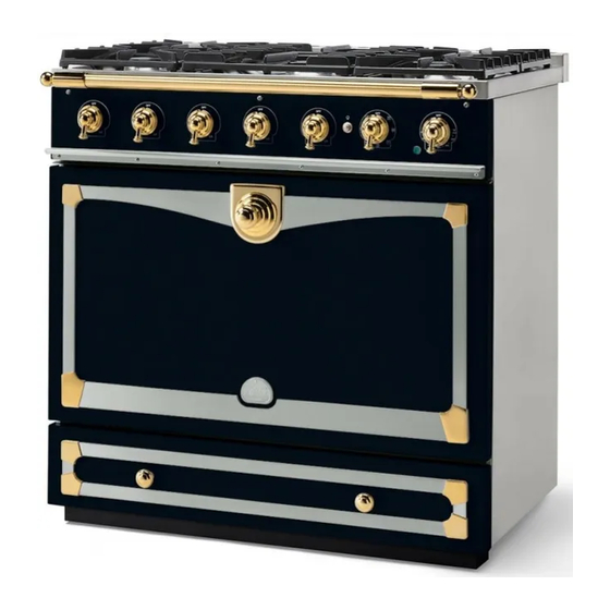
- Page 1 AlberTine 90 Dual Fuel Cooker AlberTine User Guide & Installations & Service Instructions AUSTRALIA U111145 - 01...
-
Page 3: Table Of Contents
Contents Before You Start... Troubleshooting Personal Safety Service and Spares Electrical Connection Safety Installation If You Smell Gas Peculiar Smells Safety Requirements and Regulations Cooling Fan Provision of Ventilation Ventilation Location of cooker Maintenance Positioning the Cooker Grill/Glide-out Grill™ Care Moving the cooker Cooker Care Lowering the two rear rollers... -
Page 5: Before You Start
Before You Start... Your cooker should give you many years of The cooker should not be placed on a base. • trouble-free cooking if installed and operated This appliance is designed for domestic • correctly. It is important that you read this cooking only. -
Page 6: Electrical Connection Safety
Always keep combustible materials, e.g. Make sure that the gas supply is turned • • curtains, and flammable liquids a safe on and that the cooker is wired in and distance away from the cooker. switched on. DO NOT spray aerosols in the vicinity of In your own interest and that of safety, it is •... -
Page 7: Cooling Fan
WARNING Cooling Fan : Use only hob guards designed • by the manufacturer of the cooking This appliance may have a cooling fan. When appliance or indicated by the manufacturer the grill or ovens are in operation the fan will of the appliance in the instructions for use run to cool the fascia and control knobs. - Page 8 DO NOT use the top of the flue (the slot • Fig. 1.1 along the back of the cooker) for warming plates, dishes, drying tea towels or softening butter. DO NOT use water on grease fires and • ArtNo.324-0001 Steam burst never pick up a flaming pan.
-
Page 9: Grill/Glide-Out Grill™ Care
Make sure the shelves are pushed firmly Accessible parts may be hot when the grill • • to the back of the oven. DO NOT close the is in use. Young children should be kept door against the oven shelves. away DO NOT use aluminium foil to cover •... - Page 10 DO NOT use any abrasive substances on • the grill and grill parts. DO NOT put the side runners in a • dishwasher. DO NOT put the burner heads in a • dishwasher. NEVER use caustic or abrasive cleaners as •...
-
Page 11: Overview
English Overview Fig. 2.1 AlberTine Your 90 cm dual fuel cooker (Fig. 2.1) has the following Fig. 2.2 features: 5 hotplate burners including a wok burner A control panel Main multi-function oven Storage drawer Cooktop Burners ArtNo.280-0101 - Knob Press In EU Before using the cooktop make sure all burners are in place and all the pan supports on the cooker are properly placed. -
Page 12: Igniting Cooktop Burners Without
English OFF position and wait one minute, then try again this time Fig. 2.3 holding in the control knob for slightly longer. Adjust the flame height to suit by turning the knob counter- clockwise (Fig. 2.3). On this cooker the low position is beyond high, not between high and off. -
Page 13: Energy Saving Feature
English Energy Saving Feature n Warning! The oven has a divider feature (Fig. 2.9). When this is in place Take great care when removing the divider not to scratch only one half of the oven is heated and only the right-hand the inner glass door surface. -
Page 14: Multi-Function Ovens
English Multi-function Ovens Fig. 2.12 Multi-function ovens have an oven fan and oven fan element, as well as two extra heating elements (Fig. 2.12). One element is in the top of the oven and the second is under the oven base. Take care to avoid touching the top element and element deflector when placing or removing items from the oven. -
Page 15: Multi-Function Oven Modes
English Multi-function Oven Modes Fan Assisted Oven (Fig. 2.13) This function operates the fans, circulating air heated Defrost by the elements at the top and the base of the oven. The combination of fan and conventional cooking This function operates the fan(s) to circulate cold air ArtNo.030-0014 - Top &... -
Page 16: Operating The Oven
English Operating the Oven Fig. 2.14 The multi-function oven has two controls: a function selector ArtNo.281-0027 Knob and Symbols and a temperature setting knob (Fig. 2.14). Turn the function selector control to a cooking function. This is the convection oven setting (Fig. 2.15). Turn the oven temperature knob to the temperature you need. -
Page 17: Accessories
English Accessories Fig. 2.17 Fig. 2.18 Oven Shelves Each cooker is supplied with: • 1x full capacity telescopic shelf with runners (Fig. 2.17) • 1x full capacity shelf with grill tray and cradle (Fig. 2.18) • 1x pastry tray (Fig. 2.19) Fig. -
Page 18: Storage
English To Fit a Shelf to the Telescopic Shelf Runners Fig. 2.26 Slide the telescopic runners forward until they stop. Holding the shelf above the runners, tilt the front downward and locate into the front of the runners. Lay the shelf flat. Press on the rear of the shelf to secure in place. -
Page 19: Cooking Tips
English Cooking tips Cooking with a multifunction oven General oven tips Remember: not all modes are suitable for all food types. The The wire shelves should always be pushed firmly to the back oven cooking times given are intended for a guide only. of the oven. -
Page 20: Cooking Table
Cooking Table The oven control settings and cooking times given in the table below are intended to be used as a guide only. Individual tastes may require the temperature to be altered to provide a preferred result. Top (T) ArtNo.050-0007 Centre (C) Oven shelf positions Food is cooked at lower temperature in a fan oven than in a conventional oven. -
Page 21: Cleaning Your Cooker
English Cleaning Your Cooker Isolate the electricity supply before carrying out any major Fig. 5.1 cleaning. Allow the cooker to cool. Never use paint solvents, washing soda, caustic cleaners, biological powders, bleach, chlorine based bleach cleaners, coarse abrasives or salt. ArtNo.311-0028 - Burner head off Do not mix different cleaning products –... -
Page 22: Stainless Steel Main Top
English ‘pips’; these fit into the two notches in the burner base Fig. 5.4 (Fig. 5.3). Check burner ports are not blocked. If blockage occurs, remove stubborn particles using a piece of fuse wire. Stainless Steel Main Top Lift away pots or pans from main top. Remove the pan supports from spillage area and carefully place in a sink of warm soapy water. -
Page 23: Cleaning Table
English Cleaning Table Cleaners listed (Table 5.1) are available from supermarkets or electrical retailers as stated. For enamelled surfaces use a cleaner that is approved for use on vitreous enamel. Regular cleaning is recommended. For easier cleaning, wipe up any spillages immediately. Hotplate Part Finish... -
Page 24: Troubleshooting
Troubleshooting Hotplate/Cooktop ignition or hotplate burners faulty Food is cooking too slowly, too quickly, or burning Is the power on? If not, there maybe something wrong with Cooking times may differ from your previous oven. the power supply. Check that you are using the recommended temperatures Are the sparker (ignition electrode) or burner ports blocked and shelf positions –... - Page 25 Oven light is not working Fig. 6.1 The bulb has probably burnt out. You can buy a replacement bulb (which is not covered under the warranty) from a good electrical shop. Ask for a 40 W - 230 V halogen lamp (G9) (Fig. 6.1). Turn off the power at the circuit breaker.
-
Page 26: Service And Spares
INSTALLATION Check the appliance is electrically safe when you have finished. Service and Spares Firstly, please complete the appliance details below and keep them safe for future reference – this information will enable us to accurately identify the particular appliance and help us to help you. Filling this in now will save time and inconvenience if you later have a problem with the appliance. -
Page 27: Installation
INSTALLATION Check the appliance is electrically safe and gas sound when you have finished. Installation Safety Requirements and Provision of Ventilation Regulations This appliance is not connected to a combustion products evacuation device. Particular attention shall be given to the You must be aware of the following safety requirements &... - Page 28 INSTALLATION Check the appliance is electrically safe and gas sound when you have finished. You will need the following equipment to complete the Checking the Parts: cooker installation satisfactorily: 1x full capacity telescopic shelf Pan Supports • Stability bracket: If the cooker is to be supplied with gas with runners through a flexible hose, a stability bracket or chain must be fitted.
-
Page 29: Positioning The Cooker
INSTALLATION Check the appliance is electrically safe and gas sound when you have finished. Positioning the Cooker Fig. 8.1 Fig. 8.1 and Fig. 8.2 show the minimum recommended 75 mm 75 mm distance from the cooker to nearby surfaces. 800 mm The cooker should not be placed on a base. -
Page 30: Completing The Move
INSTALLATION Check the appliance is electrically safe and gas sound when you have finished. Completing the move Fig. 8.5 Fig. 8.6 Unfold the rear edge of the cardboard base tray. Open the oven doors so that you can get a good grip on the bottom of the fascia panel as you move the oven (Fig. -
Page 31: Fitting The Stability Bracket
INSTALLATION Check the appliance is electrically safe and gas sound when you have finished. Fitting the stability bracket Fig. 8.9 Suitable stability devices are shown in Fig. 8.9, Fig. 8.10 and Stability chain Fig. 8.11. If you are using a stability chain (Fig. 8.9) then the chain should be kept as short as is practicable and fixed firmly to the rear of the cooker. -
Page 32: Gas Connection
INSTALLATION Check the appliance is electrically safe and gas sound when you have finished. Gas Connection Fig. 8.15 Conversion to Another Gas If the appliance is to be converted to another gas do the conversion at this point. See ‘Conversion to LP Gas’ . Gas Connection This must be in accordance with the relevant standards. -
Page 33: Electrical Connection
INSTALLATION Check the appliance is electrically safe and gas sound when you have finished. Electrical Connection Current Operated Earth Leakage Breakers This appliance must be installed by a qualified electrician The combined use of your cooker and other domestic to comply with with current AS/NZS 3000 Wiring Rules and appliances may cause nuisance tripping, so we recommend regulations in force. -
Page 34: Fixed Wiring
INSTALLATION Check the appliance is electrically safe and gas sound when you have finished. Fixed Wiring Fig. 8.18 Disconnect from the mains supply. For connection to fixed wiring, i.e. flexible conduit, remove the electrical terminal cover on the back panel. Using the two screws, fix the strain relief bracket in position. -
Page 35: Final Fitting And Checks
INSTALLATION Check the appliance is electrically safe when you have finished. Final fitting and checks Hotplate check Fig. 9.1 Check each burner in turn. There is a flame supervision device (FSD) that stops the flow of gas to the burner if the flame goes out. -
Page 36: Fitting The Drawer
INSTALLATION Check the appliance is electrically safe and gas sound when you have finished. Fitting the drawer Removing the drawer... -
Page 37: Conversion To Lp Gas
INSTALLATION Check the appliance is electrically safe and gas sound when you have finished. 10. Conversion to LP Gas Important Fig. 10.1 • Observe all governing codes and ordinances. Burner head Burner head Burner Ring • The range must be properly grounded. Burner ring •... - Page 38 INSTALLATION Check the appliance is electrically safe and gas sound when you have finished. Save the orifices removed from the appliance for future use. Fig. 10.4 To install the new orifices; see Table 12. 1 for orifice details. Insert the new orifice into the open end of the rubber tube which is attached to the socket wrench.
-
Page 39: Pressure Testing
INSTALLATION Check the appliance is electrically safe and gas sound when you have finished. Set the Governor Fig. 10.6 NOTE: To avoid exterior damage to the storage drawer. Place a soft cushioned mat on the floor. To access the governor, remove the storage drawer (see Removing the drawer). -
Page 40: Servicing
WARNING – SERVICING TO BE CARRIED OUT ONLY BY AN AUTHORISED PERSON Disconnect from electricity and gas before servicing. Check appliance is safe when you have finished. 11. Servicing BEFORE SERVICING ANY GAS CARRYING Fig. 11.1 COMPONENTS. TURN OFF THE GAS SUPPLY DO NOT modify this appliance! Check the appliance is gas sound after completion of service. -
Page 41: Controls
WARNING – SERVICING TO BE CARRIED OUT ONLY BY AN AUTHORISED PERSON Disconnect from electricity and gas before servicing. Check appliance is safe when you have finished. 3. Controls To replace a hotplate control taps DISCONNECT FROM THE ELECTRICITY SUPPLY. To change the light switch Remove the control panel (Fig. -
Page 42: Ovens
WARNING – SERVICING TO BE CARRIED OUT ONLY BY AN AUTHORISED PERSON Disconnect from electricity and gas before servicing. Check appliance is safe when you have finished. 4. Ovens Fig. 11.3 To replace an oven thermostat DISCONNECT FROM THE ELECTRICITY SUPPLY. NOTE: There are 2 thermostats in the oven. - Page 43 WARNING – SERVICING TO BE CARRIED OUT ONLY BY AN AUTHORISED PERSON Disconnect from electricity and gas before servicing. Check appliance is safe when you have finished. 1.1 To Replace a Fan Oven Element Fig. 11.5 DISCONNECT FROM THE ELECTRICITY SUPPLY. Remove the inner back (see 3).
-
Page 44: Doors
WARNING – SERVICING TO BE CARRIED OUT ONLY BY AN AUTHORISED PERSON Disconnect from electricity and gas before servicing. Check appliance is safe when you have finished. 5. Doors Fig. 11.8 Removing the oven door To remove the oven door, open the door fully. Swivel the locking ‘U’... -
Page 45: Circuit Diagram
English 12. Circuit Diagram r (flag) Clear boots r (f) clear clear clear r (flag) r (flag) Black boots Code Description Code Description Code Color Left Hand Oven Multifunction Switch Ignition Switches Blue Left Hand Oven Base Element Ignition Switch Brown Left Hand Oven Fan Element Spark Generator... -
Page 46: Technical Data
Operating Pressure at appliance test point Natural Gas 1 kPa Propane 2.54 kPa Dimensions Model ALBERTINE 90 Dual Fuel Overall height minimum 912 mm maximum 937 mm Overall width 900 mm Overall depth 653 mm excluding handles, 729 mm including handles... - Page 47 NOTE...
Need help?
Do you have a question about the AlberTine 90 and is the answer not in the manual?
Questions and answers