Table of Contents
Advertisement
Advertisement
Table of Contents

Subscribe to Our Youtube Channel
Related Manuals for La Cornue Chateau 150 G45


Summary of Contents for La Cornue Chateau 150 G45
- Page 1 Installation guide Safety Rules Château G4 Range with the new vaulted ovens and the patented innovation, the RCC disk. Grand Palais 180 • Château 165 • Château 150 Grand Châtelet 150 • Grand Châtelet 135 Château 120 • Châtelet 120 Grand Castel 90 •...
- Page 2 Dear Customer, Thank you for purchasing a La Cornue cooker. We hope that you really enjoy preparing delicious meals with it. The aim of this installation guide is to familiarise you with the potential of a professional quality appliance designed for domestic use and to facilitate its upkeep.
- Page 3 Instructions for Use, to check that you are using the appliance correctly. If you are still having difficulty, contact your retailer. LA CORNUE HEADQUARTERS AND WORKSHOP 14, rue du Bois du Pont - Z.I. Les Béthunes 95310 SAINT OUEN L’AUMONE...
-
Page 4: Table Of Contents
CONTENTS CONTENTS ..........................4 WARNINGS SAFETY RULES ..................7-12 DESCRIPTION ........................13 GENERAL DESCRIPTION ..................13 ENERGY POWER AND GAS FLOW RATES ............15 POWER RATINGS FOR THE ELECTRICAL ELEMENTS ........16 RATING PLATE ......................17 LE GRAND PALAIS 180 - G48, T48 ................... 18 DIMENSIONS ...................... - Page 5 POWER FOR GAS AND ELECTRIC COOKERS ............38 POWER FOR GAS AND ELECTRIC COOKTOPS ........... 39 COOKER CONNECTIONS ..................40 COOKTOP CONNECTIONS ..................40 LE CHATEAU® 120 - G42, T42 ..................41 DIMENSIONS ......................41 HOB CONFIGURATIONS ..................42 POWER FOR GAS AND ELECTRIC COOKERS ............43 POWER FOR GAS AND ELECTRIC COOKTOPS ...........
- Page 6 HEIGHT ADJUSTMENT ..................... 67 CONNECTIONS ........................68 ELECTRICAL CONNECTIONS ................. 68 GAS CONNECTION ....................69 IGNITION – ADJUSTMENTS ..................... 72 STARTING WITH THE COOKTOP ELEMENTS ............. 72 GAS HOBS WITH ELECTRIC IGNITION (SMALL, LARGE AND MAXI BURNER) ......................... 72 HOTPLATE OR LAVA ROCK GRILL WITH ELECTRIC IGNITION ..... 73 INDUCTION CERAMIC HOB ................
-
Page 7: Warnings Safety Rules
WARNINGS SAFETY RULES This appliance must be installed by a qualified professional in accordance with the current regulations in the country where the appliance is installed and must only be used in a well ventilated area. Read the guides before installing and using this appliance. Appliance categories (see pt. - Page 8 WARNINGS. SAFETY RULES This appliance can be used by children aged from 8 years and above and persons with reduced physical, sensory or mental capabilities or lack of experience and knowledge if they have been given supervision or instruction concerning use of the appliance in a safe way and understand the hazards involved.
- Page 9 WARNINGS. SAFETY RULES Do not spray aerosols in the vicinity of the cooker while it is on. Do not store or use combustible materials or flammable liquids in the vicinity of this appliance. Take great care when heating fats and oils, as they will ignite if they get too hot. Use a deep fat thermometer whenever possible to prevent overheating fat beyond the smoking point.
- Page 10 WARNINGS. SAFETY RULES Never cover the slits, apertures or holes in the bottom part of the appliance, and never cover the grills with products such as aluminium foil; doing so would prevent air circulation inside the oven and the aluminium foil could cause heat to build up leading to a risk of fire. Do not use the oven for storage.
- Page 11 WARNINGS. SAFETY RULES Use the right size pan. This appliance is equipped with burners of different sizes. Use utensils with flat bottoms. Do not use unstable pans and position the handles away from the edge of the cooktop. Make sure the flames are under the pans. It’s not safe to let the flames burn up the sides of the pan;...
-
Page 12: Warnings Safety Rules
WARNINGS. SAFETY RULES ATTENTION : Installation en Suisse Les directives suivantes sont à prendre en considération lors du montage et de l'installation : directives Gaz de la SSIGE G1 (2005) directives CFST N° 1942: Gaz liquéfié, partie 2 (CFST: Commission d'examen Fédérale de coordination pour la Sécurité au Travail) prescriptions de l'Association des Etablissements cantonaux d'Assurance Incendie (AEAI) WARNING: Installation in Switzerland... -
Page 13: Description
DESCRIPTION 1. GENERAL DESCRIPTION There are nine models in the “Château” cooker range with vaulted oven: Le Grand Palais 180 - G48 Model comprising two large vaulted ovens (gas or electric on the left and electric on the right) and a cooktop. Width: 180cm. - Page 14 There are seven models in the “Château” range of hobs: Grand Palais 180 cooktop -T48 Width: 180cm. ® Château 165 cooktop - T46 Width: 165 cm. ® Château 150 cooktop - T45 Width: 150 cm. Grand Châtelet 135 cooktop - T43 Width: 135 cm.
-
Page 15: Energy Power And Gas Flow Rates
2. ENERGY POWER AND GAS FLOW RATES All of our appliances belong to Category II and are designed for gases from the second and third groups. The gas used can be either natural gas G20 pressure 20 mbar (2 kPa) and G25 pressure 20 or 25 mbar (2 or 2.5 kPa), propane G31 pressure 37 mbar (3.7 kPa) or butane G30/propane G31 pressure 28-30, 37 and 50 mbar (2.8-3 and 5 kPa), depending on availability. -
Page 16: Power Ratings For The Electrical Elements
Large induction glass-ceramic plate (one cooking area Ø 280 mm).... 3700 W Large “La Cornue” Teppan-Yaki..............2000 W (dimensions: 419 x 478 mm) Small “La Cornue” Teppan-Yaki ...........…....1600 W (dimensions: 284 x 478 mm) “C - G4 INSTALLATION GUIDE FOR HÂTEAU”... -
Page 17: Rating Plate
4. RATING PLATE The rating plate of your appliance is on the bottom-left, on the toe kick behind the storage drawer, or inside the spill tray for the château 120 models and for the cooktops. To see this rating plate, pull out the storage drawer or spill tray. You will find on this plate the name and address of the manufacturer as well as the following information: 1) Kind of appliance (model) -
Page 18: Le Grand Palais 180 - G48, T48
LE GRAND PALAIS 180 - G48, T48 1. DIMENSIONS Cooker - G48: Cooker weight: 280 - 320 kg depending on the model Cooktop - T48: Cooktop weight: 100 - 130 kg depending on the model “C - G4 INSTALLATION GUIDE FOR HÂTEAU”... -
Page 19: Hob Configurations
2. HOB CONFIGURATIONS 2 gas burners (small burner at the rear) 1 gas hotplate 1 maxi burner 2 gas burners (small burner at the rear) 2 gas burners (small burner at the rear) 1 gas hotplate 1 large electric teppan-yaki 1 induction hob with two cooking areas 2 gas burners (small burner at the rear) 1 gas hotplate... -
Page 20: Power For Gas And Electric Cookers
LE GRAND PALAIS 180 - G48 3. POWER FOR GAS AND ELECTRIC COOKERS GAS SUPPLY ELECTRIC SUPPLY INFORMATION INFORMATION Volume Flow Mass Flow 220 - 240 V a.c. 400 V a.c. 3N Rate Rate power supply power supply /hour kg/h (1 Ph + N + G) (3 Ph + N + G) Model... -
Page 21: Power For Gas And Electric Cooktops
LE GRAND PALAIS 180 - T48 4. POWER FOR GAS AND ELECTRIC COOKTOPS GAS SUPPLY ELECTRIC SUPPLY INFORMATION INFORMATION Volume Flow Mass Flow 220 - 240 V a.c. 400 V a.c. 3N Rate Rate power supply power supply /hour kg/h (1 Ph + N + G) (3 Ph + N + G) Model... -
Page 22: Cooker Connections
LE GRAND PALAIS 180 COOKER CONNECTIONS Rear view INLET COOKTOP CONNECTIONS Rear view INLET The gas inlet only exists on models with at least one gas module on the hob or a gas oven. The number of electric terminal blocks depends on the make-up of the model. See “power for gas and electric cooktops”... -
Page 23: Le Chateau® 165 - G46, T46
LE CHATEAU® 165 - G46, T46 1. DIMENSIONS Cooker - G46: Cooker weight: 260 – 290 kg. depending on the model Cooktop - T46: Cooktop weight: 90 – 130 kg. depending on the model “C - G4 INSTALLATION GUIDE FOR HÂTEAU”... -
Page 24: Hob Configurations
2. HOB CONFIGURATIONS 2 gas burners (small burner at the rear) 1 gas hotplate 1 maxi burner 2 gas burners (small burner at the rear) 2 gas burners (small burner at the rear) 1 gas hotplate 1 large electric teppan-yaki 1 induction hob with two cooking areas 2 gas burners (small burner at the rear) 1 gas hotplate... -
Page 25: Power For Gas And Electric Cookers
LE CHÂTEAU 165® – G46 POWER FOR GAS AND ELECTRIC COOKERS GAS SUPPLY ELECTRIC SUPPLY INFORMATION INFORMATION 220 - 240 V a.c. 400 V a.c. 3N Volume Flow Mass Flow Rate Rate power supply power supply /hour kg/h (1 Ph + N + G) (3 Ph + N + G) Model Nominal... -
Page 26: Power For Gas And Electric Cooktops
LE CHÂTEAU 165® - T46 POWER FOR GAS AND ELECTRIC COOKTOPS GAS SUPPLY ELECTRIC SUPPLY INFORMATION INFORMATION 220 - 240 V a.c. 400 V a.c. 3N Volume Flow Mass Flow Rate Rate power supply power supply /hour kg/h (1 Ph + N + G) (3 Ph + N + G) Model Nominal... -
Page 27: Cooker Connections
LE CHÂTEAU 165® 5. COOKER CONNECTIONS Rear view TERMINAL BLOCK 3 INLET INLET TERMINAL TERMINAL BLOCK 1 BLOCK 2 6. COOKTOP CONNECTIONS Rear view INLET TERMINAL TERMINAL BLOCK 1 BLOCK 2 INLET The gas inlet only exists on models with at least one gas module on the hob or a gas oven. The number of electric terminal blocks depends on the make-up of the model. -
Page 28: Le Chateau® 150 - G45, T45
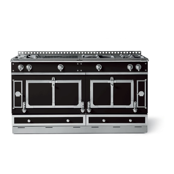
LE CHATEAU® 150 - G45, T45 1. DIMENSIONS Cooker - G45: Cooker weight: 250 – 280 kg. depending on the model Cooktop - T45: Cooktop weight: 80 – 110 kg. depending on the model “C - G4 INSTALLATION GUIDE FOR HÂTEAU”... -
Page 29: Hob Configurations
2. HOB CONFIGURATIONS 2 gas burners (small burner at the rear) 1 gas hotplate 1 gas lava rock grill 1 large electric teppan-yaki 2 gas burners (small burner at the rear) 1 gas hotplate 1 maxi burner 2 gas burners (small burner at the rear) 2 gas burners (small burner at the rear) 1 gas hotplate 1 large electric teppan-yaki... -
Page 30: Power For Gas And Electric Cookers
LE CHÂTEAU 150® – G45 3. POWER FOR GAS AND ELECTRIC COOKERS GAS SUPPLY ELECTRIC SUPPLY INFORMATION INFORMATION 220 - 240 V a.c. 400 V a.c. 3N Volume Flow Mass Flow Rate Rate power supply power supply /hour kg/h (1 Ph + N + G) (3 Ph + N + G) Model Nominal... -
Page 31: Power For Gas And Electric Cooktops
LE CHÂTEAU 150® – T45 4. POWER FOR GAS AND ELECTRIC COOKTOPS GAS SUPPLY ELECTRIC SUPPLY INFORMATION INFORMATION 220 - 240 V a.c. 400 V a.c. 3N Volume Flow Mass Flow Rate Rate power supply power supply /hour kg/h (1 Ph + N + G) (3 Ph + N + G) Model Nominal... -
Page 32: Cooker Connections
LE CHÂTEAU 150® 5. COOKER CONNECTIONS Rear view TERMINAL BLOCK 3 INLET TERMINAL INLET TERMINAL BLOCK 2 BLOCK 1 6. COOKTOP CONNECTIONS Rear view INLET TERMINAL TERMINAL BLOCK 1 INLET BLOCK 2 The gas inlet only exists on models with at least one gas module on the hob or a gas oven. The number of electric terminal blocks depends on the make-up of the model. -
Page 33: Le Grand Chatelet 150 - G44
LE GRAND CHATELET 150 - G44 1. DIMENSIONS Cooker - G44: Cooker weight: 250 – 280 kg. depending on the model 2. HOB CONFIGURATIONS See page 29 “C - G4 INSTALLATION GUIDE FOR HÂTEAU” RANGE 08NOTINSTALG4/EN - 3... -
Page 34: Power For Gas And Electric Cookers
LE GRAND CHATELET 150 – G44 3. POWER FOR GAS AND ELECTRIC COOKERS GAS SUPPLY ELECTRIC SUPPLY INFORMATION INFORMATION 220 - 240 V a.c. 400 V a.c. 3N Volume Flow Mass Flow Rate Rate power supply power supply /hour kg/h (1 Ph + N + G) (3 Ph + N + G) Model... -
Page 35: Cooker Connections
LE GRAND CHATELET 150 4. COOKER CONNECTIONS Rear view TERMINAL BLOCK 2 INLET INLET TERMINAL BLOCK 1 The gas inlet only exists on models with at least one gas module on the hob or a gas oven. The number of electric terminal blocks depends on the make-up of the model. See “power for gas and electric cooktops”... -
Page 36: Le Grand Chatelet 135 - G43, T43
LE GRAND CHATELET 135 - G43, T43 1. DIMENSIONS Cooker - G43: Cooker weight: 200 – 220 kg. depending on the model Cooktop - T43: Cooktop weight: 80 – 100 kg. depending on the model “C - G4 INSTALLATION GUIDE FOR HÂTEAU”... -
Page 37: Hob Configurations
2. HOB CONFIGURATIONS 2 gas burners (small burner at the rear) 1 gas hotplate 2 gas burners (small burner at the rear) 2 gas burners (small burner at the rear) 1 maxi burner 2 gas burners (small burner at the rear) 2 gas burners (small burner at the rear) 1 gas hotplate 1 large electric teppan-yaki... -
Page 38: Power For Gas And Electric Cookers
LE CHATELET 135 – G43 3. POWER FOR GAS AND ELECTRIC COOKERS GAS SUPPLY ELECTRIC SUPPLY INFORMATION INFORMATION Volume Flow Mass Flow 220 - 240 V a.c. 400 V a.c. 3N Rate Rate power supply power supply /hour kg/h (1 Ph + N + G) (3 Ph + N + G) Model Nominal... -
Page 39: Power For Gas And Electric Cooktops
LE CHATELET 135 – T43 4. POWER FOR GAS AND ELECTRIC COOKTOPS GAS SUPPLY ELECTRIC SUPPLY INFORMATION INFORMATION Volume Flow Mass Flow 220 - 240 V a.c. 400 V a.c. 3N Rate Rate power supply power supply /hour kg/h (1 Ph + N + G) (3 Ph + N + G) Model Nominal... -
Page 40: Cooker Connections
LE CHATELET 135 5. COOKER CONNECTIONS Rear view TERMINAL BLOCK 3 INLET INLET TERMINAL TERMINAL BLOCK 2 BLOCK 1 COOKTOP CONNECTIONS Rear view INLET TERMINAL TERMINAL BLOCK 1 INLET BLOCK 2 The gas inlet only exists on models with at least one gas module on the hob or a gas oven. The number of electric terminal blocks depends on the make-up of the model. -
Page 41: Le Chateau® 120 - G42, T42
LE CHATEAU® 120 - G42, T42 1. DIMENSIONS Cooker - G42: Cooker weight: 200 – 220 kg. depending on the model Cooktop - T42: Cooktop weight: 80 – 90 kg. depending on the model “C - G4 INSTALLATION GUIDE FOR HÂTEAU”... -
Page 42: Hob Configurations
HOB CONFIGURATIONS 2 gas burners (small burner at the rear) 1 gas hotplate 2 gas burners (small burner at the rear) 2 gas burners (small burner at the rear) 1 maxi burner 2 gas burners (small burner at the rear) 2 gas burners (small burner at the rear) 1 gas hotplate 1 gas lava rock grill... -
Page 43: Power For Gas And Electric Cookers
LE CHÂTEAU 120® – G42 POWER FOR GAS AND ELECTRIC COOKERS GAS SUPPLY ELECTRIC SUPPLY INFORMATION INFORMATION 220 - 240 V a.c. 400 V a.c. 3N Volume Flow Mass Flow Rate Rate power supply power supply /hour kg/h (1 Ph + N + G) (3 Ph + N + G) Model Nominal... -
Page 44: Power For Gas And Electric Cooktops
LE CHÂTEAU 120® – T42 4. POWER FOR GAS AND ELECTRIC COOKTOPS GAS SUPPLY ELECTRIC SUPPLY INFORMATION INFORMATION 220 - 240 V a.c. 400 V a.c. 3N Mass Flow Volume Flow Rate power supply power supply /hour Rate kg/h (1 Ph + N + G) (3 Ph + N + G) Model Nominal... -
Page 45: Cooker Connections
LE CHÂTEAU 120® 5. COOKER CONNECTIONS Rear view TERMINAL BLOCK 3 TERMINAL BLOCK 2 GAS INLET TERMINAL BLOCK 1 INLET COOKTOP CONNECTIONS Rear view INLET INLET TERMINAL TERMINAL BLOCK 1 BLOCK 2 The gas inlet only exists on models with at least one gas module on the hob or a gas oven. The number of electric terminal blocks depends on the make-up of the model. -
Page 46: Le Chatelet 120 - G41
LE CHATELET 120 - G41 1. DIMENSIONS Cooker - G41: Cooker weight: 200 – 220 kg. depending on the model “C - G4 INSTALLATION GUIDE FOR HÂTEAU” RANGE 08NOTINSTALG4/EN - 3... -
Page 47: Hob Configurations
2. HOB CONFIGURATIONS 2 gas burners (small burner at the rear) 1 gas hotplate 2 gas burners (small burner at the rear) 2 gas burners (small burner at the rear) 1 maxi burner 2 gas burners (small burner at the rear) 2 gas burners (small burner at the rear) 1 gas hotplate 1 gas lava rock grill... -
Page 48: Power For Gas And Electric Cookers
LE CHATELET 120 – G41 3. POWER FOR GAS AND ELECTRIC COOKERS GAS SUPPLY ELECTRIC SUPPLY INFORMATION INFORMATION 220 - 240 V a.c. 400 V a.c. 3N Volume Flow Mass Flow Rate Rate power supply power supply /hour kg/h (1 Ph + N + G) (3 Ph + N + G) Model Nominal... -
Page 49: Cooker Connections
LE CHATELET 120 4. COOKER CONNECTIONS Rear view TERMINAL GAS INLET BLOCK 2 INLET TERMINAL BLOCK 1 The gas inlet only exists on models with at least one gas module on the hob or a gas oven. The number of electric terminal blocks depends on the make-up of the model. See “power for gas and electric cooktops”... -
Page 50: Le Grand Castel 90 - G49, T49
LE GRAND CASTEL 90 – G49, T49 1. DIMENSIONS Cooker - G49: Cooker weight: 100 – 150 kg. depending on the model Cooktop - T49: Cooktop weight: 70 – 100 kg. depending on the model “C - G4 INSTALLATION GUIDE FOR HÂTEAU”... -
Page 51: Hob Configurations
HOB CONFIGURATIONS 2 gas burners (small burner at the rear) 1 gas hotplate 2 gas burners (small burner at the rear) 1 maxi burner 2 gas burners (small burner at the rear) 1 gas hotplate 2 gas burners (small burner at the rear) 2 gas burners (small burner at the rear) 1 gas hotplate 1 gas lava rock grill... -
Page 52: Power For Gas And Electric Cookers
LE GRAND CASTEL – G49 POWER FOR GAS AND ELECTRIC COOKERS GAS SUPPLY ELECTRIC SUPPLY INFORMATION INFORMATION 220 - 240 V a.c. 400 V a.c. 3N Volume Flow Mass Flow Rate Rate power supply power supply /hour kg/h (1 Ph + N + G) (3 Ph + N + G) Model Nominal... -
Page 53: Power For Gas And Electric Cooktops
LE GRAND CASTEL 90 – T49 POWER FOR GAS AND ELECTRIC COOKTOPS GAS SUPPLY ELECTRIC SUPPLY INFORMATION INFORMATION Volume Flow Mass Flow 220 - 240 V a.c. 400 V a.c. 3N Rate Rate power supply power supply /hour kg/h (1 Ph + N + G) (3 Ph + N + G) Model Nominal... -
Page 54: Cooker Connections
LE GRAND CASTEL 90 COOKER CONNECTIONS Rear view TERMINAL BLOCK 2 GAS INLET INLET TERMINAL BLOCK 1 COOKTOP CONNECTIONS Rear view INLET TERMINAL TERMINAL BLOCK 1 INLET BLOCK 2 The gas inlet only exists on models with at least one gas module on the hob or a gas oven. The number of electric terminal blocks depends on the make-up of the model. -
Page 55: Le Castel 75 - G47, T47
LE CASTEL 75 – G47, T47 1. DIMENSIONS Cooker - G47: Cooker weight: 100 – 130 kg. depending on the model Cooktop - T47: Cooktop weight: 60 – 80 kg. depending on the model “C - G4 INSTALLATION GUIDE FOR HÂTEAU”... -
Page 56: Hob Configurations
HOB CONFIGURATIONS 2 gas burners (small burner at the rear) 1 gas hotplate 2 gas burners (small burner at the rear) 1 maxi burner 2 gas burners (small burner at the rear) 2 gas burners (small burner at the rear) 2 gas burners (small burner at the rear) 1 large electric teppan-yaki 1 induction hob with two cooking areas... -
Page 57: Power For Gas And Electric Cookers
LE CASTEL 75 – G47 POWER FOR GAS AND ELECTRIC COOKERS GAS SUPPLY ELECTRIC SUPPLY INFORMATION INFORMATION 220 - 240 V a.c. 400 V a.c. 3N Volume Flow Mass Flow Rate Rate power supply power supply /hour kg/h (1 Ph + N + G) (3 Ph + N + G) Model Nominal... -
Page 58: Power For Gas And Electric Cooktops
LE CASTEL 75 – T47 POWER FOR GAS AND ELECTRIC COOKTOPS GAS SUPPLY ELECTRIC SUPPLY INFORMATION INFORMATION Volume Flow Mass Flow 220 - 240 V a.c. 400 V a.c. 3N Rate Rate power supply power supply /hour kg/h (1 Ph + N + G) (3 Ph + N + G) Model Nominal... -
Page 59: Cooker Connections
LE CASTEL 75 5. COOKER CONNECTIONS rear view GAS INLET TERMINAL BLOCK 2 INLET TERMINAL BLOCK 1 6. COOKTOP CONNECTIONS Rear view INLET INLET TERMINAL BLOCK 1 The gas inlet only exists on models with at least one gas module on the hob or a gas oven. The number of electric terminal blocks depends on the make-up of the model. -
Page 60: Before Delivery
It is essential that the room where the "La Cornue" cooker or hob will be installed has excellent ventilation, i.e. to the outside for vapour and burnt gases and a fresh air inlet. -
Page 61: Installation (See Above)
60 and 95cm. from the floor, and the surface between the cooktop and the extractor hood) must be protected with a stainless steel plate or ceramic tiles. La Cornue is able to offer you several backsplash (stainless steel plate) at dimensions according to your stove. -
Page 62: Electrical Supply
The overall wattage of your appliance is also indicated on the rating plate and on the warranty certificate (See pt.4, page 15 for the location of the plate). Due to the power of La Cornue appliances, a simple plug and socket connection is not recommended: the electrical connection should consist of a flexible cord without a plug, directly connected to the circuit breaker outlet by means of a junction box with terminal blocks, preferably of the anti-shearing type. - Page 63 See the drawings on the specific presentation pages for each model for details about the connections. The gas inlet must provide the flow rate and pressure required for the appliance to run smoothly. The gas fitter is responsible for designing the pipes, reducing valves and safety components. An incorrect gas installation does not engage the manufacturer’s liability or warranty.
-
Page 64: Handling And Installation Instructions
HANDLING AND INSTALLATION INSTRUCTIONS 1. HANDLING INSTRUCTIONS The following instructions are to be followed by qualified personnel, trained to handle extremely heavy loads. Usually, a single-oven cooker can be lifted by two people, a double-oven cooker is best handled by at least four people. -
Page 65: Handrail Installation
3. Create a harness with four Installer’s straps. 4. Twist the harness and tilt the cooker to place the harness. 5. When lifting up stairs, the straps of the handlers at the bottom should be shorter so the cooker stays level. - Page 66 plate support support “C - G4 INSTALLATION GUIDE FOR HÂTEAU” RANGE 08NOTINSTALG4/EN - 3...
-
Page 67: Riser / Backsplash Installation
3. RISER / BACKSPLASH INSTALLATION 4. HEIGHT ADJUSTMENT In order to ensure that the cooktop is perfectly horizontal, especially on old flooring, we advise you to install your cooker on a wooden or cement base and your hob on a perfectly horizontal kitchen unit, the height of which will allow you to bring the hob to a level in accordance with its environment or your own requirements. -
Page 68: Connections
CONNECTIONS 1. ELECTRICAL CONNECTIONS “La Cornue” appliances are delivered with one to three flexible power cables, reference H07 RN-F, made up of three or five conductors, about 1.5 m long, ready to be connected permanently to the fixed piping on a 220-240 V AC single-phase of 400 V AC three-phase + neutral + earth power supply, depending on the indications on the order form (see the relevant table for the model for the powers). -
Page 69: Gas Connection
– 3-phase 220-240 V a.c. Single-phase 400 V a.c. For a single-phase 220 - 240 V power supply, shunt the P1, P2 and P3 terminals with shunt assemblies (1), and then connect the cable wires as follows: neutral (blue wire) to N phase (red or brown conductors) to P1, - earth to T (yellow/green). - Page 70 Connection to the previously installed shut-off valve must be made using a flexible hose with screwable connectors, approved. The characteristics of this hose must be tailored to the nature and distribution mode of the gas used, as well as to the diameter of the connection used. The hose must not pass behind, in front of or close to a hot air outlet.
- Page 71 To locate the gas and electric supply on your appliance, please refer to the drawings on the pages of the description corresponding to the appliance. The gas supply inlet to the cooker or hob is at the rear left when looking at the fascia. For appliances operating with BUTANE/PROPANE gas, use two cylinders with an automatic reversing switch or an outdoor tank, and a standard pressure regulator adapted to the total flow rate for your model (see tables pages 19 to 57) and the gas pressure.
-
Page 72: Ignition - Adjustments
IGNITION – ADJUSTMENTS Please make sure your cooker is unpacked completely before use. Remove all tape and packaging. Empty the drawer and remove the protection from the instant heating plate. Make sure that the burners of the hob and oven are correctly positioned and are level. Remove the accessory pack from the oven and install the RCC disc. -
Page 73: Hotplate Or Lava Rock Grill With Electric Ignition
Otherwise you risk damaging the inductors. For more information relating to induction hob, refer to «Instructions for use Induction Hob La Cornue», supplied with your cooker. 1.3.1 GLASS-CERAMIC INDUCTION PLATES WITH TWO COOKING AREAS The 220 x 180 mm cooking zone adapts itself and automatically recognizes the diameter of the pan used (120 - 250 mm) and therefore evenly distributes the heat in the pan, thus ensuring that all of the food is cooked at the same temperature. -
Page 74: Large Induction Plate
After use, stop the induction hob with its control knob; do not just rely on the pan detection device. For more information relating to induction hob, refer to «Instructions for use Induction Hob La Cornue», supplied with your cooker. -
Page 75: Electric Teppan-Yaki (Japanese Grill)
When the heating area temperature is higher than 60°C, a symbol “H” appears on the surface when the cooking area is stopped; this symbol disappears when the heating area temperature drops below 60°C. For more information relating to induction hob, refer to «Instructions for use Induction Hob La Cornue», supplied with your cooker. - Page 76 The electronic control system ensures total safety when there is a defective flame or ignition failure. In operation, the system is locked if the flame goes out. The safety time for the oven burner is 10 s maximum and must be no more than 60 s (should the system fail, the solenoid valve cuts the gas off in 10 s maximum).
-
Page 77: Gas Oven Grill Function
regulation by the thermostat and the electronics. If the burner does not ignite, you should wait at least a minute before making another attempt to ignite the burner. The ignition by a match is prohibited. You can light the gas burner and electric grill simultaneously. This function is very useful for preheating the oven. - Page 78 Switching on the electric oven: You have three controls for switching on your electric oven: a function selector (A): on the right: "Conventional Heat", "Floor- Vault Combination", "Forced Convection", or on the left "Grill". a temperature regulating thermostat (B), a grill energy dosing simmerstat (C). The simmerstat and the thermostat are coupled to ON indicator lights (E and D), which light up as soon as you turn the simmerstat or thermostat and remain lit throughout the cooking cycle.
-
Page 79: Electric Oven Grill Function
Ventilated oven - Forced heat - Fan-assisted This function controls the fan and the heating element around it. Uniform heat is supplied throughout the oven, which allows fast cooking of large quantities of food. Cooking with the "Forced Convection" function is particularly useful for cooking food on several grills at the same time and is an excellent "multi-task"... -
Page 80: Installation Of The "Shelf" Tray Or "Drip Pan
4. Two small lifted racks which enable you to: a. place your dish with the roast on one or two grills, in the large drip pan or a porcelain dish. This is the optimum use of convection. b. place your roast directly on the grill in the large pan; your roast will be browned on all sides whilst remaining rare, if you wish. -
Page 81: Replacing The Oven Light
3 REPLACING THE OVEN LIGHT The light is located on the side at the top of the oven; it is automatically switched on when the oven door is opened. Please note: disconnect your oven before interfering with the light to prevent any risk of an electrical shock and to allow the appliance to cool down (if necessary). -
Page 82: The Gas Oven And The Lava Rock Grill
4.2 THE GAS OVEN AND THE LAVA ROCK GRILL The gas oven or grill injectors are always replaced in the following sequence: 1. Tighten the adjusting cone (2) to move it inside the mixing tube to clear enough space to loosen the injector whilst keeping the ring clear. -
Page 83: Adjusting The Low Settings
Once the appliance has been adapted to a different type of gas or to a pressure other than those for which it was previously set, the new settings will have to be indicated in place of the previous settings, and a new gas information label will be supplied with the new injectors. The appliance is preset in the factory. -
Page 84: Injectors Table
6 INJECTORS TABLE The following table indicates which injectors should be used following a change in the gas supply or a house move. Hotplate Open burners small or Large Small large Maxi Large vaulted vaulted Reference Small COUNTRY (small Grill Category Burner Burner... -
Page 85: Eco-Design
CAUTION : the BY-PASS screws are adjusted for natural gas G20 - 20 mbar and G25 - 20 / 25 mbar For BUTANE / PROPANE gas G30 / G31 - 28 / 30 / 37 mbar - Screw the by-pass to the maximum For BUTANE / PROPANE gas G30 / G31 - 50 mbar - Change the by-pass screws and screw to the maximum. -
Page 86: How To Reduce Energy Consumption
3 HOW TO REDUCE ENERGY CONSUMPTION Install your cooker or cooktop some distance from your refrigerator, if possible. One appliance needs heat, the other cold; the two are therefore not suited as neighbours. Oven • Preheat your oven only if this is recommended in the recipe. •... -
Page 87: Compliance With European Directives
COMPLIANCE WITH EUROPEAN DIRECTIVES All of our appliances comply with the following European Directives: Directive 2009/142/EC "APPLIANCES BURNING GASEOUS FUELS", European Standard EN 30 Directive 2014/35/EU “LOW VOLTAGE” Directive 2014/30/EU “ELECTROMAGNETIC COMPATIBILITY” Directives 2009/125/EC of 21 October 2009 and 2010/30/EU of 19 May 2010 relating to ecodesign Directive 2012/19/EU “WASTE ELECTRICAL AND ELECTRONIC EQUIPMENT (WEEE)”... -
Page 88: Warranty (5 Years)
-If the faulty operation is due to force majeure. If our goods were to dysfunction, the buyer then has to LA CORNUE SAS shall not be held legally contact us once he has ensured that it is not due to a responsible in these three cases. - Page 89 14, rue du Bois du Pont - Z.I. les Béthunes - 95310 Saint-Ouen l’Aumône FRANCE Postal address: La Cornue SAS - B.P. 99006 - 95070 Cergy Pontoise Cedex - FRANCE Phone: + 33 (0)1 34 48 36 36 - Fax: + 33 (0)1 34 64 32 65 E-mail: a.table@la-cornue.com...
Need help?
Do you have a question about the Chateau 150 G45 and is the answer not in the manual?
Questions and answers