Sign In
Upload
Download
Table of Contents
Contents
Add to my manuals
Delete from my manuals
Share
URL of this page:
HTML Link:
Bookmark this page
Add
Manual will be automatically added to "My Manuals"
Print this page
×
Bookmark added
×
Added to my manuals
Manuals
Brands
Projecta Manuals
Motorhomes
INTELLI-RV PM400
Instruction manual
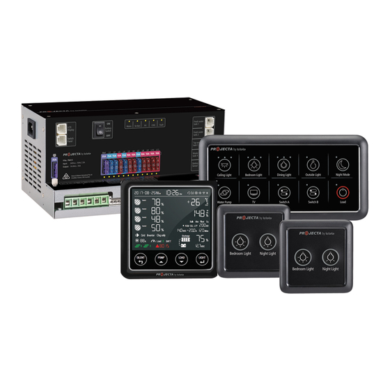
Projecta INTELLI-RV PM400 Instruction Manual
12v power management system
Hide thumbs
1
2
Table Of Contents
3
4
5
6
7
8
9
10
11
12
13
14
15
16
17
18
19
20
21
22
23
24
page
of
24
Go
/
24
Contents
Table of Contents
Troubleshooting
Bookmarks
Table of Contents
Table of Contents
1 Introduction
Features
Monitor
Position Switch Panel
Bedroom Switch Panel
Water Tank Probe
2 Key Features and Functions
Multiple Inputs
Battery Charger of Stationery/Service Battery
Vehicle Battery Charger
Power Supply Mode
MPPT Solar Charger Controller
Voltage Charging Relay (VCR)
Categorised Outputs
Battery Low Voltage Protection
Manual Battery Switch
Precise Battery Measurement
Silent Mode
3 Structure and Installation
PM435 Power Management System
Monitor
And 2 Position Switch Panel
Water Tank Probe
PMWS400 Water Tank Probe
PMWS200 Water Tank Probe
4 Wiring
Material
System Schematic
Preparation
Connection
5 Display
PM435 Master Power Unit
Position Switch Panel PM4SW10
Position Switch Panel PM4SW2
Monitor PMLCD-BT
Monitor Symbol Explanation
Switch Explanation
Alphabet Explanation
6 Operation
Configuration on PM435
Battery Capacity and Battery Type
Select Battery Switch Local/Remote
Configuration on Monitor
Monitor Configuration Menu
Operation of Switch Panels PM4SW10 and PM4SW2
Maintenance
Battery Monitor Maintenance
7 Trouble Shooting
Display on PM435 Unit
Error Code on Monitor
8 Specification
Advertisement
Quick Links
1
Features
2
Monitor
3
Monitor Pmlcd-Bt
4
Error Code on Monitor
Download this manual
INTELLI-RV
12V POWER MANAGEMENT SYSTEM
(Not inc. PM435-BT)
(Not inc. PM435-BT)
P/No. PM400 & PM435-BT
Table of
Contents
Previous
Page
Next
Page
1
2
3
4
5
Advertisement
Table of Contents
Need help?
Do you have a question about the INTELLI-RV PM400 and is the answer not in the manual?
Ask a question
Questions and answers
Related Manuals for Projecta INTELLI-RV PM400
Battery Charger Projecta INTELLI-RV Instruction Manual
(24 pages)
Control Unit Projecta INTELLI-RV Installation Manual
500amp shunt module (9 pages)
Motorhomes Projecta INTELLI-RV PM435-BT Instruction Manual
12v power management system (24 pages)
This manual is also suitable for:
Intelli-rv pm435-bt
Pm4sw10
Pm4sw2
Pmlcd-bt
Intelli-rv
Pm400
...
Show all
Pm435-bt
Table of Contents
Save PDF
Print
Rename the bookmark
Delete bookmark?
Delete from my manuals?
Login
Sign In
OR
Sign in with Facebook
Sign in with Google
Upload manual
Upload from disk
Upload from URL


Need help?
Do you have a question about the INTELLI-RV PM400 and is the answer not in the manual?
Questions and answers